Download presentation
Presentation is loading. Please wait.

1
GENERATOR PROTECTION

2
Generator Differential Protection (87 G)
It is unit type protection, covering the stator winding for phase to phase faults due to breakdown of insulation between stator phase windings. This relay is not sensitive for single line to earth faults as the earth fault current is limited due to the high neutral earthing resistance. If CTs of identical ratios are used on neutral and line side of generator, an operating current setting of 20% it can be adopted. It is instantaneous in operation and it trips the generator breaker (Class – A) to eliminate the system in – feed to the fault along with field breaker and turbines. For all machines of ratings 10 MVA and above, this protection shall be provided.
 to eliminate the system in – feed to the fault along with field breaker and turbines. For all machines of ratings 10 MVA and above, this protection shall be provided.")
4
Backup impedance Protection (21G)
This operates for phase faults in the unit, in the HV yard or in the adjacent transmission lines, with a suitable time delay. It operates as a backup when the corresponding main protection fails. In A.P. System the reach is set as 120% of generator transformer with a time delay of about 1.0 to 1.5 Sec.

5
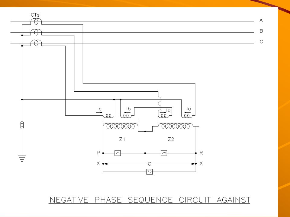
Negative phase sequence protection (46 G
It safeguards the generator rotor against over heating caused by the induced double frequency (100 Hz) currents when negative phase sequence currents are present in the stator. The negative phase sequence current(I2) can appear due to unbalanced single phase loads or transmission line unsymmetrical faults.
 currents when negative phase sequence currents are present in the stator. The negative phase sequence current(I2) can appear due to unbalanced single phase loads or transmission line unsymmetrical faults.")
6
It should be set according the Negative Phase Sequence capability of the generator.
I2 **2 x t = for Thermal Units = for Hydro Units Alarm stage can be set at 50% of continuous withstand capability of the machine with a time delay of 3 to 5 Sec.

8
Voltage restrained overcurrent protection (51 / 27 G)
This will operate when the fault current from the generator terminals becomes low with under voltage criteria. It operates as a backup protection for system faults with suitable time delay.

9
Generator Stator Earth Fault Protection (64G):-
The high neutral earthing resistance arrangement limits the generator earth fault current, minimising the damage to core laminations. Although a single phase earth fault is not critical, it requires clearance within a short time due to: It may develop into a phase to phase fault If a second earth fault occurs the current is not longer limited by the earthing resistor. Fire may result from earth fault arc.

11
100% stator protection is impossible with resistor earthing
It depends on value of resistor& relay setting 100% FULL LOAD resistor&20% relay setting gives 80% winding protection Dist . Tr 15.75kv/240v ohms

12
95% stator earth fault protection (64G1):-
It is an over voltage relay monitoring the voltage developed across the secondary of the neutral grounding transformer in case of ground faults. It covers generator, LV winding of generator transformer and HV winding of UAT. A pickup voltage setting of 5% is adopted with a time delay setting of about 1.0 Sec. For all machines of ratings 10 MVA and above this shall be provided.

13
100% stator earth fault protection (64G2)
This is a 3rd harmonic U/V relay. It protects 100% of stator winding. During the machine running condition there will be certain third harmonic voltage at neutral side of the generator.This 3rd harmonic voltage will come down when a stator earth fault occurs causing this relay to operate. This shall have voltage check or current check unit, to prevent faulty operation of the relay at generator stand still or during the machine running down period.

14
Loss of Excitation (40G):-
In case of loss of excitation, the generator goes out of synchronism and starts running asynchronously at a speed higher than the system, absorbing reactive power from the system. Under these conditions, the stator end regions and part of the rotor get over heated. This protection shall have: Mho characteristic lying in 3rd and 4th quadrants of impedance diagram with adjustable reach and offset. An under voltage and / or overcurrent relay as additional check. A timer with adjustable range of 1-10 Sseconds. Recommended Settings:- - Diameter of Mho circle =Xd(synchronous reactance) - Off set of Mho circuit from the origin = xd1/2(trans.reactance) - Time delay = 1 Sec. - Under voltage relay
 - Off set of Mho circuit from the origin = xd1/2(trans.reactance) - Time delay = 1 Sec. - Under voltage relay.")
15
Low Forward Power Relay (37G):-
In thermal machines, when the steam flow through turbine is interrupted by closing the the governor valves, the remaining steam in the turbine generates (low) power and the machine enters to motoring conditions drawing power from the system. This protection detects low forward power conditions of the generator and trips generator breaker after a time delay, avoiding motoring of generator. The low forward power relay will be provided with ‘turbine trip’ interlock in thermal machines. A setting of 0.5% of rated active power of generator with a time delay of 2.0 Sec. shall be adopted.
 power and the machine enters to motoring conditions drawing power from the system. This protection detects low forward power conditions of the generator and trips generator breaker after a time delay, avoiding motoring of generator. The low forward power relay will be provided with ‘turbine trip’ interlock in thermal machines. A setting of 0.5% of rated active power of generator with a time delay of 2.0 Sec. shall be adopted.")
16
Reverse Power relay (32G Reverse power protection shall be used for all types of generators. When the input to the turbine is interrupted the machine enters into motoring condition drawing power from the system. Reverse power relay protects the generators from motoring condition. In thermal machines, reverse power condition appears subsequent to low forward power condition. For reverse power relay, a setting of 0.5% of rated active power of generator with 2 stage timer as given below. Stage – I: - With turbine trip interlock, a time delay of 2 Sec. shall be adopted. ii) Stage – II:- Without ‘ turbine trip’ interlock, a time delay of about 20 Sec. can be adopted to avoid unnecessary tripping of unit during system disturbance causing sudden rise in frequency or power swing conditions.
 Stage – II:- Without ‘ turbine trip’ interlock, a time delay of about. 20 Sec. can be adopted to avoid unnecessary tripping of unit during system disturbance causing sudden rise in frequency or power swing conditions.")
17
Rotor earth fault protection

18
This protection shall be provided for machines of all sizes
This protection shall be provided for machines of all sizes. This protection shall be connected for alarm and the operator may take the machine at the earliest opportunity after the first earth fault has occurred. This protection will have a sensitive voltage function operating on bridge measurement basis with auxiliary equipment. It will have two levels, one for alarm and one for trip. The settings adopted in general are: i) For alarm : 25 KJ Ohm, 1.0 Sec. ii) For trip : 5 K Ohm, 0.5 Sec.
 For alarm : 25 KJ Ohm, 1.0 Sec. ii) For trip : 5 K Ohm, 0.5 Sec.")
19
Generator Under Frequency Protection (81 G):
The Under Frequency Protection: - Prevents the steam turbine and generator from exceeding the permissible operating time at reduced frequencies. - Ensures that the generating unit is separated from the network at a preset value of frequency. - Prevent overfluxing (v/f) of the generator (large overfluxing for short times). The stator under frequency relay measures the frequency of the stator terminal voltage. Setting Recommendations:- For Alarm : 48.0 Hz, 2.0 Sec. time delay. For Trip : 47.5 Hz, 1.0 Sec. (or) As recommended by Generator Manufacturers.
 of the generator (large overfluxing for short times). The stator under frequency relay measures the frequency of the stator terminal voltage. Setting Recommendations:- For Alarm : 48.0 Hz, 2.0 Sec. time delay. For Trip : 47.5 Hz, 1.0 Sec. (or) As recommended by Generator Manufacturers.")
20
Generator Over voltage Protection (59 G):
An over voltage on the terminals of the generator can damage the insulator of the generator, bus ducting, breakers, generator transformer and auxiliary equipment. Hence over voltage protection should be provided for machines of all sizes. Settings recommendations:- Stage-I : Over voltage pickup = 1.15 x Un Time delay = 10 Sec. State-II : Over voltage pickup = 1.3 x Un Time delay = 0.5 Sec.

21
THANK YOU

Similar presentations


>")


