Download presentation
Presentation is loading. Please wait.

2
Mechanical Ventilator/Patient Monitoring Part II RET 2264C Prof. J.M. Newberry Dr. J.B. Elsberry Special Thanks to Sean Chambers, J. Cairo and Jeff Davis

3
Physiological Monitoring Physiological data are useful in managing patients on ventilatory support in respect to oxygenation, ventilation, ventilatory mechanics (Use Loops), and hemodynamic monitoring…
, and hemodynamic monitoring…")
4
Hemodynamics Physics of Blood flow in the circulation

5
Circulatory System

6
Circulation Schematic Lungs Tissues Left Side of Heart Right Side of Heart AV VA Pulmonary Vein Pulmonary Artery Aorta Sup. & Inf. Vena Cava Mitral Valve Pulmonary Valve Aortic Valve Tricuspid Valve

7
Heart Valves Atrioventricular (A-V) valves - separate Atria from Ventricles Bicuspid (Mitral) - Left Side Tricuspid - Right Side Semi-Lunar Valves - separate ventricles from Arteries
 valves - separate Atria from Ventricles Bicuspid (Mitral) - Left Side Tricuspid - Right Side Semi-Lunar Valves - separate ventricles from Arteries")
8
Opening, Closing of Valves - Depends on Pressure differences between blood in adjacent areas

9
Heart Sounds ‘Lubb’ (1 st sound) - Closure of A-V valves ‘Dupp’ (2 nd sound) - Closure of S-L valves Caused by Turbulence on closing. Anything extra ’Murmur’ (swishing of blood) Could be due to: Stenosis of Valves (calcification) Valves not closing properly (Incompetence, Insufficiency) Increases Pressure on heart
 Could be due to: Stenosis of Valves (calcification) Valves not closing properly (Incompetence, Insufficiency) Increases Pressure on heart.")
10
Blood Vessels Arteries Capillaries Veins Systemic Pathway: Left Ventricle Aorta Arteries Arterioles of Heart Capillaries VenulesVeins Right Atrium of Heart

11
Blood Composition: –Approx 45% by Vol. Solid Components »Red Blood Cells (12 m x 2 m) »White Cells »Platelets –Approx 55% Liquid (plasma) »91.5% of which is water »7% plasma proteins »1.5% other solutes
 »White Cells »Platelets –Approx 55% Liquid (plasma) »91.5% of which is water »7% plasma proteins »1.5% other solutes.")
12
Blood Functions Transportation of blood gases, nutrients, wastes Homeostasis (regulation) of pH, Body Temp, water content Protection
 of pH, Body Temp, water content Protection")
13
Viscosity of Blood = 3 3.5 times of water Blood acts as a non-newtonian fluid in smaller vessels (including capillaries)
")
14
Cardiac Output Flow of blood is usually measured in l/min Total amount of blood flowing through the circulation = Cardiac Output (CO) Cardiac Ouput = Stroke Vol. x Heart Rate or SV 1 + SV 2 + …+ SV n = C.O. l/min Influenced by Blood Pressure & Resistance Force of blood against vessel wall Blood viscosity Vessel Length Vessel Elasticity Vasconstriction / Vasodilation with water retention with dehydration, hemorrage

15
Overall Greater Pressure Greater Blood DifferencesFlow Greater Resistance Lesser Blood Flow

16
CARDIOVASCULAR SYSTEM HEART (PUMP) VESSELS (DISTRIBUTION SYSTEM) REGULATION AUTOREGULATION NEURAL HORMONAL RENAL-BODY FLUID CONTROL SYSTEM
 VESSELS (DISTRIBUTION SYSTEM) REGULATION AUTOREGULATION NEURAL HORMONAL RENAL-BODY FLUID CONTROL SYSTEM")
17
Driving force for blood flow is pressure created by ventricular contraction Elastic arterial walls expand and recoil continuous blood flow ¶ Blood Pressure

18
VEINS CAPACITY VESSELS HEART 80 mmHg 120 mmHg SYSTOLE DIASTOLE ARTERIES (LOW COMPLIANCE) CAPILLARIES
 CAPILLARIES")
19
Blood pressureBlood pressure is highest in the arteries (Aorta!) and falls continuously... Blood pressure Systolic pressure in Aorta: 120 mm Hg Diastolic pressure in Aorta: 80 mm Hg Diastolic pressure in ventricle: ?? mm Hg

20
Ventricular pressure difficult to measure arterial blood pressure assumed to indicate driving pressure for blood flow Arterial pressure is pulsatile useful to have single value for driving pressure: Mean Arterial Pressure MAP = diastolic P + 1/3 pulse pressure

21
Pulse Pressure = systolic pressure - ?? = measure of amplitude of blood pressure wave

22
MAPMAP influenced by MAP Cardiac output Peripheral resistance MAP CO x R arterioles Blood volume –fairly constant due to homeostatic mechanisms (kidneys!!)
")
23
BP too low: Driving force for blood flow unable to overcome gravity O 2 supply to brain Symptoms?

24
BP too high: Weakening of arterial walls - AneurysmWeakening of arterial walls - Aneurysm Risk of rupture & hemorrhage Cerebral hemorrhage: ? Rupture of major artery:

25
Principles of Estimated Sphygmomanometry what kind of sound? Cuff inflated until brachial artery compressed and blood flow stopped what kind of sound?

26
turbulent flow Slowly release pressure in cuff:

27
Pressure at which...... sound (= blood flow) first heard:... sound disappeared:
 first heard:... sound disappeared:")
28
Pressure can be stated in terms of column of fluid. Pressure Units mm Hgcm H 2 OPSI ATM 50 680.9 0.065 100 1361.9 0.13 200 2723.8 0.26 300 4085.7 0.39 400 5447.6 0.52

29
Pressure = Height x Density orP = gh If Right Atrial pressure = 1 cm H 2 O in an open column of blood Pressure in feet = 140 cm H 2 O Rupture Venous Valves Density of blood = 1.035 that of water Incompetent venous valves Varicosities Actual Pressure in foot = 4-5 cm H 2 O

30
Pressures in the Circulation Review Pressures in the arteries, veins and heart chambers are the result of the pumping action of the heart The right and left ventricles have similar waveforms but different pressures The right and left atria also have similar waveforms with pressures that are similar but not identical

31
How do we Continuously Monitor Left and Right Heart Pressures

32
Hemodynamic Function Summarized in these Wiggers Diagrams from Pilbeam-Cairo

33
1. The LV pressure begins to rise after the QRS wave of the ECG 2. Pressure rises until the LV pressure exceeds the aortic pressure The blood begins to move from the ventricle to the aorta 3. As blood enters the aorta, the aortic pressure begins to rise to form the systolic pulse 4. As the LV pressure falls in late systole the aortic pressure falls until the LV pressure is below the aortic diastolic press. 5. Then the aortic valve closes and LV pressure falls to LA pressure

34
The first wave of atrial pressure (the A wave) is due to atrial contraction The second wave of atrial pressure (the V wave) is due to ventricular contraction
 is due to atrial contraction The second wave of atrial pressure (the V wave) is due to ventricular contraction")
35
Normal Pressures RV and pulmonary systolic pressures are 15-25 mm Hg Pulmonary diastolic pressure is 5-12 mm Hg LA pressure is difficult to measure because access to the LA is not direct

36
The severity of AS is determined by the pressure drop across the aortic valve or by the aortic valve area The high velocity of blood flow through the narrowed valve causes turbulence and a characteristic murmur AS can be diagnosed with a stethoscope AS produces a pressure gradient between the aorta and LV i.e. For blood to move rapidly through a narrowed aortic valve orifice, the pressure must be higher in the ventricle

37
Pressure Measurement Accurate pressure measurements are essential to understanding the status of the circulation In 1733 Steven Hales connected a long glass tube directly to the left femoral artery of a horse and measured the height of a column of blood (8 feet, 3 inches) to determine mean BP Direct pressure measurements are made frequently in the cardiac catheterization laboratory, the ICU and the OR
 to determine mean BP Direct pressure measurements are made frequently in the cardiac catheterization laboratory, the ICU and the OR")
38
A tube is inserted into an artery and connected to an electrical strain gauge that converts pressure into force that is sensed electrically The output of the transducer is an electrical signal that is amplified and recorded on a strip chart For correct pressure measurements the cannula and transducer must be free of air, the cannula should be stiff and short

39
Cardiac Output (CO)Measurement The measurement of blood flow through the circulation is usually done clinically using either the Fick method or Thermodilution The Fick method states that the cardiac output is equal to the oxygen consumption divided by the arterial-venous oxygen difference CO = Oxygen consumption / A-V O 2
Measurement The measurement of blood flow through the circulation is usually done clinically using either the Fick method or Thermodilution The Fick method states that the cardiac output is equal to the oxygen consumption divided by the arterial-venous oxygen difference CO = Oxygen consumption / A-V O 2")
40
MEASUREMENT OF CARDIAC OUTPUT THE FICK METHOD: VO 2 = ([O 2 ] a - [O 2 ] v ) x Flow Flow = VO 2 [O 2 ] a - [O 2 ] v Spirometry or nomogram (250 ml/min ) Arterial Blood (20 ml%) Pulmonary Artery Blood (15 ml%) CARDIAC OUTPUT PERIPHERAL BLOOD FLOW VENOUS RETURN PULMONARY BLOOD FLOW
![MEASUREMENT OF CARDIAC OUTPUT THE FICK METHOD: VO 2 = ([O 2 ] a - [O 2 ] v ) x Flow Flow = VO 2 [O 2 ] a - [O 2 ] v Spirometry or nomogram (250 ml/min ) Arterial Blood (20 ml%) Pulmonary Artery Blood (15 ml%) CARDIAC OUTPUT PERIPHERAL BLOOD FLOW VENOUS RETURN PULMONARY BLOOD FLOW](http://images.slideplayer.com/35/10284641/slides/slide_40.jpg "MEASUREMENT OF CARDIAC OUTPUT THE FICK METHOD: VO 2 = ([O 2 ] a - [O 2 ] v ) x Flow Flow = VO 2 [O 2 ] a - [O 2 ] v Spirometry or nomogram (250 ml/min ) Arterial Blood (20 ml%) Pulmonary Artery Blood (15 ml%) CARDIAC OUTPUT PERIPHERAL BLOOD FLOW VENOUS RETURN PULMONARY BLOOD FLOW")
41
CARDIAC OUTPUT (Q) = VO 2 [O 2 ] a - [O 2 ] v 250 ml/min 20 ml% - 15 ml% = = 5 L/min. Q = HR x SV. SV = Q HR. = 5 L/min 70 beats/min = 0.0714 L or 71.4 ml CARDIAC INDEX = Q m 2 body surface area. 5 L/min 1.6 m 2 = = 3.1 L/min/m 2
![CARDIAC OUTPUT (Q) = VO 2 [O 2 ] a - [O 2 ] v 250 ml/min 20 ml% - 15 ml% = = 5 L/min.](http://images.slideplayer.com/35/10284641/slides/slide_41.jpg "Q = HR x SV. SV = Q HR. = 5 L/min 70 beats/min = L or 71.4 ml CARDIAC INDEX = Q m 2 body surface area. 5 L/min 1.6 m 2 = = 3.1 L/min/m 2.")
42
Oxygen Delivery to the Tissues It’s simple but very important DO 2 = CaO 2 x Qc.

43
The measurement is done by determining the oxygen consumption using respiratory gas measurements and the O 2 content of arterial and mixed venous blood The mixed venous blood sample is obtained from a PA with a catheter The arterial sample can be drawn from any artery

44
Indications & Contraindications for Arterial Cannulation Arterial Cannulation Continuous BP, frequent ABG’s Complications—hemorrhage, infection, ischemia (embolus, thrombus, arterial spasm)
")
45
Indications & Contraindications for Venous Cannulation Central Venous Catheter: Fluid admin., nutritional support, CVP measurements/monitoring Complications: pneumothorax, embolus & thrombus formation, infection Pulmonary Artery Catheter: PCWP measurements, Cardiac Output and mixed venous blood gases Complications: pneumothorax, arrhythmias, embolus & thrombus formation, infection and cardiovascular injury

46
Hemodynamic Pressures that Can be Measured Directly Heart Rate: 60-90/min Systemic (Arterial) BP: 90-140/60-90 torr CVP 2-6 torr PAP: 15-35/5-15 torr PCWP: 5-12 torr C.O. (Q): 4-8 l/min. PvO 2 : 40 torr PaO 2 : 80-100 torr. - -
: 4-8 l/min. PvO 2 : 40 torr PaO 2 : torr")
47
Next PA Monitoring Supine O to 60 degrees from horizontal Angles 45° 30° 0°

49
Components of Hemodynamic Pressure Monitoring The invasive catheter and the high pressure tubing connecting the patient to the transducer The transducer The flush system The bedside monitor

51
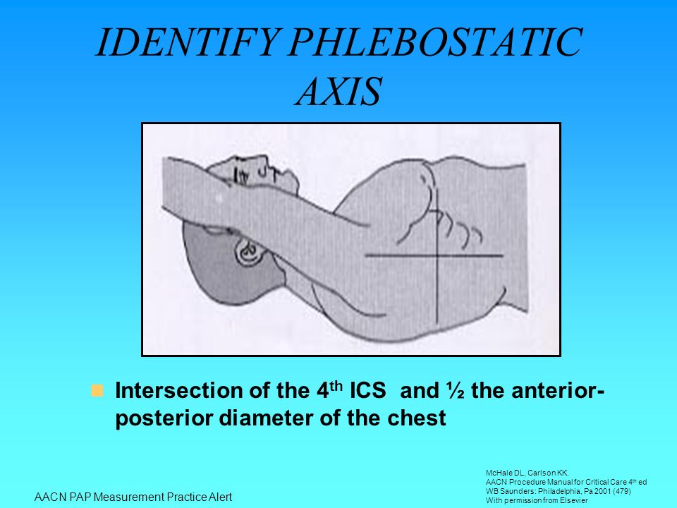
Intersection of the 4 th ICS and ½ the anterior- posterior diameter of the chest IDENTIFY PHLEBOSTATIC AXIS AACN PAP Measurement Practice Alert McHale DL, Carlson KK. AACN Procedure Manual for Critical Care 4 th ed WB Saunders: Philadelphia, Pa 2001 (479) With permission from Elsevier
 With permission from Elsevier.")
52
LEVELING –Eliminates effects of hydrostatic forces on the observed hemodynamic pressures –Ensure air-fluid interface of the transducer is leveled before zeroing and/or obtaining pressure readings –Phlebostatic axis: Level of left atrium 4 th ICS & ½ AP diameter Mark the chest with washable felt pen AACN PAP Measurement Practice Alert

53
UNDER DAMPED SYSTEM

54
OVER DAMPED SYSTEM –Sluggish, artificially rounded & blunted appearance –SBP erroneously low; DBP erroneously high –Causes: large air bubbles in system, ostial lesion, compliant tubing, loose/open connections, low fluid level in flush bag AACN PAP Measurement Practice Alert Reprinted from Darovic GO. Hemodynamic Monitoring: Invasive and Noninvasive Clinical Application 2 nd ed. Philadelphia,Pa: WB Saunders Co;1995;161-162 Used with permission from Elsevier

55
AO Pressure

56
Damped AO Pressure

57
PAP DOCUMENTATION Measure at end expiration Measure pressures from a graphic tracing Measure pulmonary capillary wedge pressure at end-expiration using the mean of the a wave –a wave indicates atrial contraction and falls within the P – QRS interval of the corresponding ECG complex Measure at end expiration Measure pressures from a graphic tracing Measure pulmonary capillary wedge pressure at end-expiration using the mean of the a wave –a wave indicates atrial contraction and falls within the P – QRS interval of the corresponding ECG complex AACN PAP Measurement Practice Alert

58
RESPIRATORY COMPONENT Changes in intrathoracic pressure during respiration change PAP readings Record and trend pressure readings at end expiration AACN PAP Measurement Practice Alert

59
Used with permission of PACEP Collaborative

60
AACN PAP Measurement Practice Alert

61
Accurate Measurement Regular zero check Open transducer to room air Hit balance button on monitor Zero in Ft. Myers does not = zero in Denver

62
Effect of air in line

63
Effect of long line

64
Troubleshooting What can we do to reduce damping thus ensuring the best frequency response? –Short, stiff tubing –No blood, contrast or air in line

65
Correctable Sources of Artifact Review Loss of frequency response –Air, blood, contrast Improper zero –Phlebostatic axis Improper calibration –Hg if valve case

Similar presentations


![Circulatory System. Figure 24.01 Transports materials throughout body: Nutrients Metabolic wastes Gases (O 2 & CO 2 ) Hormones [regulate body processes]](/14/4284594/big_thumb.jpg "Circulatory System. Figure 24.01 Transports materials throughout body: Nutrients Metabolic wastes Gases (O 2 & CO 2 ) Hormones [regulate body processes]>")


 Transport O 2, nutrients, hormones, cell wastes, etc…>")


