Download presentation
Presentation is loading. Please wait.

1
Site Investigation William J. Likos, Ph.D. Department of Civil and Environmental Engineering University of Wisconsin-Madison GLE/CEE 330 Lecture Notes Soil Mechanics

2
A. Purposes for Site Investigation: 1.Site Characterization (geometry) –Define type and extent of soil and rock –Define location of groundwater –Define stress history of site –Identify potential problem conditions (e.g. karst, contaminants)
 –Define type and extent of soil and rock –Define location of groundwater –Define stress history of site –Identify potential problem conditions (e.g. karst, contaminants).")
3
Purposes for Site Investigation con’t 2.Obtain samples for testing –Index and characterization tests u moisture content u Atterberg limits u grain size distribution –Strength tests for stability problems u unconfined compression u direct shear u triaxial –Deformation tests for settlement u consolidation tests –Other tests u hydraulic conductivity u compaction u contamination

4
B. General Considerations: l Structure –more critical and complex => more extensive investigation l Site –More complex site => more extensive investigation l Familiarity with site geology –More familiarity => less extensive investigation l Economics –How much benefit will one more boring provide? –Drilling/sampling ~ $2k-$5k per day (depending) l Client –Can influence extent of investigation, but not too much! l Codes
 l Client –Can influence extent of investigation, but not too much. l Codes.")
5
C. Preliminary Investigation: l Plans for site development –Site plan with finished grades and structure location(s) –Approximate magnitudes of loads –Sensitivity of structure to settlements l General site conditions –Company reports/files –Geologic maps –Topographic maps –USCS soil surveys (surficial soils) –Air/Satellite Images (Google Earth) –Newspaper articles
 –Approximate magnitudes of loads –Sensitivity of structure to settlements l General site conditions –Company reports/files –Geologic maps –Topographic maps –USCS soil surveys (surficial soils) –Air/Satellite Images (Google Earth) –Newspaper articles.")
6
Geologic Maps

7
Topographic Maps

8
Aerial Photographs See http://terraserver.microsoft.com/

9
D. Site Visit – Items to take: l Info from preliminary investigation (e.g. reports, topo’s, geo’s, aerial photos, etc.) l Note pad, notebook, or site inspection form (take notes on everything!! – time, weather…) l Camera l Small shovel or hand auger l Compass l Tape l Level
 l Note pad, notebook, or site inspection form (take notes on everything!. – time, weather…) l Camera l Small shovel or hand auger l Compass l Tape l Level.")
10
Site Visit – items to look for: 1.Site address/location 2.Date and time 3.Current and recent weather conditions 4.Site accessibility (e.g. terrain, right of way, gates, etc.) 5.Power lines 6.Availability of water and electricity 7.Ground slopes and any evidence of movement 8.Locations of trees, brush, streams, marshes 9.Rock outcrops (note type and condition) 10.Evidence of prior filling 11.Existing or prior structures 12.Evidence of contamination 13.Manholes, utilities, etc. 14.Others…
 5.Power lines 6.Availability of water and electricity 7.Ground slopes and any evidence of movement 8.Locations of trees, brush, streams, marshes 9.Rock outcrops (note type and condition) 10.Evidence of prior filling 11.Existing or prior structures 12.Evidence of contamination 13.Manholes, utilities, etc. 14.Others….")
11
E. Methods of Subsurface Exploration l Test Pits l Hand Auger l Truck-mounted Power Auger l Wash Boring l Rotary Wash Boring l Rock Coring l Cone-penetration Test l Other in-situ tests

12
E.1 Test Pits l Excavated by hand or backhoe l Generally < 20-ft deep l Uses –Locate active faults –Locate thin seams –Investigate potential borrow areas

13
Excavations and Road Cuts

14
E.1 Test Pits l Advantages –Can view soil directly (helps locate small but critical seams) –Can obtain large quantities of disturbed soil for testing –Can hand carve undisturbed samples –Can perform field tests (e.g. plate load tests) l Disadvantages –Economically limited to 10-ft to 20-ft depth –Dewatering required below water table –Numerous test pits disrupt site –Cost of excavation in rock may be prohibitive
 l Disadvantages –Economically limited to 10-ft to 20-ft depth –Dewatering required below water table –Numerous test pits disrupt site –Cost of excavation in rock may be prohibitive.")
15
E.2 Hand Augers l 2-in to 6-in diameter l Can drill to perhaps 25-ft l Used where access is restricted or mobilization costs for motorized rigs are prohibitive

16
E.2 Hand Augers l Advantages –Low cost –Portability –Requires minimal headroom l Disadvantages –Maximum depth restricted –Cannot obtain high quality “undisturbed” samples –Cannot bore through rock, hard clay, or sand below water table –Slow and labor intensive

17
E.3 Truck-mounted Power Auger l 4-in to 12-in continuous flight augers l Can drill to depths of 150-ft.

18
Hollow and Solid-stem Augers

19
E.4 Wash Boring l Tripod Rig with “cathead” l Hole advanced by chopping/cutting head and fluid flow to return cuttings

20
E.4 Wash Boring l Advantages –Low equipment costs –Adaptable to any terrain –Can drive sampler at bottom of hole l Disadvantages –Depth of drilling limited by weight of drilling rods (generally <50-ft. –Slow drilling through hard clays and gravel –Labor intensive –Difficult to get location of GWT –Cannot push samplers –Set up time is several hours

21
E.5 Rotary Wash Boring l Same principle as wash boring but with added motorized rotary action l Often combined with power auger

22
E.5 Rotary Wash Boring l Advantages –Relatively rapid drilling through almost any soil –Maximum depth from several hundred to several thousand feet –“Undisturbed” samples can be obtained by pushing or driving samples –Can drill in soft clay or sand is drilling mud (slurry) is used l Disadvantages –Drilling rigs are relatively expensive –Difficult to accurately measure GWT is slurry used –Set-up/clean-up time may be several hours per hole –Rig accessibility is primary concern –Drilling mud must be disposed – environmental concern –Difficult to retain drilling mud in highly permeable strata
 is used l Disadvantages –Drilling rigs are relatively expensive –Difficult to accurately measure GWT is slurry used –Set-up/clean-up time may be several hours per hole –Rig accessibility is primary concern –Drilling mud must be disposed – environmental concern –Difficult to retain drilling mud in highly permeable strata")
23
Rig Types

24
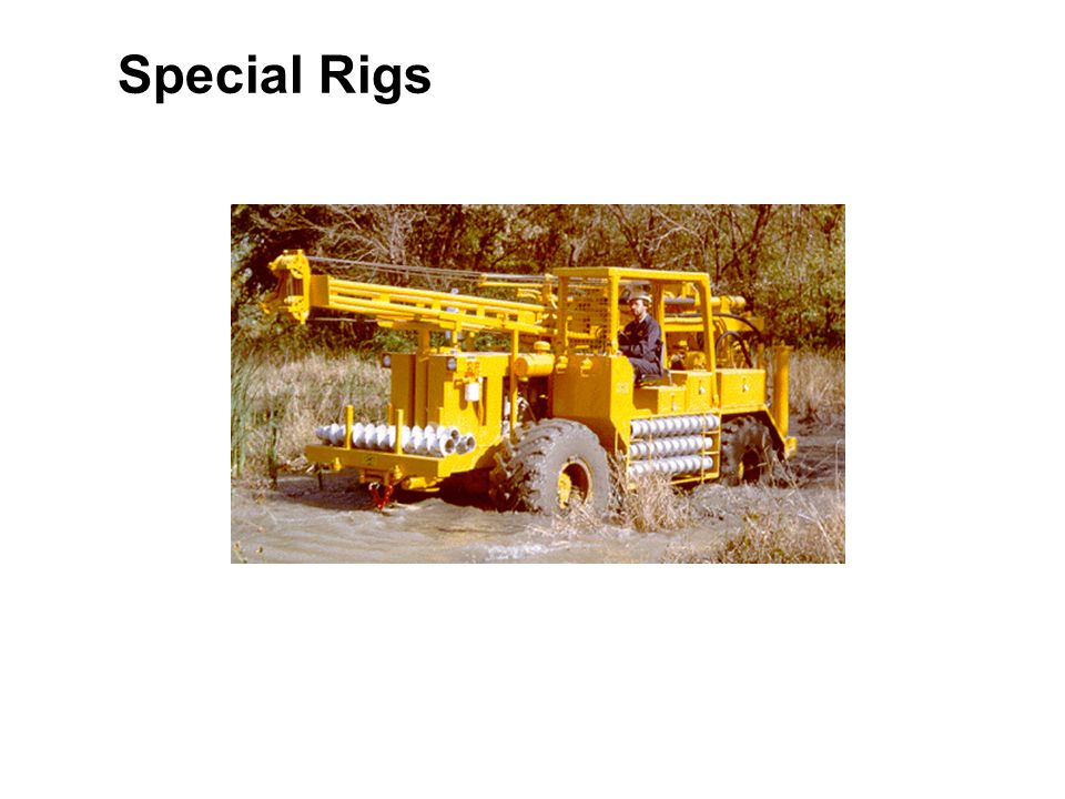
Special Rigs

26
Safety First

27
Sampling

28
l Important Engineering Properties –Shear Strength –Compressibility –Permeability l Causes of disturbance 1.Remolding of soil - Friction/smearing along side walls - “Squeezing” soil into sampler 2.Unloading of soil - May cause change in soil structure

29
Sampler Characteristics - As A R increases, sample quality decreases - For high quality samples, A R <=15% Area Ratio Inside Clearance Ratio - Typical values - Need some friction to hold sample

30
Sample Recovery Ratio Ideally, R R = 1 but may be 1

31
Standard Sampler (a.k.a. split spoon) l Primarily used for Standard Penetration Test (SPT) l Can be used to sample in difficult soils l Samples obtained are badly disturbed l A R is 110%
 l Primarily used for Standard Penetration Test (SPT) l Can be used to sample in difficult soils l Samples obtained are badly disturbed l A R is 110%.")
32
Standard Sampler

33
Shelby Tube Sampler l Commonly 2-inch to 3-inch O.D. (up to 5-inch) l Wall thickness of 0.06-inch to 0.15-inch l AR is 10 to 15 % for 3-inch tubes l Lengths vary from 24 to 36 inches
 l Wall thickness of 0.06-inch to 0.15-inch l AR is 10 to 15 % for 3-inch tubes l Lengths vary from 24 to 36 inches.")
34
Lined Samplers l Generally rugged, thick- walled samplers with large A R l Intent is to minimize disturbance due to unloading l Liner can be made convenient size for: –Consol. Tests –Permeability tests –Direct shear tests –Triaxial tests

35
Core Barrels l Use for drilling and sampling in rock l Come in several common sizes (e.g. RX) l Use hollow diamond bit to drill through rock l Can use stationary inner barrel within outer rotating barrel to protect rock core l Use recovery ratio and other rock core characteristics to establish suitability of rock (don’t want to break due to coring!) l Can test intact pieces of rock in lab
 l Use hollow diamond bit to drill through rock l Can use stationary inner barrel within outer rotating barrel to protect rock core l Use recovery ratio and other rock core characteristics to establish suitability of rock (don’t want to break due to coring!) l Can test intact pieces of rock in lab.")
36
Distribution of Disturbance

37
Effects of Disturbance l Sands: –Loose sands generally become more dense (unsafe!) –Dense sands generally become more loose (conservative) l Clays: Specimen Source Avg. Undrained Strength 1.9” Shelby1333 psf 3.4” Shelby1990 psf 3.4” Shelby – trimmed to 1.5” 2120 psf Strength Compressibility

38
In-situ Testing l Standard Penetration Test (SPT) l Cone Penetration Test (CPT) l Others: –Vane Shear Test –Pressuremeter (PMT) –Flat Plate Dilatometer (DMT) –Geophysical Tests
 l Cone Penetration Test (CPT) l Others: –Vane Shear Test –Pressuremeter (PMT) –Flat Plate Dilatometer (DMT) –Geophysical Tests")
39
Standard Penetration Test l Most common in-situ test l SPT “N-value” is number of blows of special hammer required to penetrate standard sampler 12 inches l Procedure: –140-lb hammer –30-inch drop –Penetrate total distance of 18-inches, measure the number of blows required for each 6-inch increment –Compute “N-value” by summing number of blows for last 12-inches of penetration

40
Common SPT Hammers

41
Cone Penetration Test

42
Cone Penetration Rig

43
Cone Penetration Log

44
Other In-situ Tests

45
Geophysical Tests

Similar presentations


>")


