Download presentation
Presentation is loading. Please wait.

1
Orthographic Projection Welcome Engineering Graphics - Lect

2
Types of lines Line for an outline of view Projection line Hidden line Center line

3
Applications of Types of Lines

4
4 Objects are not always drawn to their actual size. They may be too large to fit a standard drawing sheet, or too small for all details to clearly show. For example, a microchip circuit must be drawn at several thousand times its actual size to be seen. On the other side, a plan view of a small town must be drawn with reduced scale than the actual size. Drawing Scale

5
5 Type of scaleRecommended scale Reduction scale 1:101:21:5 1:1001:201:50 1:10001:2001:500 1:100001:20001:5000 Enlargement scale 10:120:150:1 2:15:1 Full scale1:1 Drawing Scale

6
Projection Projection : In Engineering drawing, the word projection means an image or the act of obtaining the image of an object. Technical people often refer to the image as a view.

8
Projection Methods Orthographic Projection Isometric Projection Oblique Projection Perspective Projection

9
Orthographic Projection Multiview Drawings

10
Technique used to present a three- dimensional object (an object having height, width and depth) As a group of related two-dimensional views ( having only width and height, or width and depth). 10 Multiview drawing

11
A better way to fully describe the bus graphically would be to create a multiview drawing. The multiview drawing of the bus is represented by six views, the front, top, sides, back and bottom. These views represent the six “regular” views of the bus. Top View Front View Bottom View Right View Left View Back View 11

12
The 6 principle views are created by looking at the object, straight on, in the directions indicated. 12 The Six Principle Views

13
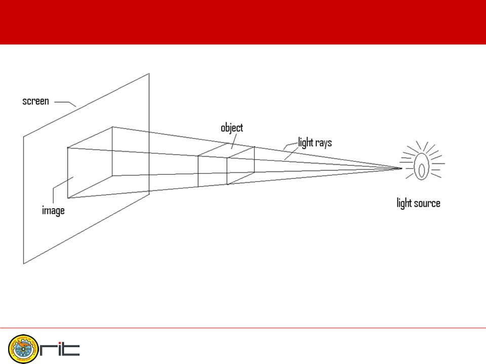
PROJECTION THEORY The projection theory is based on two variables: 1) Line of sight 2) Plane of projection (image plane or picture plane) The projection theory is used to graphically represent 3-D objects on 2-D media (paper, computer screen). 13

14
Line of sight Line of sight is an imaginary ray of light between an observer’s eye and an object. Line of sight Parallel projection 14

15
Plane of projection Plane of projection is an imaginary flat plane on which the image is created. The image is produced by connecting the points where the LOS (Light of sight) pierce the projection plane. Parallel projection Plane of projection 15
 pierce the projection plane. Parallel projection Plane of projection 15.")
16
Orthographic Projections It is a parallel projection technique in which the Lines of Sight (LOS) are perpendicular to the Plane of Projection Ortho –1 straight. 2 right.(Oxford Dictionary)Ortho –1 straight. 2 right.(Oxford Dictionary) 16
Ortho –1 straight. 2 right.(Oxford Dictionary) 16.")
17
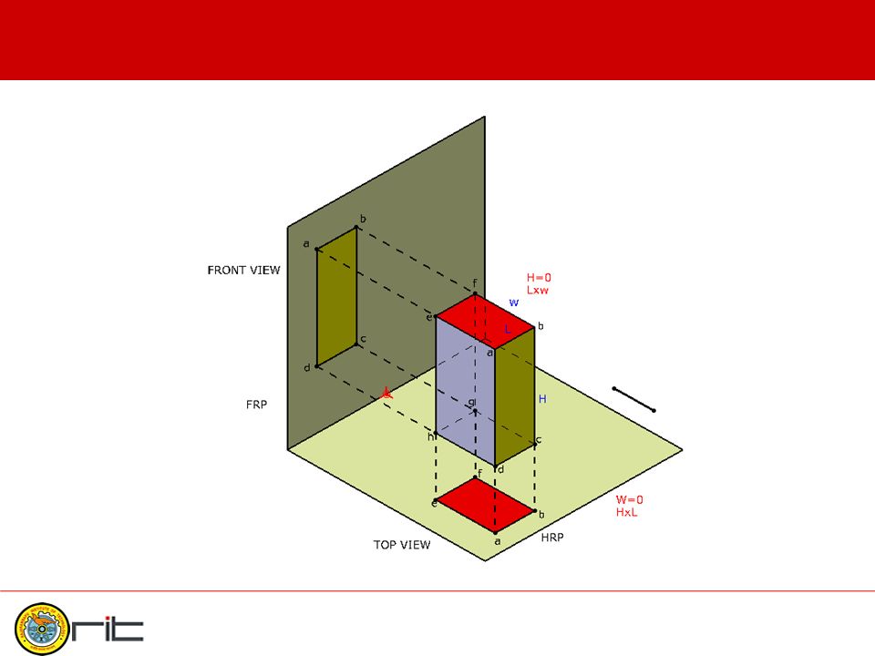
Planes of Projection Vertical Plane of Projection (V.P.) – Also called as Frontal Reference Plane (F.R.P.) – Projections obtained in FRP are called as Front View Horizontal Plane of Projection (H.P.) – Also called as Horizontal Reference Plane (H.R.P) – Projections obtained in HRP are called as Top View 17
 – Also called as Frontal Reference Plane (F.R.P.) – Projections obtained in FRP are called as Front View Horizontal Plane of Projection (H.P.) – Also called as Horizontal Reference Plane (H.R.P) – Projections obtained in HRP are called as Top View 17")
18
H.R.P F.R.P. H.R.P. and F.R.P.

20
Planes of Projection 90 0 H.R.P. F.R.P P.R.P X Y 20

21
Four Quadrants If the Planes of Projection are extended beyond the line of intersection (XY line) they form four quadrants. All planes are assumed to be transparent. 21

22
Four Quadrants 22

23
Methods of Projections First Angle Method – Object is kept in FIRST QUADRANT. Third Angle Method – Object is placed in the THIRD QUADRANT. 23

24
24

25
25

26
First Angle Method 26

27
First Angle Method 27

28
First Angle Method 28

29
First Angle Method 29

30
First Angle Method 30

31
First Angle Method- Conversion to 2D 31

32
32

33
FOR T.V. FOR S.V. FOR F.V. FIRST ANGLE PROJECTION IN THIS METHOD, THE OBJECT IS ASSUMED TO BE SITUATED IN FIRST QUADRANT MEANS ABOVE HP & INFRONT OF VP. OBJECT IS INBETWEEN OBSERVER & PLANE. ACTUAL PATTERN OF PLANES & VIEWS IN FIRST ANGLE METHOD OF PROJECTIONS X Y VP HP PP FVLSV TV

34
Third Angle Method 34

35
Four Quadrants 35

36
Third Angle Method 36

37
Third Angle Method 37

38
Third Angle Method 38

39
Third Angle Method 39

40
Third Angle Method H.R.P. F.R.P 40

41
Third Angle Method H.R.P. F.R.P 41

42
In this method, The object is assumed to be situated in third quadrant (Below HRP & behind of FRP) 42 Planes being transparent and in between Observer & object.
 42 Planes being transparent and in between Observer & object.")
43
Symbolic Representation

44
44 1. Principal surface 2. Inclined surface 3. Skew surface 4. Curved surface Types of Surfaces

45
45 The surface, which is parallel to one reference plane and perpendicular to other two, is referred as principal surface. It shows two line views and one area view as true area. Horizontal surfaces are always principal surfaces but not the vertical. Principal Surfaces

46
46 The surface, which is inclined to two reference planes and perpendicular to other, is referred as an inclined (or slant) surface. It shows one line view and two area-views with apparent size as shown in Figure. In this type of surface, at least one edge of the surface is along the principal axis. Inclined Surfaces

47
47 The surface, which is inclined to all three principal planes (HP, VP and PP), is referred as a skew (or oblique) surface. It shows 3 area- views with apparent size as shown in Figure. In this type of surface, none of the edge of the surface is along the principal axis. Skew Surfaces

48
48 The surface, which has constant radius such as arc or circle, is referred as curved (or rounded surface). Curved Surfaces In this type of surface, the last visible part of the curved surface falls in line view.

49
49 Concept of Hidden Line

50
50 Hidden Line Coincides with Visible Line

51
51 Last visible part of curved surface falls into a line view

52
52 Object as an Assembly

53
53 Object as a Single Piece

54
54 Object as a Single Piece

55
55 Assembly versus Single Piece Object

56
56 Precedence of Lines

57
57 Thickness 3 mm FV One View Drawing

58
58 Three View Drawing

59
59 Three View Drawing

60
Example 60

61
Example 61

62
Example 62

63
Example 63

64
Example 64

65
Example 65

66
Example 66

67
Example 67

68
Example 68

69
Example 69

70
Example 70

71
Example 71

72
Example 72

73
Example 73

74
Example 74

75
75

76
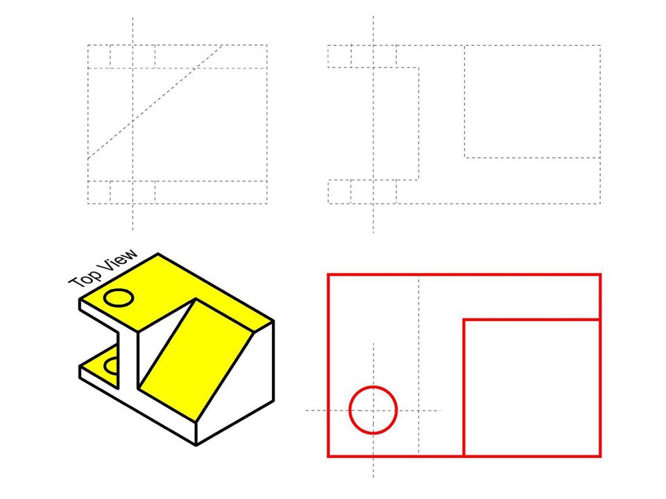
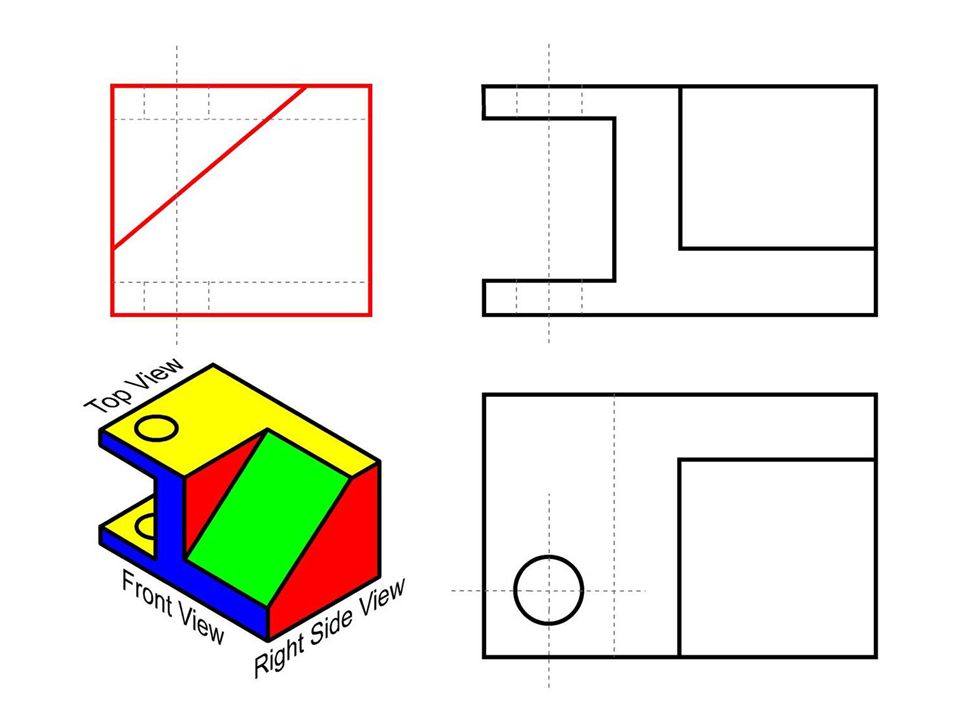
Fill in the visible lines into top view.

78
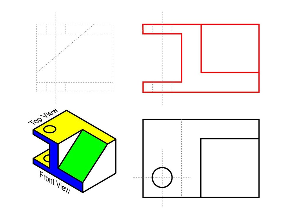
Fill in the visible lines in to front view.

80
Fill in the visible lines in to right side view.

82
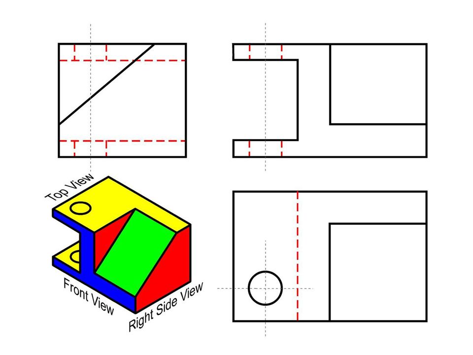
Fill in the hidden lines in to front, top and right side views.

84
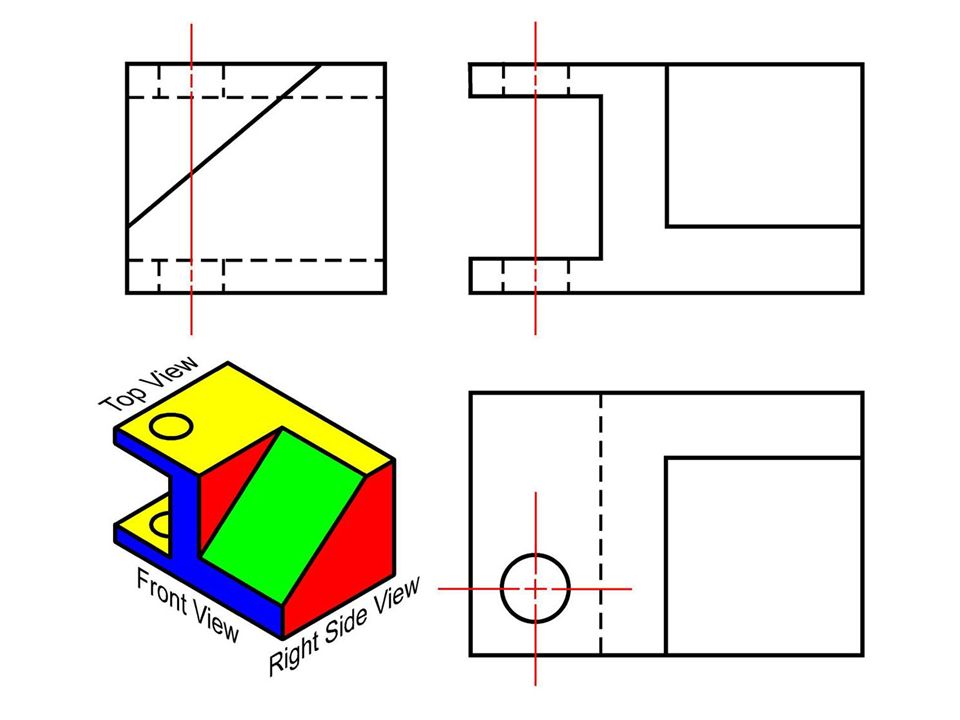
Draw the center lines in all the views.

86
37 10 63 20 37 25 8 14 40 10 19 8 10 X Y

88
Problem 13 F.E. (Graphics) - Nilesh Sabnis R20 14 80 10 D20 10 40 13 20 X 55
 - Nilesh Sabnis R D X 55")
Similar presentations


>")


>")


 The Fact about: If compared with Verbal or Written Description, Drawings offer far better idea about the Shape,>")
