Download presentation
Presentation is loading. Please wait.

2
Objective of Lecture State Thévenin’s and Norton Theorems. Chapter 4.5 and 4.6 Fundamentals of Electric Circuits Demonstrate how Thévenin’s and Norton theorems ca be used to simplify a circuit to one that contains three components: a power source, equivalent resistor, and load.

3
Thévenin’s Theorem A linear two-terminal circuit can be replaced with an equivalent circuit of an ideal voltage source, V Th, in series with a resistor, R Th. V Th is equal to the open-circuit voltage at the terminals. R Th is the equivalent or input resistance when the independent sources are turned off.

4
Circuit Schematic: Thévenin’s Theorem

5
Definitions for Thévenin’s Theorem Linear circuit is a circuit where the voltage is directly proportional to the current (i.e., Ohm’s Law is followed). Two terminals are the 2 nodes/2 wires that can make a connection between the circuit to the load.

6
Definitions for Thévenin’s Theorem Open-circuit voltage V oc is the voltage, V, when the load is an open circuit (i.e., R L = ∞ ). + V oc _

7
Definitions for Thévenin’s Theorem Input resistance is the resistance seen by the load when V Th = 0V. It is also the resistance of the linear circuit when the load is a short circuit (R L = 0 ).
..")
8
Steps to Determine V Th and R Th 1. Identify the load, which may be a resistor or a part of the circuit. 2. Replace the load with an open circuit. 3. Calculate V OC. This is V Th. 4. Turn off all independent voltage and currents sources. 5. Calculate the equivalent resistance of the circuit. This is R TH. The current through and voltage across the load in series with V Th and R Th is the load’s actual current and voltage in the originial circuit.

9
Norton’s Theorem A linear two-terminal circuit can be replaced with an equivalent circuit of an ideal current source, I N, in series with a resistor, R N. I N is equal to the short-circuit current at the terminals. R N is the equivalent or input resistance when the independent sources are turned off.

10
Definitions for Norton’s Theorem Open-circuit voltage I sc is the current, i, when the load is a short circuit (i.e., R L = 0 ).
.")
11
Definitions for Norton’s Theorem Input resistance is the resistance seen by the load when I N = 0A. It is also the resistance of the linear circuit when the load is an open circuit (R L = ∞ ).
..")
12
Steps to Determine I N and R N 1. Identify the load, which may be a resistor or a part of the circuit. 2. Replace the load with a short circuit. 3. Calculate I SC. This is I N. 4. Turn off all independent voltage and currents sources. 5. Calculate the equivalent resistance of the circuit. This is R TH. The current through and voltage across the load in parallel with I N and R N is the load’s actual current and voltage in the originial circuit.

13
Source Conversion A Thévenin equivalent circuit can easily be transformed to a Norton equivalent circuit (or visa versa). If R Th = R N, then V Th = R N I N and I N = V Th /R Th

14
Value of Theorems Simplification of complex circuits. Used to predict the current through and voltage across any load attached to the two terminals. Provides information to users of the circuit.

15
Example #1

16
Example #1 (con’t) Find I N and R N
 Find I N and R N")
17
Example #1 (con’t) Calculation for I N Look at current divider equation: If R Th = R N = 1k , then I N = 6mA
 Calculation for I N Look at current divider equation: If R Th = R N = 1k , then I N = 6mA")
18
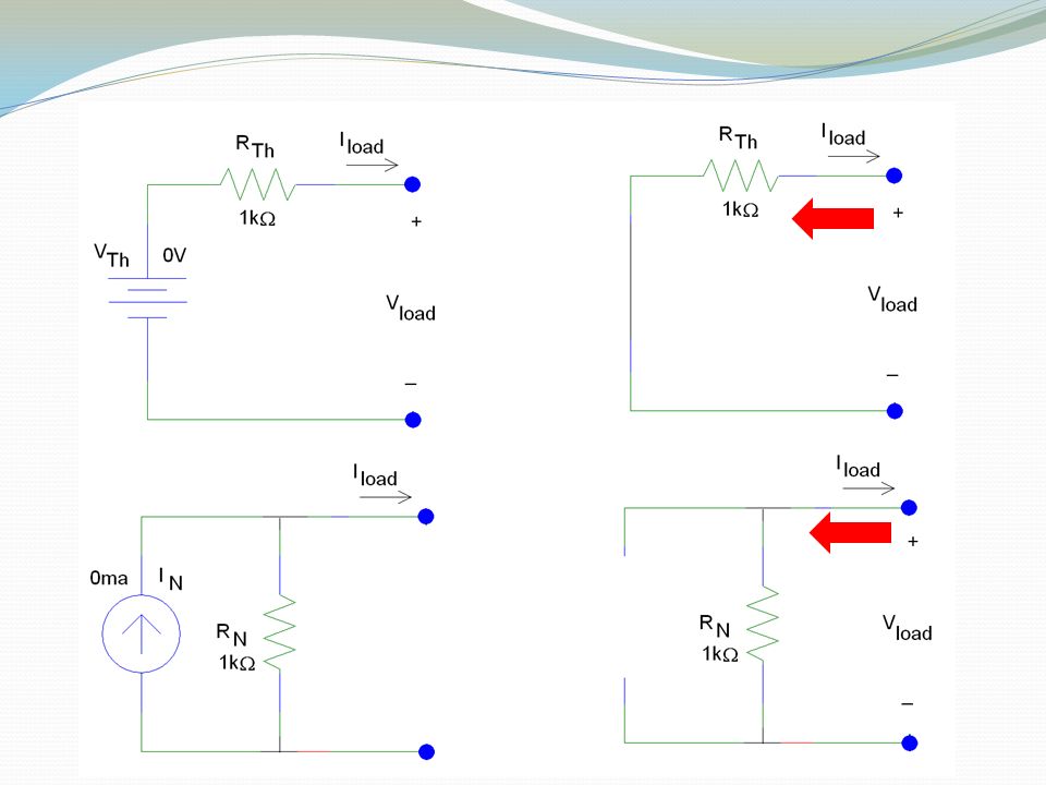
Why chose R Th = R N ? Suppose V Th = 0V and I N = 0mA Replace the voltage source with a short circuit. Replace the current source with an open circuit. Looking towards the source, both circuits have the identical resistance (1k ).
..")
20
Source Transformation Equations for Thévenin/Norton Transformations V Th = I N R Th I N = V Th /R Th R Th = R N

21
Alternative Approach: Example #1 I N is the current that flows when a short circuit is used as the load with a voltage source I N = V Th /R Th = 6mA

22
Alternative Approach V Th is the voltage across the load when an open short circuit is used as the load with a current source V Th = I N R Th = 6V

23
Example #2 Simplification through Transformation

24
Example #2 (con’t)
")
25
Current Source to Voltage Source

26
Example #2 (con’t) R Th = 3 V Th = 0.1A (3 ) = 0.3V 0.3V Current Source to Voltage Source
 R Th = 3 V Th = 0.1A (3 ) = 0.3V 0.3V Current Source to Voltage Source")
27
Example #2 (con’t) 0.3V
 0.3V")
28
Example #2 (con’t) R Th = 2 I N = 3V/2 = 1.5A Voltage Source to Current Source
 R Th = 2 I N = 3V/2 = 1.5A Voltage Source to Current Source")
29
0.3V Example #2 - Solution 1 Simplify to Minimum Number of Current Sources

30
Example #2 (con’t) R Th = 6 I N = 0.3V/6 = 50.0mA 0.3V Voltage Source to Current Source
 R Th = 6 I N = 0.3V/6 = 50.0mA 0.3V Voltage Source to Current Source")
31
Example #2 (con’t)
")
32
Current Sources in Parallel Add

33
Example #2 - Solution 2 Simplify to Minimum Number of Voltage Sources 0.3V

34
Example #2 (con’t) Transform solution for Norton circuit to Thévenin circuit to obtain single voltage source/single equivalent resistor in series with load.
 Transform solution for Norton circuit to Thévenin circuit to obtain single voltage source/single equivalent resistor in series with load.")
35
PSpice

36
Example #2 - Solution 1

37
Example #2 – Solution 2

38
Summary Thévenin and Norton transformations are performed to: Simplify a circuit for analysis Allow engineers to use a voltage source when a current source is called out in the circuit schematic Enable an engineer to determine the value of the load resistor for maximum power transfer/impedance matching.

Similar presentations


>")


