Download presentation
Presentation is loading. Please wait.

1
Train Body The next series of slides will guide you through the construction of the train body. Start a new drawing and save it as Train Body.

2
Now that we have reviewed the sketch, constraining, dimensioning, and extrusion process, let’s create the base feature of the train body. Refer to the IED Resource Guide for the dimensions.

3
Pick View, Toolbar, Sketch to activate the Sketching tools. Pick Line. 3

4
Pick this intersection and drag up. Current X,Y coordinates of cursor Current length of sketch line Current polar angle of sketch line from 0,0 User hints are given here. 4 © Project Lead The Way, Inc.

5
Sketch 3 lines Select 3 point Arc from the Sketch toolbar and pick start of Arc here. Select End of Arc here. Drag up to the right and pick another point. Right click and pick Done. 5 © Project Lead The Way, Inc.

6
Pick here. We will now dimension the rough profile using the General Dimension tool. Pick this line, then drag down and pick another point to place the dimension. When a dimension needs changing, double click it to bring up the Dim edit box. Key in the correct size and press Enter. 6 © Project Lead The Way, Inc.

7
This sketch is fully dimensioned. Any additional dimensions will result in the error message below. © Project Lead The Way, Inc.

8
Right click the drawing screen and pick Isometric View. 8 © Project Lead The Way, Inc.

9
Pick View and launch the Features Toolbar. Pick Extrude. 9 © Project Lead The Way, Inc.

10
Key in distance. Select the direction of Extrusion and pick OK. Extrusion Preview 10 © Project Lead The Way, Inc.

11
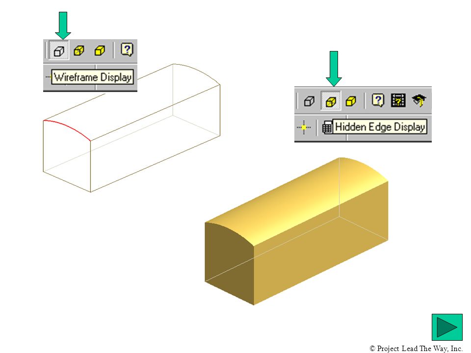
The base feature has successfully been extruded and displayed in Shaded mode. The next slide will demo two other display modes that may be useful in the future. Now would be a good time to save. Saving your work should be done after any major feature addition has been completed! © Project Lead The Way, Inc.

13
Pick Sketch, then pick this end of the extrusion. Notice the dark outline on the end of the extrusion. This is visual feedback that signifies a sketching surface is ready. Now we will apply a cut extrusion on the front end of the train body. © Project Lead The Way, Inc.

14
Pick Rectangle. Pick about here first, then drag to about here and pick a point, right click and pick Done. 14 © Project Lead The Way, Inc.

15
Only one dimension is needed Pick Extrude from the Features toolbar, then pick this rectangle. In the next slide we will adjust the size and type of extrusion. © Project Lead The Way, Inc.

16
First, set the distance. Second, select the direction. Third, set the Extrusion type to Cut and pick OK. © Project Lead The Way, Inc.

17
We will now build the tank on the front of the train body. Pick Sketch. Now, pick this face. 17 © Project Lead The Way, Inc.

18
Use the Rotate View function to maneuver train body for clarity. When the viewing direction is satisfactory, right click and pick Done. 18 © Project Lead The Way, Inc.

19
Sketch a circle approximately in this position, then dimension its diameter and X,Y location as illustrated to the right. © Project Lead The Way, Inc.

20
Set extrusion type to Join. Extent of extrusion is set at To. Select this surface to end the extrusion and pick OK. Save your work after extruding! 20 © Project Lead The Way, Inc.

21
Now we will drill the axle holes and extrude cut the cab. Pick Sketch and select the long side of the train body. 21 © Project Lead The Way, Inc.

22
For some sketch situations, it is helpful to look directly at the surface. We will do that now. Pick the Look At icon, and then pick the long surface of the train body. 22 © Project Lead The Way, Inc.

23
Sketch a circle and lines about here, trim and dimension as illustrated below. This will serve as the cutting profile. © Project Lead The Way, Inc.

24
Adjust settings in the Extrude dialog box as shown below. Then pick OK. Rotate the view and Cut Extrude the profile. © Project Lead The Way, Inc.

25
To improve clarity, the color, viewing angle, and display type have been changed. Now it’s time to locate the center points for the axle holes. © Project Lead The Way, Inc.

26
First, assign a sketch plane to this surface. Next, use Point, Hole Center to locate position of holes. © Project Lead The Way, Inc.

27
When finished marking the centers, right click and pick Done. Pick approximate location for each hole. In the next slide we will place dimensions. © Project Lead The Way, Inc.

28
Use the General Dimensioning tool to precisely locate the hole centers. Initial dimensions are red, double click to adjust values. Key in correct value and press Enter or pick green check mark. © Project Lead The Way, Inc.

29
Pick the Hole function from the Features toolbar. Adjust the settings as indicated by arrows below and pick OK. Save your work! 29 © Project Lead The Way, Inc.

30
In the next few slides, we will add the smoke stack to the top of the tank. Since there is no flat sketching surface on the tank, we first must place a work plane tangent to the tank and then offset it from the top surface of the cylinder. Switch to the isometric view. 30 © Project Lead The Way, Inc.

31
Pick Work Plane from the Features Toolbar. Next, pick the cylinder. 31 © Project Lead The Way, Inc.

32
Move the cursor along the cylinder until this workplane is previewed, then pick that plane to produce the workplane as pictured on the right. © Project Lead The Way, Inc.

33
We now will create an offset workplane from the original workplane. Select the Workplane icon from the Features toolbar. First, pick this workplane and drag up. Next, key in the offset value of 1 and press Enter. © Project Lead The Way, Inc.

34
The result is two work planes. We will now turn off the plane on the bottom by selecting it from the browser. © Project Lead The Way, Inc.

35
In the Browser, left click on the Work Plane name, then right click to produce the visibility prompt below Left click on Visibility, the result is shown on the right. © Project Lead The Way, Inc.

36
Switch to Top View of the tank using the Look At function. Pick this edge. Pick Sketch, then pick the edge of the work plane. © Project Lead The Way, Inc.

37
Sketch and dimension this circle. After sketching, switch to the isometric view. © Project Lead The Way, Inc.

38
Pick Extrude from the Features toolbar and set the parameters as shown below. Pick OK when done. The first tapered extrusion is done. Next, we will apply the tapered cap on top of the smoke stack. © Project Lead The Way, Inc.

39
In the Isometric view, select top of stack as sketch plane and sketch this circle. Next, constrain it with Concentric and Same radius constraints. Pick here to launch constraint toolbar. Concentric constraint Same constraint © Project Lead The Way, Inc.

40
Results of Concentric and Same radius constraints. © Project Lead The Way, Inc.

41
Pick Extrude from the Features toolbar and set up the parameters, as shown on the right. Pick OK when done. Now would be a good time to save! © Project Lead The Way, Inc.

42
From the Features toolbar, pick the Fillet icon. © Project Lead The Way, Inc.

43
Pick edge to identify the first loop, then pick OK. Rotate model and repeat as needed. Use the Loop option when applying fillets around a face. It is much faster than single edge picking. To fillet the intersection of 2 or more surfaces, use the Edge select mode. Key in a value of 0.100. © Project Lead The Way, Inc.

44
Completed Train Body Save your work! 44 Index © Project Lead The Way, Inc.

45
Wheel Start a new drawing and save it as Wheel. The next series of slides will guide you through the construction of the train wheel. © Project Lead The Way, Inc.

46
For units in inches, pick English. Pick Standard (in).ipt, then pick OK. The.ipt file extension is used for single Inventor part files. © Project Lead The Way, Inc.

47
Pick here to maximize the drawing space. Save this startup sheet as Wheel. Enter filename and pick Save. 47 © Project Lead The Way, Inc.

48
Pick View, Toolbar, Sketch to activate the Sketching tools. Sketch this figure and apply dimensions as in the figure to the right. 48 © Project Lead The Way, Inc.

49
Switch to the Isometric View. Pick Revolve. © Project Lead The Way, Inc.

50
You must first pick a line on the profile that will serve as the centerline of rotation. Set Extents to Full and pick OK. © Project Lead The Way, Inc.

51
Pick Sketch, then pick surface indicated below. Pick this icon to mark the center for the axle hole. © Project Lead The Way, Inc.

52
Adjust the settings as indicated by arrows Below, and pick OK. SAVE YOUR WORK! 52 © Project Lead The Way, Inc.

53
The next group will demonstrate how to add the link pin post. Select the lower surface for the Sketch plane. Use the Look At function to view straight on. © Project Lead The Way, Inc.

54
Sketch and dimension this circle, then switch to the Isometric View. Activate Extrude and pick this profile. Set up the dialog box using the values on the left and pick OK. © Project Lead The Way, Inc.

55
Set the Sketch plane to the top of the peg and sketch and dimension as given on the right. Make sure to apply a concentric constraint. © Project Lead The Way, Inc.

56
Set up dialog box as indicated above and pick OK. The last operation on the wheel will be to drill a hole here for the link pin fastener. © Project Lead The Way, Inc.

57
Set the Sketch plane to the end of the pin. Locate the hole center here. Use this function to place the hole center. © Project Lead The Way, Inc.

58
Adjust settings as above and pick OK. Save your work! © Project Lead The Way, Inc.

59
Adding a Work Axis We first have to put hole centers in both holes on the correct sketch plane. First, pick Sketch. Pick the inner circular edge for the sketch plane. © Project Lead The Way, Inc.

60
Pick Hole Center. Then pick this Intersection. This is a Zoomed view of the center mark. © Project Lead The Way, Inc.

61
Launch the Features toolbar from the View menu. Pick Work Axis. 61 © Project Lead The Way, Inc.

62
First, pick the center. Next, pick this circular edge. A vertical axis should appear. Later, we will use this axis to animate the wheel linkages. 62 Save your work! Index © Project Lead The Way, Inc.

63
Axle Peg Start a new drawing and save it as Peg. The next series of slides will guide you through the construction of the axle peg. © Project Lead The Way, Inc.

64
Sketch and dimension a circle. Adjust settings in the Extrude dialog box as shown below. Then pick OK. © Project Lead The Way, Inc.

65
Now we will put a cap on the tapered peg. To do this, a sketch plane on the YZ axis going through the center of the peg must be applied. Follow the steps below. Pick the plus sign to expand the origin. Then pick here. © Project Lead The Way, Inc.

66
Pick Sketch. Rotate view until this axis is near horizontal. © Project Lead The Way, Inc.

67
Sketch and dimension the figure on the right. Sketch two lines, then use 3 point arc. Dimension as shown. Finally, use the Revolve function to complete the cap. © Project Lead The Way, Inc.

68
Pick this line as Centerline of rotation. Set Extents to Full and pick OK. Save your work! Index © Project Lead The Way, Inc.

69
Linkage Arm The next series of slides will guide you through the construction of the linkage arm. We will make use of the adaptive sketch and adaptive extrusion functions. Start a new drawing and save it as Linkage Arm. © Project Lead The Way, Inc.

70
Sketch this figure. Trim until it looks like this on both ends. Apply dimensions as given on the left, and switch to the Isometric View. The distance between the arcs is not needed, as this will be left free to Adapt to the assembly in a later step. © Project Lead The Way, Inc.

71
Set the dialog box values as given on the left and pick OK. Place Hole Centers as shown in preparation for drilling holes. © Project Lead The Way, Inc.

72
Adjust the settings shown in the dialog box and pick OK. The next slide will demonstrate how to make the link adapt to the changing needs of an assembly. © Project Lead The Way, Inc.

73
Right click Extrusion1 in the Browser. Select Adaptive, then observe the Adaptive symbol next to Extrusion1 in the Browser. When you Right click Extrusion1 in the Browser, then pick Properties. You will get the dialog box below. Remember, any undimensioned sketch geometry such as length, diameter, and extrusion thickness, can be made adaptive to meet assembly constraints. Save Your Work! Index © Project Lead The Way, Inc.

74
Link Pin The next series of slides will guide you through the construction of the link pin. Start a new drawing and save it as Link Pin. © Project Lead The Way, Inc.

75
Second, switch to the Isometric View and Zoom in as needed. First, sketch and dimension this circle. Finally, pick Extrude and change the values as given in the dialog box on the right. Then pick OK. © Project Lead The Way, Inc.

76
Now we will put a cap on the tapered peg. To do this, a sketch plane on the YZ axis going through the center of the peg must be applied. Follow the steps below. Pick the plus sign to expand the origin. Then pick here. © Project Lead The Way, Inc.

77
Pick Sketch. Rotate view until this axis is near horizontal. © Project Lead The Way, Inc.

78
Sketch and dimension the figure on the right. Sketch two lines, then use 3 point arc. Dimension as shown. Finally, use the Revolve function to complete the cap. See how in the next slide. © Project Lead The Way, Inc.

79
Pick this line as Centerline of rotation. Set Extents to Full and pick OK. Index © Project Lead The Way, Inc.

80
Close up Orthographic views follow this image. © Project Lead The Way, Inc.

81
Top View Curved Track © Project Lead The Way, Inc.

82
Top View Curved Track © Project Lead The Way, Inc.

83
Front View Curved Track © Project Lead The Way, Inc.

84
Close up Orthographic views follow this image. © Project Lead The Way, Inc.

85
Top View Straight Track © Project Lead The Way, Inc.

86
Top View Straight Track © Project Lead The Way, Inc.

87
Front View Straight Track © Project Lead The Way, Inc.

Similar presentations