Download presentation
Presentation is loading. Please wait.

1
PROCESSING THE IMAGE SENSITOMETRY WEEK 12 - 2006
RTEC 244 PROCESSING THE IMAGE SENSITOMETRY WEEK

2
THE DARKROOM

3
Darkroom

4
Darkroom Equipment

5
SAFELIGHTS

6
Safe Light 15 Watts Red filter
Must be 3-6 feet from counter top or feed tray of processor Used to be amber or orange filter

10
DEVELOPER FIXER WASH DRY WATER - SOLVENT

11
AUTOMATIC PROCESSING CHEMICALS

12
What is in the Darkroom?

13
Darkroom

14
Darkrooms – Still Necessary?
Darkrooms are necessary for manually fed processors And daylight processors. -Loading automatic (daylight) film processor magazines. Necessary for conducting certain quality control tests (daily sensitometric strip).To check consistency of processing
 film processor magazines. Necessary for conducting certain quality control tests (daily sensitometric strip).To check consistency of processing.")
15
Darkrooms 4 Basic Functions
Number 1 Function Storage Unexposed film

16
Film Bin

17
Darkroom Contents Loading Bench Film Bin Film I.D. Printer Safelights
Pass Box Light-tight Room Ample ventilation Warning Light outside room Lockable Door Wall Shielding if adjacent to x-ray room Walls painted with light color to reflect safelight

20
Purpose of Film Processing
DARKROOM FUNCTION # 2 Purpose of Film Processing Change silver halide crystals from film emulsion (after exposure to x-ray or light photons) to black metallic silver. Latent image (invisible until processed) is developed into a Manifest image. Improper or careless processing can cause poor diagnostic quality.
 to black metallic silver. Latent image (invisible until processed) is developed into a Manifest image. Improper or careless processing can cause poor diagnostic quality.")
21
Manual Feed Processor

22
Processing Film

23
TABLE TOP PROCESSOR

25
Function # 4: Film Identification
Pt name Exam date & time Pt x-ray number Pt Birthday/DOB Rt or Lt marker Optional Exam type Dr. Name

26
FILM ID PRINTER In Daylight in Darkroom Cassette Flashed Film Flashed

28
Daylight Processor

30
WILL THIS WORK ????

31
Function # 3: Handling of Film

32
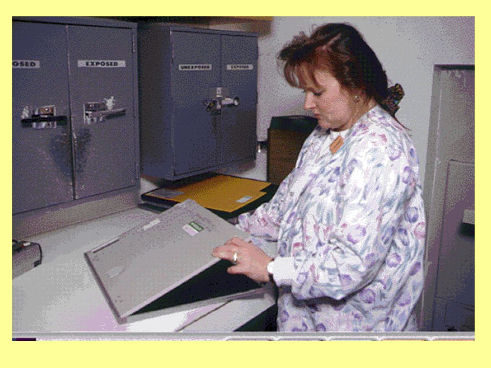
UNLOAD EXPOSED FILM

33
Basic Recommendations Now done by Processor Co.
Follow mfg. recommendations: -strength of chemicals -temperature of chemicals -time requirements in each chemical Solutions should be replenished as necessary & changed regularly Solutions must be monitored (Daily QC strip).
.")
34
CHEMICAL FOG strength of chemicals in DEVELOPER
DILUTE – Under Processed (light films) OXIDIZED - over processed (films dark) temperature of chemicals Too Hot - films dark time requirements in each chemical Too long in tanks – films dark
 OXIDIZED - over processed (films dark) temperature of chemicals. Too Hot - films dark. time requirements in each chemical. Too long in tanks – films dark.")
35
Chemcial Fog diluted or contaminated chemisty

36
Strength of Chemisty can affect outcome radiograph

37
AUTOMATIC PROCESSING WASHER DEVELOPER DRYER FIXER REPLENISHMENT SYSTEM
TRANSPORTATION SYSTEM DEVELOPER FIXER WASHER DRYER REPLENISHMENT SYSTEM

38
Automatic Processor

39
Processor Chemistry Overview
Developer – converts latent image into manifest image Fixer – clear the film of unexposed, undeveloped silver bromide crystals, promotes archival quality Wash – rid the film of residual chemicals Dry - sets the film for handling

40
Developer Solution (6 Ingredients)
Reducing Agent: reduce exposed silver halide to black metallic silver -Hydroquinone (Blacks) SLOW -Phenidone (Grays) FAST (Metol or Elon) 2. Activator: softens gelatin, maintains alkaline pH (increase pH) -Sodium Carbonate
 SLOW. -Phenidone (Grays) FAST. (Metol or Elon) 2. Activator: softens gelatin, maintains alkaline pH (increase pH) -Sodium Carbonate.")
41
Developer Solution 3. Hardener: prevents damage to the film from over swelling of gelatin in automatic processors. -Gluteraldehyde 4. Preservative: Antioxidant that prevents oxidation of developer -Sodium Sulfite

42
Developer Solution 5. Restrainer: prevents chemical fog in new developer – antifogging agent -Potassium Bromide (In starter solution) 6. Solvent: dissolves & ionizes the developer chemicals -Water
 6. Solvent: dissolves & ionizes the developer chemicals. -Water.")
43
Fixer Solution (5 Ingredients)
Clearing Agent: dissolves /removes undeveloped silver halide crystals -Ammonium Thiosulfate (Fixer retention – film turns brown if not washed off) Activator: stops reduction, acidic pH ACETIC ACID
 Activator: stops reduction, acidic pH. ACETIC ACID.")
44
FIXER SOLUTION Hardener: harden emulsion POTASSIUM ALUM
(if films come out “sticky” this is depleted – it is not because of the dry not drying the films) 4. Preservative - maintains pH levels SODIUM SULFITE 5. Solvent: dissolves chemicals
 4. Preservative - maintains pH levels. SODIUM SULFITE. 5. Solvent: dissolves chemicals.")
45
Wash Rid the film of residual chemicals
Residual chemicals on the film will discolor radiograph over time. Cold water processors are less efficient in removing chemicals – Warm water processors much better. Agitation during wash process is essential

46
DRY removes water, seals emulsion Hot Air

47
Transport System Components
Feed Tray Rollers (Different Assemblies): 1. Entrance 2. Deep Racks 3. Turnaround 4. Crossover 5. Squeegee 6. Dryer Receiving Bin
: 1. Entrance. 2. Deep Racks. 3. Turnaround. 4. Crossover. 5. Squeegee. 6. Dryer. Receiving Bin.")
48
Transport System (Rollers)
Entrance Crossover Feed Tray Squeegee Deep Racks Dryer Turnaround

49
Replenishment System Main function: Keep solution tanks full and assure proper solution concentration. As film is introduced into processor, sensor initiates solution replenishment Right & wrong way to feed in film -Feed in along short edge Crosswise not lenghtwise (except 8x10) to not use up extra replensher
 to not use up extra replensher.")
50
Transport System in Automatic Processors
Conveys the film through different solutions (sections) by a series of rollers driven by gears, chains & sprockets. Done at a prescribed speed – determines length of time the film is in each solution
 by a series of rollers driven by gears, chains & sprockets. Done at a prescribed speed – determines length of time the film is in each solution.")
52
Temperature Regulation
Main function: To control the temperature of each section of the processor. Developer – most important solution to regulate Usually between 92 degrees and 95 degrees Thermostatically controlled Water circulation helps to control temp – if water is not turned on – processor temp will rise

53
Recirculation System Provides agitation necessary for uniform solution concentration

54
Wash & Dryer Systems Wash: Provide thorough removal of chemical solutions from the film. -Archival film quality Dryer: Removes water from film by blowing warm, dry air -Between 120 degrees & 130 degrees F.

55
Darkroom Summary

56
ARTIFACTS CAUSED BY PATIENT IMPROPER HANDLING / STORAGE
PROCESSING PROBLEMS

57
ARTIFACTS – An unwanted density on a film
can appear as a dark or light mark on the film (image) Caused by: Improper: Handling, Processing or Storage
 Caused by: Improper: Handling, Processing or Storage.")
58
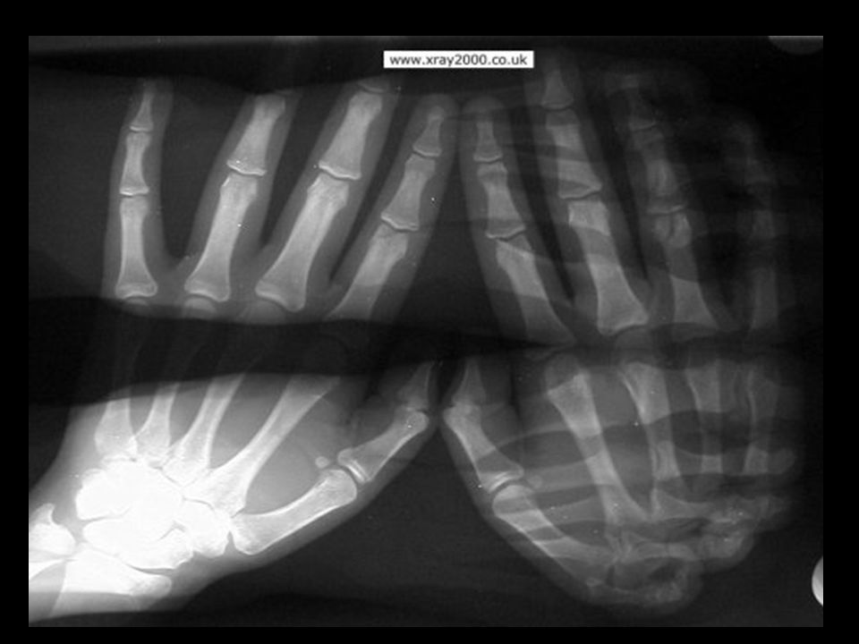
Artifact are undesirable an unwanted density on film
is the term for markings or images that appear on the finished film that did not result from the attenuation of the x-ray beam passing through the patient. They may appear because of poor conditions related to the film, mishandling, or processing problems. Artifacts can cause an image to be misinterpreted, can make interpretation difficult or impossible (as in the images shown in the illustration), and may require a repeat procedure resulting in unnecessary additional patient exposure.
, and may require a repeat procedure resulting in unnecessary additional patient exposure.")
59
Different kinds of artifacts can occur, but virtually all can be prevented. Fog artifacts can be caused by high temperatures, bright light, high humidity, or ionizing radiation. Scratches or pressure on the film can cause white or dark areas. Poor contact between the screen and film can cause localized blurring or darker areas. Dirt on the screen or film can cause white spots. Damaged cassettes or screens can cause a range of artifacts, as can improperly functioning automatic processors. Shown in the illustration are films marred by a variety of artifacts. Only by following accepted and safe procedures for handling and storing film, and for processing exposed film, can artifacts be prevented.

60
patient artifacts

61
ARTIFACTS AN UNWANTED DENSITY ON THE FILM

62
FIXER RETENTION (FIXER NOT WASHED OFF)
")
63
POOR SCREEN CONTACT

66
Blurring = Motion vs Poor screen contact

67
PATIENT ARTIFACT - JEWERLY

68
Crimping /cresent mark

69
Developer splashed on unprocessed film

70
Double exposure

71
Fogged film

72
Water spot

73
Hypo (fixer) retention
 retention")
74
Kink / cresent mark WHITE MARK – FILM BENT BEFORE EXPOSURE
(SILVER SEPARATES) DARK MARK – FILM BENT AFTER EXPOSURE SILVER MOVES TOGETHER
 DARK MARK – FILM BENT AFTER EXPOSURE. SILVER MOVES TOGETHER.")
75
ROLLER MARKS

76
ROLLER MARKS VS SCRATCHES
ROLLER MARKS – USUALLY DARK PERPEDICULAR TO FILM TRAVEL – THE WAY THE FILM IS PLACED ON THE FEED TRAY SCRATCHES – LIGHT PARALLEL TO FILM TRAVEL

77
SCRATCHES

78
DIRT IN SCREEN – WHITE MARK

79
STATIC = LOW HUMIDITY

80
Careful Handling a must

81
REFLECTED

84
scratch

85
Artifact

87
PATHOLOGY NOT ARTIFACT

91
Silver recovery

92
Silver Recovery About ½ of the film’s silver remains in the emulsion after exposure & processing. Other ½ (unexposed silver) is removed from the film during fixing process. Silver is toxic to public water supply – must have proper disposal.
 is removed from the film during fixing process. Silver is toxic to public water supply – must have proper disposal.")
93
SILVER RECOVERY – Photography consumes approximately 30% of the worlds sliver - half of this is used in diagnostic imaging films 3 reasons for Diagnostic Imaging Department to use silver recovery: 1. Dwindling worldwide supply of silver 2. $$ cash for silver ( school’s processing services donated for silver recovery) (About 10% of the films cost is recovered through silver recover) 3. State and Federal pollution regulations One of the functions of the fixer solution is to remove the unexposed and undeveloped silver halide crystals from the film. These crystals are eliminated with the used fixer by the replenishment system. The dissolved silver averages about 50% of the silver that was originally on the film.
 (About 10% of the films cost is recovered through silver recover) 3. State and Federal pollution regulations. One of the functions of the fixer solution is to remove the unexposed and undeveloped silver halide crystals from the film. These crystals are eliminated with the used fixer by the replenishment system. The dissolved silver averages about 50% of the silver that was originally on the film.")
95
Three methods of recovery:
1. Metallic Replacement - Steel wool inside a canister collects the silver (most useful type of recovery for low volume processors) 2. Electrolytic - cells pass an electric current through a cylinder, causing silver to be plated onto the cathode cylinder of the unit. Silver is removed by scraping it off the cathode. (For medium to high volume) 3. Chemical Precipitation - (oldest form) Chemicals cause a separation of the silver form the fixer. The silver sinks to the bottom and forms a sludge where it can be removed. (This is the least desirable way - hazardous chemicals used with toxic fumes) ( Only used by very large institutions) SILVER RECOVERY FROM FILM:
 2. Electrolytic - cells pass an electric current through a cylinder, causing silver to be plated onto the cathode cylinder of the unit. Silver is removed by scraping it off the cathode. (For medium to high volume) 3. Chemical Precipitation - (oldest form) Chemicals cause a separation of the silver form the fixer. The silver sinks to the bottom and forms a sludge where it can be removed. (This is the least desirable way - hazardous chemicals used with toxic fumes) ( Only used by very large institutions) SILVER RECOVERY FROM FILM:")
96
Green film - contains most of the silver (should be separated from other film) this film is worth more than developed film Scrap Film & Archival Film - Silver can be removed by burning the film and removing silver from the ashes, or using chemical treatments. Usually paid on a price per pound of film

97
There are three types of silver recovery systems: metallic replacement units, electrolytic units, and chemical precipitation units. In metallic replacement units, the used fixer circulates through a tank in which iron molecules in steel screens break down and are replaced by metallic silver precipitates. This method is less efficient than other methods and is less commonly used. In electrolytic units, such as the one shown in the illustration, an electric current is passed through the fixer; ionized silver molecules in the fixer are attracted to, and form a plating on, the negatively-charged rotating cathode. Other units use a process of chemical precipitation in which other chemicals react with the silver in the fixer solution. Silver molecules are freed and precipitate out of the solution, falling to the bottom of the tank where they can be recovered from the silver sludge that forms.

98
silver recovery. A final consideration in film processing is silver recovery. This term is the process by which silver in the processing chemicals is reclaimed and recycled by a unit, such as the one shown in the illustration. This recycling is important for two reasons. Silver has economic value in its recycled form and helps recover some of the cost of the unexposed film, which is expensive, in part, because of the silver in it. Secondly, federal regulations require that heavy metals like silver be reclaimed from waste solutions before they are disposed of, to prevent pollution of the environment. Roughly half the silver in the film ends up dissolved in the fixer in the automatic processor. Different kinds of silver recovery units are used to process the used fixer to recover the silver.

99
First, the film is fed into the unit through a feed tray in a conventional unit or directly from the cassette in daylight systems. The film first enters the developer tank. The developer solution gives up electrons that neutralize the positively charged silver ions in the film in a process called reduction. The chemical in the developer solution responsible for this is called the reducing agent. Metallic silver builds up in visible black specks at the sensitivity specks. Other chemicals in the developer help control this process precisely and prevent overexposure. A hardener also prevents the film emulsion from becoming too soft or swollen during the processing. To obtain the best visible image, the development process depends on precise control of the concentration and temperature of the developer, as well as the length of time the film is in the developer. All these are controlled automatically by the film processor.

100
Why does x-ray film come out black?
There are five possible reasons: The film is overexposured (exposures are too long or the setting is too high). The processing times are too long. The temperature is too warm. The film has been exposed to another light source. The safelight lens (filter) is cracked or damaged.
. The processing times are too long. The temperature is too warm. The film has been exposed to another light source. The safelight lens (filter) is cracked or damaged.")
101
QUESTIONS ??

102
X-ray film scanner Turns an analog image into an electronic image
See Ch. 43

103
Digital – Reverse Image

104
CASSETTES / FILM AND INTENSIFYING SCREENS
RT 244 REVIEW CASSETTES / FILM AND INTENSIFYING SCREENS

105
FILM SIZES 14 X 17 11 X 14 10 X 12 8 X 10

106
Film Sizes Standard “inches”: 8” x 10” 10” x 12” 11” x 14” 14” x 17”
Metric: 18cm x 24cm 24cm x 30cm 30cm x 35cm 35cm x 43cm

107
X-Ray Film Film is a media that makes a permanent record of the image.
Image recorded on film is caused by exposure to energy: -X-ray energy converted to light energy -Image before processing = Latent image -Made visible by chemical processing

108
X-ray Film cont’d Radiographic film is/was most common image receptor
Two parts: 1. Base 2. Emulsion

109
Film Construction Made of a polyester plastic
Must be clear, strong, consistent thickness Tinted pale blue or blue-gray (reduces eye strain) Photographic emulsion can be on one side or both sides of base (single emulsion / double emulsion) Protective overcoat layered on top of emulsion
 Photographic emulsion can be on one side or both sides of base (single emulsion / double emulsion) Protective overcoat layered on top of emulsion.")
110
FILM COMPOSTION SINGLE OR DOUBLE EMULSION EMULSION : GELATIN
COATED ON A BASE EMULSION : GELATIN WITH SILVER HALIDE CRYSTALS BASE: SUPPORT POLYESTER

112
Film Emulsion Made of mixture of gelatin & silver halide crystals (fluorine, chlorine, bromine, & iodine) Most x-ray film emulsions made of : silver bromide (90%) silver iodide (10%) Photographically active layer – activated by light & radiation to create image
 silver iodide (10%) Photographically active layer – activated by light & radiation to create image.")
114
X-Ray Film Cross Section

117
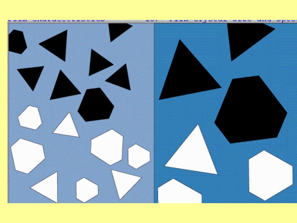
Film Characteristics Size of silver halide crystals & emulsion thickness determine speed of film and degree of resolution Larger crystals / thicker crystal layer =Faster response, less detail, less exposure (chest x-ray) Finer crystals / thinner crystal layer =Slower response, greater detail, more exposure (extremity)
 Finer crystals / thinner crystal layer. =Slower response, greater detail, more exposure (extremity)")
119
FIRST “FILM” GLASS PLATES WW 1 CELLULOSE ACETATE HIGHLY FLAMMABLE EASILY TORN RESPONSIBLE FOR MANY FIRES IN HOSPITAL BASEMENTS

120
X-ray Film Sensitivity
Light X-rays Gamma Rays Gases Fumes Heat Moisture Pressure Static Electricity Age So what happens??

121
FILM FOG!!!! Unintended uniform optical density on a radiograph because of x-rays, light, or chemical contamination that reduces contrast.

123
Film Storage Clean, dry location 40 degrees – 60 degrees Fahrenheit
Away from chemical fumes Safe from radiation exposure Standing on edge Expiration date clearly visible

124
Film latitude

125
FILM BIN - STORAGE

127
Spectral Sensitivity Film is designed to be sensitive to the color of light emitted by the intensifying screens. Blue LIGHT– Conventional Calcium Tungstate screen Green, Yellow-Green LIGHT – Rare Earth screen

128
Cassettes Cassettes serve 3 important functions:
Protect film from exposure to light Protect film from bending and scratching during use. Contain intensifying screens, keeps film in close contact to screen during exposure.

129
CASSETTE or FILM HOLDER
The CASSETTE is used to hold the film during examinations. It consist of front and back intensifying screens, and has a lead (Pb) backing. The cassette is light tight
 backing. The cassette is light tight.")
130
Cassette Features - Front
Exposure side of cassette is the “front”. Has the ID blocker (patient identification) Made of radiolucent material – easily penetrated by x-rays, lightweight metal alloy or plastic material made of resin. Intensifying screen mounted to inside of front.
 Made of radiolucent material – easily penetrated by x-rays, lightweight metal alloy or plastic material made of resin. Intensifying screen mounted to inside of front.")
132
Cassette Features - Back
Back made of metal or plastic Inside back is a layer of lead foil – prevents backscatter that could fog the film Inside foil layer is a layer of padding – maintains good film/screen contact Back intensifying screen mounted on padding

133
Intensifying Screens Flat surface coated with fluorescent crystals called phosphors that glow, giving off light when exposed to x-rays.

134
Intensifying Screens Reduce patient exposure Increase x-ray tube life
Direct x-ray exposure to film requires 25 to 400 times more radiation than film/screen. Two advantages to using intensifying screens: Reduce patient exposure Increase x-ray tube life

135
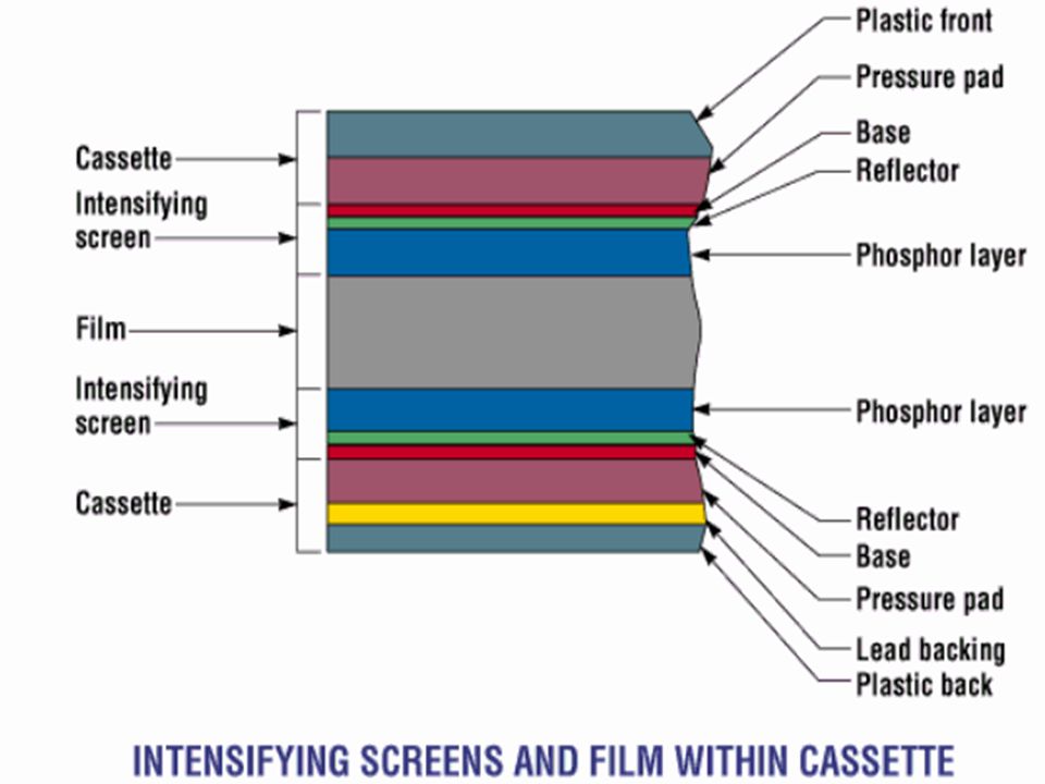
Screen Construction Polyester plastic base – support layer
Phosphor layer – active layer Reflective layer – increases screen efficiency by redirecting light headed in other directions Protective coating

136
Phosphor Layer Active layer – x-ray photons converted to light photons
*Photoelectric Effect Type must correlate with film: -Calcium Tungstate = blue to purple light -Rare Earth = green & ultraviolet light NAMES 3 ?

137
Rare Earth Screens Gadolinium Lanthanum Yttrium
Found in low abundance in nature

138
Intensifying Screen & Film Cross Section

139
Screen Speed Efficiency of a screen in converting x-rays to light is Screen Speed.

140
Screen Speed Greater efficiency = less exposure = faster
-Standard screen speed class of 100 -200 screen speed is twice as fast Speeds for routine work: 200 – 800 Speeds for high detail:

141
SCREEN SPEEDS FASTER SPEED – REDUCES PATIENT EXPOSURE
FASTER SPEED - REDUCES IMAGE DETAIL (LIGHT BLURING AROUND IMAGE)
")
149
SAFELIGHTS

150
FILM ID PRINTER

153
UNLOAD EXPOSED FILM

155
LOAD CASSETTE

157
Next Week – Processing the Image

158
QUESTIONS ?

159
Chapter 21 Film Sensitometry

160
Objectives Calculate speed points, speed exposure points and relative speeds from D log E curves Calculate gamma, gradient point, average gradient and latitude from D log E curves

161
Objectives Analyze D log E curves to determine speed, contrast and latitude relationships Discuss the relationships between speed, contrast and latitude

162
Sensitometry Measures the response of film to exposure and processing

163
Sensitometric Equipment
Penetrometer or sensitometer Used to create a uniform set of densities on a film Densitometer Provides measurement of light transmitted through film Measures optical density

164
Penetrometer Stepwedge Used to monitor x-ray equipment
Also used to monitor film/screen combinations Not recommended for processor monitoring

165
Sensitometer Uses a controlled light source
Produces same amount of light each time it is triggered

166
Sensitometer Available in 11- or 21- step versions
21 step version increases density by a factor of the square root of 2 (1.41) for each step
 for each step.")
167
Densitometer Uniform light source and an optical sensor
Calibration control allows for easy calibration

168
Optical Density Numbers
Formula: OD=log10 Io/It If 100% of the light is transmitted through the film, it has an OD of 0 If none of the light transmits through film the OD is 4

169
Opacity Ability of a film to stop light transmission Formula: Io/It

170
The D Log E Curve Describes relationship between density and exposure
This is done through sensitometry

171
The D Log E Curve AKA Sensitometric curve Characteristic curve Hurter and Driffield (H & D) curve Sensitometry’s roots lie in analysis of photographic film

172
The Sensitometric Curve
Plots OD vs. LRE Log relative exposure Allows large range of exposure displayed in a few numbers

173
The Sensitometric Curve
Log relative exposure Log102 represents doubling exposure Log102 = 0.3

174
Densitometer Reads on a scale of 0-4
0 meaning that all light is transmitted 4 meaning that no light transmits through the film Typical diagnostic densities range between 0.25 to 2.5

175
Parts of the Curve Base + fog Toe-Dmin Straight line portion
Where the density becomes light Straight line portion Used to demonstrate the relationship to the film’s exposure vs. the density transmitted

176
Parts of the Curve Shoulder-Dmax Where the density becomes dark

177
Film Properties Base density Fog Density
Inherent in a piece of film due to dyes etc. Value is usually 0.1 OD Fog Density Inadvertent exposure during storage handling etc. Fog density should not exceed 0.2 OD

178
Base + Fog Cannot separate base and fog density measurements
Typical range of OD for Base + fog 0.18 to 0.23 Should not exceed 0.25

179
Toe Dmin Controlled by phenidone
Fast acting reducing agent in developer Produces gray tones on film

180
Straight Line Portion Area of curve between toe and shoulder
Contains range of useful densities Typically 0.25 – 2.5 or 3.0

181
Shoulder Dmax Controlled by hydroquinone
Slow acting reducing agent in developer Produces blacks in image

182
Reversal or Solarization
Once a film has been exposed to Dmax, it will begin to lose density after further exposure Duplication film has been solarized

183
Film Characteristics Resolution Speed Contrast Latitude

184
Resolution Ability to accurately image an object AKA Detail Sharpness
Definition Resolving power

185
Resolution Inversely related to size of silver halide crystals

186
Speed Ability of an IR to respond to low exposure measures its sensitivity or speed Speed index Specified by base + fog

187
Speed Faster film will have a curve closer to y-axis of graph

188
Speed Film sensitivity is affected by:
Size of silver halide crystals Number of sensitivity specks Thickness of the emulsion All of the above are directly related to film speed

189
Speed Affected by processing Immersion time Solution temperature
Chemical activity

190
Speed

191
Contrast Contrast is controlled by hydroquinone
Hydroquinone establishes the shoulder Thus, it affects slope of the straight line portion of curve

192
Film Contrast and Curve
Film contrast is defined by straight line portion of the characteristic curve Gamma slope of straight line

193
Film Contrast and Curve
As the line becomes more vertical the contrast gets higher

194
Average Gradient Used to identify contrast of a film by manufacturers
Slope of line that is drawn between 0.25 above base and fog density

195
Average Gradient Slope of line that is drawn between
And 2.0 above base and fog density Higher the average gradient, the higher the contrast

196
Latitude The lower the slope (the more horizontal the line) the wider the latitude
 the wider the latitude")
197
Latitude Low scale of contrast in film More latitude
Margin of error higher

Similar presentations