Download presentation
Presentation is loading. Please wait.

1
Injection Moulding Technology Mould Design & Construction
Part 3 Mould Design & Construction READ.

2
Session aim To gain an understanding of general mould design and construction techniques, and to become familiar with the purpose and function of the various component parts. READ.

3
READ. Session objectives
By the end of the session you will be able to: Detail the requirement for venting the mould. Identify the component parts of a two plate mould. List two advantages and limitations for various gate design alternatives. State the three elements of the feed system. Identify applications for typical runner less mould designs. Explain the importance of mould temperature control. READ.

4
IMAGINE YOUR MOULD DESIGNERS. WHAT NEEDS TO BE CONSIDERED?
life Mould material Cost restraints Mould Design Moulding machine Component detail Quantity Component material IMAGINE YOUR MOULD DESIGNERS. WHAT NEEDS TO BE CONSIDERED? BRAINSTORM! Mould making techniques Post moulding operations

5
READ. Two Plate Mould Tool Support blocks and risers Core plate
Split line Moving backplate Two Plate Mould Tool Push back pin Cavity plate Ejector pin Fixed back plate Sprue puller pin Locating ring Cold Slug Well READ. Sprue bush Runner Sprue Ejector plate Cooling channel Air vent Dowel or Guide pin Guide bush

6
Question 1 List the advantages & disadvantages of a multi-plate mould?

7
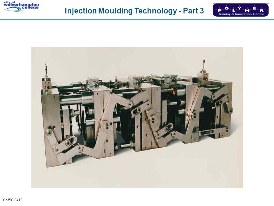
Multi-plate mould tool
3RD DAYLIGHT STIPS SPRUE. EJECTS COMPONENT.

8
Multi-plate mould tool
Advantages Centre gating of multi cavity. Side gating easily achieved. Multi-point gating easily achieved. Automatic de-gating. Disadvantages ASK DELEGATES? Higher cost of tooling. More moving parts. Critical opening stroke. Runner wastage. Stripper plate

9
Question 2 On a mould that incorporates a hot runner, what might soft start facility be used for?

10
Hot runner READ

12
ASK DELEGATES THE FOUR ZONES.
The hot runner Ideally the sprue bush, hot tips and the manifold should have separate controllers and thermocouples. On the example four zones are required. READ. ASK DELEGATES THE FOUR ZONES.

13
READ. DISADVANTAGE. ADVANTAGE. DESCRIBE.
Hot runner systems The 2 plate tool Increases the mould height. Saved material waste from the sprue & runner. READ. DISADVANTAGE. ADVANTAGE. DESCRIBE. Material delivered to the cavities in the same condition as the melt left the barrel.

14
Question 3 Please list 3 advantages and 3 limitations when using hot runner moulds?

15
Limitations of a hot runner
Increased set-up times. Warm up period required. Increased tooling costs. Manifold leaks. Higher maintenance costs. Degradation with certain polymers. Heat expansion problems. READ. SOFT START! CARTRIDGE HEATERS ABSORB MOISTURE AS THEY COOL.

16
When a hot runner leaks ….it leaks !

17
Advantages of a hot runner
No feed system to be removed. Reduced mould open stroke. Reduced shot weight. Injection time reduced. Automatic de-gating. Easier to balance gates. Increased number of cavities possible. ASK DELEGATES. READ.

18
When using hot runner moulds
Avoid regrind to avoid blocked nozzles. Avoid heat sensitive polymers. Do not flick off cold slugs. Keep systems fully maintained. READ.

19
Question 4 What is the primary function of a stack mould?

20
Stack mould - reduced projected area
Braun Ireland DESCRIBE. WHY DO WE USE. TO REDUCE PROJECTED AREA. WEVE SEEN AIR EJECTION CAN YOU NAME ANY OTHERS.

22
Valve to Valve

23
Spring opening

24
Question 5 What are the different types of ejector pins and methods of ejection?

25
Combination round/blade ejection
Blade ejectors DESCRIBE WHY WE USE. USE PROPS. Round ejectors

26
USED TO PRODUCE CORE IN MOULDING.
Sleeve ejection Core pin Sleeve DESCRIBE. USE PROPS. USED TO PRODUCE CORE IN MOULDING.

27
PIN STAYS STILL SLEEVE COMES FORWARD.
Sleeve ejection Good even ejection around bosses but quite expensive. PIN STAYS STILL SLEEVE COMES FORWARD.

28
Stripper plate ejection
Stripper block ASK DELEGATES. DISADVANTAGE. CAN’T SHORT SHOT. ADVANTAGE. LEAVES NO WITNESS MARKS.

29
USED USUALLY WITH STIPPER PLATES ON DEEP DRAWN COMPONENTS.
Air ejection DESCRIBE. USED USUALLY WITH STIPPER PLATES ON DEEP DRAWN COMPONENTS. BUCKETS, BOWLS, BINS. Air off - spring returns valve to its rear position

30
Question 6 When would mechanical or hydraulic core movement be used?

31
Mechanical core pin movement
READ

32
HYDRAULIC CYLINDERS CAN MOVE CORES.
Core pulling HYDRAULIC CYLINDERS CAN MOVE CORES. MORE EXPENSIVE.

33
Core movement by hydraulics
Points to remember: Machines will need to be programmed. There are many different sequences. Must know the sequence, before opening or closing the mould. READ. WRITE ON BOARD COMMON CORE SEQUENCES. TOOLS ARE EXPENSIVE. IF TIME. GO TO BALCONY. BREAK 3.10. If in doubt ASK!

34
Question 7 When designing a mould, utilising a cold runner system, what are the primary considerations to be addressed?

35
NAME PARTS. SPRUE, RUNNER, GATE.
The feed system NAME PARTS. SPRUE, RUNNER, GATE.

36
COLD POINTS. MISS MATCH. MODIFIED TRAPIZOIDAL.
Runner shape Which shape will give the best flow? 10 deg COLD POINTS. MISS MATCH. MODIFIED TRAPIZOIDAL.

37
IS THIS A GOOD RUNNER LAYOUT?
EXPLAIN WHY.

38
Runner layout

39
General guidelines Single Mould
As the number of cavities increases, so must the machine tonnage 2,4,6,8,12,16,24,32,48,64 cavities are typical. No odd numbers!

40
Question 8 Please list advantages & disadvantages for the selected gates:
Sprue gate Pin gate Diaphragm gate Tab gate Flash gate Fan gate Tunnel gate

41
ADVANTAGES / DISADVANTAGES. SPRUE =GOOD FILL-LARGE WITNESS
Gates Sprue gate Diaphragm gate Pin gate Flash gate Fan gate Tab gate ASK DELEGATES. ADVANTAGES / DISADVANTAGES. SPRUE =GOOD FILL-LARGE WITNESS PIN =NO WITNESS+SHORT FREEZE OFF TIME. DIAPHRAGM =EVEN FILL-NEEDS SECOND OP. TAB =ABS-JETTING

42
Submarine/tunnel gate
Sprue Runner Component ASK DELEGATES. WHY DO WE USE? Gate

43
Submarine/tunnel gate
SELF DEGATING. NO WITNESS MARKS.

44
SIZE SMALLER. FEED FREEZE OFF.
Gate considerations Size in relation to section thickness of the moulding. Always feed into the thickest section. Position gate to give even filling. SIZE SMALLER. FEED FREEZE OFF.

45
Question 9 Why is mould venting required?

46
ASK DELEGATES. Mould venting To prevent burning/dieseling.
Exhaust grooves Vent depth 0.025mm To prevent burning/dieseling. ASK DELEGATES.

47
Question 10 What are the general considerations for the correct moulding temperature?

48
Mould temperature control
High enough to allow filling of the mould, without premature freezing of the polymer melt. As uniform as possible, to ensure the mould is cooled equally in all areas. Mould temperature has the greatest influence on part quality. READ.

49
Piping up considerations
ASK DELEGATES CORRECT WAY TO PIPE UP. 1in 2in 1out 2out

50
Cool core pin technology
Coolant flow Used as an alternative to cooling channels. BERILIUM. MOULDMAX. USED WERE CHANNELS CANT BE PUT. Core

51
Beryllium copper insert to improve cooling
READ

52
Cooling baffles Baffles may be offset to achieve turbulent flow.
Must be piped correctly.

53
Spiral flow cooling out in out in Material entering the mould
will be at its hottest in out in

54
Machine Practical 1

55
Injection Moulding Technology Mould Design & Construction
Part 3 Mould Design & Construction READ

56
Injection Moulding Technology
Part 3 Plastics Materials

57
Aim To provide an understanding of plastics materials technology and processing behaviour when injection moulded.

58
Objectives By the end of the session you will be able to:
Describe, in simple terms, the molecular structure of plastics materials. State three methods of classifying plastics, giving examples. Describe the MFI test and it’s relevance. Identify five common additives to modern plastics.

59
What are plastics? Synthetic - Man made Organic - Based on carbon
Polymers - Describes the MOLECULES of polymers Many units To show that polymers are based on oil by-products hence when PP degrades or is over heated it returns to an oil like substance

60
Polymerisation example
H H c H c H c H c H H Example ETHYLENE Monomer

61
Polymerisation example
Catalyst - heat, pressure and time c H H c c Heat and pressure in side reaction vessel Initiator starts reaction Monomer units start to link together Reaction continues in a random manner but must be controlled Terminator added to stop reaction giviong polymer chains of similar length – Molecular weight distribution ETHYLENE monomer POLYETHYLENE polymer

62
Polymer examples Propylene monomer Polypropylene polymer Styrene
Polystyrene polymer Vinyl Chloride monomer Polyvinylchloride polymer Sequence first monomer to polymer for PP and PS Next two start with Polymer to monomer – get delegates to think what monomer you start with. Polycarbonate – this is to demo that not all polymers follow the same route. In the case of polycarbonate: Produced by polycondesnation from Bisphenol A – this is manufactured by mixing phenol, acetone and phosgene Phosgene Bis-Phenol Acetone monomer Polycarbonate polymer

63
Summary Polymer chains have a coiled spring like structure.
Picture shows the chain in reality – not just a line drawing it’s a 3D structure Demo spring like structure of polymer in real terms Discuss length of chains, size of atoms, behaviour in mould – spring stretches during injection relaxes, recoils as it cools hence shrinkage About 5,000 times longer than their diameter. Chains are upwards of 1,000,000 repeat units long. Processing of polymers reduces the chain length and hence the loss of properties when using regrind.

64
Curing/solidification Cross-linking reaction
Classifying plastics Thermosets Example - Bakelite Flows due to pressure Heat Melt Curing/solidification Heat & Pressure Cross-linking reaction Thermoset materials Warm barrel 100 to 150, hot tool 150 to 200 Soften polymer so it will flow, force into mould, under pressure and heat chemical reaction occurs Cross-links – chicken wire effect – can not be reversed Some thermosets such as expoy resin require a catalyste to start reaction e.g Araldite two part epoxy resin, mix the two elements reaction occurs cross links are formed

65
Classifying plastics Thermosetting Bakelite Rubber Epoxy Melamine
Polyester (Chemical change - Boiled egg) PET (Polyester) in both lists since it is possible eto have both a Thermoset PET – car body repair kits and a thermoplastic PET for bottles.
 PET (Polyester) in both lists since it is possible eto have both a Thermoset PET – car body repair kits and a thermoplastic PET for bottles.")
66
Example - Polyethylene
Classifying plastics Thermoplastics Example - Polyethylene Melt Flows under pressure Heat Cool/remove heat Solidification PET (Polyester) in both lists since it is possible eto have both a Thermoset PET – car body repair kits and a thermoplastic PET for bottles. Thermmoplastics – hot barrel / cooler tool Some interaction or bonds between chains such as Van der Waals forces, entanglement, structure but can be reversed when heat applied
 in both lists since it is possible eto have both a Thermoset PET – car body repair kits and a thermoplastic PET for bottles. Thermmoplastics – hot barrel / cooler tool. Some interaction or bonds between chains such as Van der Waals forces, entanglement, structure but can be reversed when heat applied.")
67
Classifying plastics Thermoplastics Polyethylene Polystyrene
Polycarbonate Nylon Polyester (Physical change - Ice to water) PET (Polyester) in both lists since it is possible to have both a thermoset PET – car body repair kits and a thermoplastic PET for bottles. Discuss Thermopastic Elastomers – rubber type properties but can be processed on a thermoplastic machine, structural difference gives rise to hard and soft domains – Two shot machine
 PET (Polyester) in both lists since it is possible to have both a thermoset PET – car body repair kits and a thermoplastic PET for bottles. Discuss Thermopastic Elastomers – rubber type properties but can be processed on a thermoplastic machine, structural difference gives rise to hard and soft domains – Two shot machine.")
68
Classifying plastics Commodity Engineering

69
Prices are only approximate
Classifying plastics Commodity Price/tonne Plastic Polypropylene HDPE LDPE Polystyrene SAN Acrylic ABS £600 - £950 £500 - £900 £600 - £900 £600 - £1200 £900 - £1500 £ £2500 Commodity plastics High volume parts Disposable goods / packaging industry Service properties low Low strength / heat resistance / chemical resistance etc. High volume production of polymer hence low cost Prices are only approximate

70
Classifying plastics Engineering Plastic Price/tonne
PET Acetal (POM) Nylon (PA) PBT PC PAI PEEK £ £1200 £ £1900 £ £2400 £ £2700 £ £3500 £ £40000 £ £69000 Engineering materials will have much better mechcanical properties such as tensile strength, a high strength to weight ratio, good chemical resistance and much more expensive PEEK - £4,500 per tonne Manifold PA66 GF35 Prices are only approximate.
 Nylon (PA) PBT. PC. PAI. PEEK. £ £1200. £ £1900. £ £2400. £ £2700. £ £3500. £ £ £ £ Engineering materials will have much better mechcanical properties such as tensile strength, a high strength to weight ratio, good chemical resistance and much more expensive. PEEK - £4,500 per tonne. Manifold PA66 GF35. Prices are only approximate.")
71
Amorphous versus Semi-crystalline! What are the differences?
Classifying plastics Amorphous versus Semi-crystalline! What are the differences? Engineering materials will have much better mechcanical properties such as tensile strength, a high strength to weight ratio, good chemical resistance and much more expensive PEEK - £4,500 per tonne

72
Structural changes of polymers
Molten state Flow COOL Amorphous Random structure Semi-Crystalline Ordered structure

73
Classifying plastics Thermoplastics Amorphous Semi-crystalline
Polycarbonate A.B.S. Polystyrene S.A.N. Acrylic Polyethylene Polypropylene Nylon Acetal Polyester Introduce concept of amorphous and semi-crystalline sub-divisions of thermoplastics

74
Why is crystallinity important?
Property differences Why is crystallinity important? Amorphous Semi-crystalline Generally clear Generally opaque High mould Shrinkage 1.5%-2.5% Low mould shrinkage 0.5% Wide melting range Narrow melting range

75
+ Flow behaviour Semi-crystalline Ease Amorphous of flow Temperature
Amorphous plastics Melt and solidify over a WIDE temperature range. (PA) + Ease of flow Temperature Amorphous Semi-crystalline plastics Melt and solidify over a NARROW temperature range. (i.e they have a crystalline melting point) (PMMA)
 + Ease. of. flow. Temperature. Amorphous. Semi-crystalline plastics. Melt and solidify over a. NARROW temperature. range. (i.e they have a crystalline melting point) (PMMA)")
76
Examples: HDPE, PA, POM, PVC, PS, PP.
Homo-polymers The homo-polymer chains comprise of the same repeat unit for their entire length. Examples: HDPE, PA, POM, PVC, PS, PP.

77
Co-polymers Co-polymer chains comprise of two or more different repeat units, which are linked together. Examples: ABS, SAN, POM, PP, HIPS. (ABS – Acrylonitrile-Butadiene-Styrene) Mention Co-polymers can be symmetrical, random or branched use white baord to illustartae Ratio of component polymers changed to give different properties I.e ABS increase Butadiene to give greater impact strength, increase Acrylonitrile for chemical resistance this leads to a range of grades of ABS being available fro the supplier.
 Mention Co-polymers can be symmetrical, random or branched use white baord to illustartae. Ratio of component polymers changed to give different properties I.e ABS increase Butadiene to give greater impact strength, increase Acrylonitrile for chemical resistance this leads to a range of grades of ABS being available fro the supplier.")
78
High Impact Polystyrene
Blends & Alloys Blends Two or more different polymers in the same matrix but not linked. Noryl PPO/PS HIPS High Impact Polystyrene Alloys Two or more different polymers in the same matrix plus a chemically adhesive additive. Xenoy Bayblend PC/PBT PC/ABS

79
Additives in polymers Why use additives?
Modify service performance. Modify processing performance.

80
Types of additives Assist processing Heat stabilisers Lubricants
Essential additives Modify bulk mechanical properties Plasticisers Reinforcing fillers Toughening agents = Flexible PVC Reduce costs??? Powdered fillers e.g. talc or chalk

81
Additional additives Modify surface properties Anti-static agents
Modify optical properties Pigments and dyes Prevent ageing U.V. stabiliser Others Blowing agents Flame retardants

82
Melt Flow Index apparatus (MFI)
")
83
Melt Flow Index apparatus
Weight Thermometer inside an oil filled well Barrel Insulation Polymer Melt Avg. weight of extruded plastic in 10 mins. Die

84
Effects of processing Chain length First pass Lower viscosity
Higher MFI Lower strength material Chain lengths can be shortened by processing or regrinding.

85
Melt Flow Index Summary The bigger the value - the easier the flow.
Values can reflect relative chain lengths. Low shear (not representative of injection moulding) Spiral flow test better. Used as a quality control for incoming material. Specific test conditions must be used.
 Spiral flow test better. Used as a quality control for incoming material. Specific test conditions must be used.")
86
Common trade names Trade names Family names Cycolac, Lustran, Terluran
ABS Delrin, Hostaform, Kematal Acetal (POM) Plexiglas, Lucite (Perspex) Acrylic (PMMA) Lupolen, Rigidex, Vestolen HDPE Make reference to grades e.g.: Nylon 6 / 66 Styron, Lacqrene HIPS Ultramid A, Zytel 66, Maranyl A Nylon 66 (PA 66) Santoprene, EPDM TPE’s
 Plexiglas, Lucite (Perspex) Acrylic (PMMA) Lupolen, Rigidex, Vestolen. HDPE. Make reference to grades e.g.: Nylon 6 / 66. Styron, Lacqrene. HIPS. Ultramid A, Zytel 66, Maranyl A. Nylon 66 (PA 66) Santoprene, EPDM. TPE’s.")
87
Pre-treatment of plastics
Moisture absorption - Hygroscopic POM, PE, PP, PS, PVC Not affected - drying not usually required. PMMA, ABS, SAN, PP + talc Water absorbed - may need drying. Do not forget to mention that certain additives may require drying I.e. Talc fillers Use coaster from dupont one moulded dry condition and one moulded without drying Dry part – tough / strong Wet part – visual no diffenerce, will break very easily SAFE – MUST WEAR GLOVES TO DO DEMO POTENTIAL FOR INJURY Last class all polymers in this list are oxidised or attacked by moisture if processed in damp condition this damages the chain and therefore the mechcanical properties PC is the same PC, PET, PA, PBT, PUR Damaged by water - needs drying.

88
Pre-treatment of plastics
Methods for removing moisture: Vacuum oven Dehumidifying dryer Do not forget to mention that certain additives may require drying I.e. Talc fillers

89
Pre-treatment of plastics
Key drying considerations: Type of material – ABS, PC, PA plus virgin or regrind. Temperature and time required. Volume held in dryer to give correct throughput. Maintenance of dryer. Do not forget to mention that certain additives may require drying I.e. Talc fillers

90
Injection Moulding Technology
Part 3 Plastics Materials

91
Injection Moulding Technology Processing & Troubleshooting
Part 3 Processing & Troubleshooting

92
Processing

93
Aims during the injection phase
Start Mould Safety Apply Locking Tonnage Open Period Mould Closes Injection Speed & Pressure Mould Opens Injection Phase Mould 99% Full Holding Phase Cooling Phase

94
Mould fill analysis

95
Melt flow behaviour Frozen layers Mould cavity Fountain flow

96
Example of skin formation
Previous colour New colour Skin Real example of skin forming and demos that the material flows threw the centre then out to the sides Parts produced when production changed from yellow to black colored parts Yellow material enters cavity first and is pushed out to the surface and forms the skin, the black material follows in behind and forms the core. Principle applied in some two shot process’s where internal layer is a regrind or second polymer.

97
Molecular orientation
Slow injection speed Mould cavity Low orientation/Stiff flow Thicker frozen layers

98
Molecular orientation
Fast Injection Speed Mould cavity High orientation/Easy flow Thinner frozen layers

99
Slower filling or colder moulds
Residual stress Slower filling or colder moulds Thick frozen layers Mould cavity High residual stress !

100
Faster filling or hotter moulds
Residual stress Faster filling or hotter moulds Thin frozen layers Mould cavity Low residual stress !

101
Effect of residual stress
Fast fill rate - Lower internal stress Slow fill rate - Higher internal stress Two moulding with different internal stress’s due to the rate of fill of the cavity Both parts made from same machine in the same material with all conditions the same accept for the injection speed One injected at 99% speed the other at 10% speed Both then placed in an oven at 100C for 24 hours – stress is then allowed to relax as the material heats up hence the distortion Which has the highest stress levels ? Why ?

102
Injection phase Summary Aim to fill the mould as quickly as possible.
Uniform melt front speed as part fills. Mould cavities fill evenly. Ensure mould is 99% full.

103
Aims during the holding phase
Start Mould Safety Apply Locking Tonnage Mould Closes Open Period Injection Speed & Pressure Injection Phase Mould Opens Mould 99% Full Hold Pressure & Time Holding Phase Cooling Phase Gate Freeze-off

104
Polymer compression Pressure is applied to the melt.
Melt density increases. Material shrinkage reduces.

105
Gate freeze-off 2 4 6 8 10 12 14 16 (gms) Gate frozen Weight
using 55oC mould & 230oC melt Gate frozen using 35oC mould & 230oC melt Weight Holding time (secs)
")
106
Holding phase Summary Ensure adequate compression of the melt.
Reduce sinks and voids by compensating for the shrinkage of the polymer chains Obtain consistent component quality by establishing gate freeze-off time. Obtain correct component weight/dimensions by the application of a suitable pressure. Rule of thumb: Amorphous plastics require a low holding pressure. Semi-crystalline plastics require a high holding pressure.

107
Aims of the cooling phase
Start Mould Safety Apply Locking Tonnage Open Period Mould Closes Injection Speed & Pressure Mould Opens Injection Phase Mould 99% Full Screw Back Completed Holding Phase Hold Pressure & Time Cooling Phase Gate Freeze-off Start Screw Rotation

108
Factors to consider Polymer type – Semi-crystalline or Amorphous.
HDT – Heat Distortion Temperature. Capacity of temperature control unit. Cooling time versus refill time (open nozzle).
.")
109
Cooling rate, shrinkage & distortion
Mould Tool ? HOT SIDE COLD SIDE Which way will the part bend ?

110
Cooling rate, shrinkage & distortion
Residual orientation effect (stress) Normal shrinkage effect Hot side Cold side Hot side Cold side More shrinkage Low orientation High orientation Aimated to show the two effects Distortion at the moulding machine Warpage as part relaxes in service or storage
 Normal shrinkage effect. Hot side. Cold side. Hot side. Cold side. More. shrinkage. Low orientation. High orientation. Aimated to show the two effects. Distortion at the moulding machine. Warpage as part relaxes in service or storage.")
111
Cooling phase Summary To remove heat at an appropriate rate to promote maximum service properties. To remove the heat from all cavities evenly. To allow the part to be ejected without distortion. To provide sufficient time to plasticise a homogeneous mass of molten polymer.

112
Troubleshooting

113
Troubleshooting Is the fault acceptable – check the first off.
ASSESSMENT Is the fault acceptable – check the first off. CORRECTION If not, then check the basics first: The mould (damage, vents). The material (grade, batch, moisture). The machine (wear, malfunction).
. The material (grade, batch, moisture). The machine (wear, malfunction).")
114
Slower filling or colder moulds
Residual stress Slower filling or colder moulds Thick frozen layers Mould cavity High residual stress !

115
Faster filling or hotter moulds
Residual stress Faster filling or hotter moulds Thin frozen layers Mould cavity Low residual stress !

116
Relationship between faults & cycle steps
OUT OF CYCLE COOLING HOLDING INJECTION Flash Short Gas trap Jetting Flow lines Weld lines Dieseling Weight Sinking Flash Voids Dimensions Distortion Contamination Mica marks Illustartion to show where faults occur within cycle Get delegates to say where examples such as flash,weld lines etc. occur then show lists Note: Some faults can be related to more than one specific part of the injection moulding cycle.

117
Examine the mouldings and determine the:
Troubleshooting Examine the mouldings and determine the: Fault Cause Remedy Issue samples – get delegates to consider fault – Cause - Remedy

118
Example of Fault - Cause - Remedy
Burn mark (Dieseling) Trapped gas Clean vents. Reduce Locking tonnage. Reduce injection speeds or profile. Example to show Fault – definintion of problem ( Flash – excess material arouond edge of part ) Cause – why flash occurs Remedy – how to cure, note multiple remedies, need to determine appropiate steps Reduce melt temperatures.
 Trapped. gas. Clean vents. Reduce Locking tonnage. Reduce injection. speeds or profile. Example to show. Fault – definintion of problem ( Flash – excess material arouond edge of part ) Cause – why flash occurs. Remedy – how to cure, note multiple remedies, need to determine appropiate steps. Reduce melt temperatures.")
119
Processing variables Short term Long term Locking tonnage
Holding pressure time Cooling time Injection speed Holding pressure Change over position Shot weight Decompression Ejector speed Melt temperature Mould temperature (Oil temperature) Determine actual temperatures using a pyrometer for both mould and melt. Short term vs long term Back pressure Screw speed
 Determine actual. temperatures using. a pyrometer for. both mould and melt. Short term vs long term. Back pressure. Screw speed.")
120
Systematic approach Eliminate faults in order of priority:
Those that potentially damage the mould - Flash - Gas burns/traps Optimise the filling phase % full Order in which problems addressed Filling phase faults - Jetting - Flow lines - Weld lines

121
Systematic approach Holding phase related - Voids - Sinks - Undersized
Optimise the holding phase - Holding pressure - Gate freeze-off time - Cushion Size Order in which problems addressed Optimise the cycle time - Cooling time

122
Troubleshooting Summary
Adopt a logical and systematic approach Change one condition at a time Consider the interaction of conditions Keep samples Keep notes Be patient Don’t be a knob Twiddler!!

123
Injection Moulding Technology Processing & Troubleshooting
Part 3 Processing & Troubleshooting

124
Blade ejection READ

125
Round ejection READ

126
Sleeve ejection READ Return

127
Sprue bush READ Return

Similar presentations