Download presentation
Presentation is loading. Please wait.

1
University College of Medical Sciences & GTB Hospital, Delhi
Physiology of positive pressure ventilation & newer modes of ventilation Dr. Megha Aggarwal University College of Medical Sciences & GTB Hospital, Delhi

2
Mechanical ventilation – supports / replaces the normal ventilatory pump moving air in & out of the lungs. Primary indications – apnea Ac. ventilation failure Impending ventilation failure Severe oxygenation failure

3
Goals Manipulate gas exchange
↑ lung vol – FRC, end insp / exp lung inflation Manipulate work of breathing (WOB) Minimize CVS effects
 Minimize CVS effects.")
4
Negative pressure ventilation Positive pressure ventilation
ARTIFICIAL VENTILATION Negative pressure ventilation - Creates a transairway P gradient by ↓ alveolar P to a level below airway opening P - Creates – P around thorax e.g. iron lung chest cuirass / shell Positive pressure ventilation - Achieved by applying + P at airway opening producing a transairway P gradient

5
Noninvasive ventilation without artificial airway Nasal , face mask
adv. Avoid intubation / c/c Preserve natural airway defences Comfort Speech/ swallowing + Less sedation needed Intermittent use Disadv Cooperation Mask discomfort Air leaks Facial ulcers, eye irritation, dry nose Aerophagia Limited P support e.g. BiPAP, CPAP

6
Ventilatory support FULL PARTIAL All energy provided by ventilator
e.g. ACV / full support SIMV ( RR = & TV = 8-10 ml/kg) Pt provides a portion of energy needed for effective ventilation e.g. SIMV (RR < 10) Used for weaning WOB total = WOB ventilator (forces gas into lungs)+ WOB patient (msls draw gas into lungs)
 Pt provides a portion of energy needed for effective ventilation. e.g. SIMV (RR < 10) Used for weaning. WOB total = WOB ventilator (forces gas into lungs)+ WOB patient (msls draw gas into lungs)")
7
Understanding physiology of PPV
Different P gradients Time constant Airway P ( peak, plateau, mean ) PEEP and Auto PEEP Types of waveforms
 PEEP and Auto PEEP. Types of waveforms.")
8
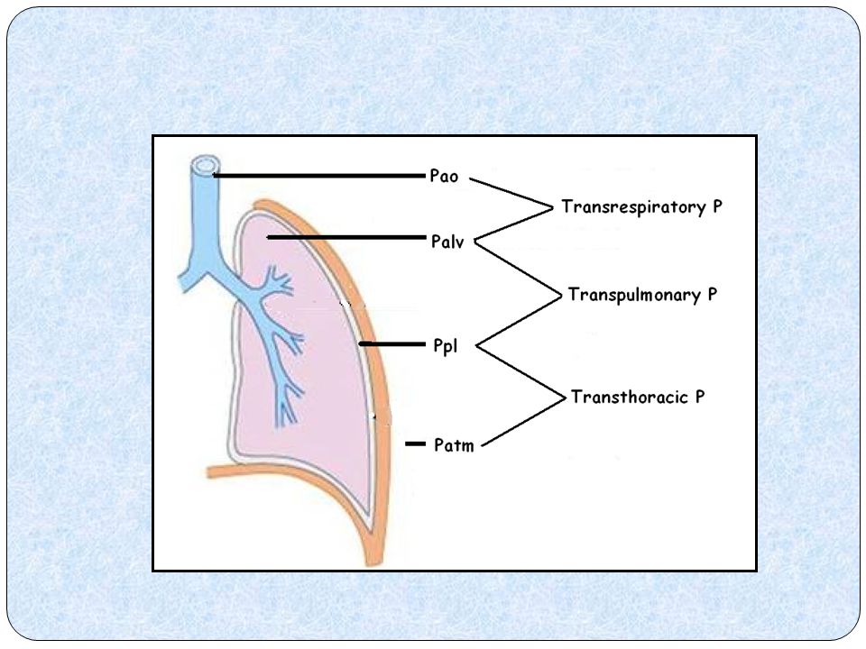
Pressure gradients

10
Distending pressure of lungs
Resistance load Distending pressure Flow through the airways is generated by Transairway pressure (pressure at the airway opening minus pressure in the lungs). Expansion of the elastic chamber is generated by Transthoracic pressure (pressure in the lungs minus pressure on the body surface). Transrespiratory pressure (pressure at the airway opening minus pressure on the body surface) is the sum of these two pressures and is the total pressure required to generate inspiration. Transrespiratory pressure can have two components, one secondary to the ventilator (pvent) and one secondary to the respiratory muscles (Pmusc) Trans pulmonary pressure (pressure at airway opening minus pleural pressure) [= Transrespiratory pressure?] Transpulmonary pressure is the distending force of the lung The airway-pressure gauge on a positive-pressure ventilator displays transrespiratory pressure Pressure, volume, and flow are functions of time and are called variables. They are all measured relative to their values at end expiration. Elastance and resistance are assumed to remain constant and are called parameters.– PPMV 2nd edition 2006 Elastance(measure of stiffness) is the inverse of compliance(measure of stretchiness), and an increase in elastance implies that the system is becoming stiffer. Mean airway pressure Paw = Transrespiratory pressure Mean alveolar pressure Palv = Transthoracic pressure ?transpulmonary pressure is the distending pressure in a spontaneously(negative) breathing patient and transrespiratory pressure is the distending pressure in positive pressure ventilation Elastance load 10
. Expansion of the elastic chamber is generated by Transthoracic pressure (pressure in the lungs minus pressure on the body surface). Transrespiratory pressure (pressure at the airway opening minus pressure on the body surface) is the sum of these two pressures and is the total pressure required to generate inspiration. Transrespiratory pressure can have two components, one secondary to the ventilator (pvent) and one secondary to the respiratory muscles (Pmusc) Trans pulmonary pressure (pressure at airway opening minus pleural pressure) [= Transrespiratory pressure ] Transpulmonary pressure is the distending force of the lung. The airway-pressure gauge on a positive-pressure ventilator displays transrespiratory pressure. Pressure, volume, and flow are functions of time and are called variables. They are all measured relative to their values at end expiration. Elastance and resistance are assumed to remain constant and are called parameters.– PPMV 2nd edition Elastance(measure of stiffness) is the inverse of compliance(measure of stretchiness), and an increase in elastance implies that the system is becoming stiffer. Mean airway pressure Paw = Transrespiratory pressure. Mean alveolar pressure Palv = Transthoracic pressure. transpulmonary pressure is the distending pressure in a spontaneously(negative) breathing patient and transrespiratory pressure is the distending pressure in positive pressure ventilation. Elastance load. 10.")
11
Airway pressures Peak insp P (PIP) Highest P produced during insp.
PRESISTANCE + P INFLATE ALVEOLI Dynamic compliance Barotrauma Plateau P Observed during end insp pause P INFLATE ALVEOLI Static compliance Effect of flow resistance negated

12
Time constant Defined for variables that undergo exponential decay
Time for passive inflation / deflation of lung / unit t = compliance X resistance = VT peak exp flow Normal lung C = 0.1 L/cm H2O R = 1cm H2O/L/s COAD – resistance to exp increases → time constant increases → exp time to be increased lest incomplete exp ( auto PEEP generates). ARDS - inhomogenous time constants
. ARDS - inhomogenous time constants.")
13
Why and how to separate dynamic & static components ?
Why – to find cause for altered airway pressures How – adding end insp pause - no airflow, lung expanded, no expiration

14
How -End inspiratory hold
End-inspiratory pause Pendelluft phenomenon Visco-elastic properties of lung At the start of inflation, the airway pressure immediately rises because of the resistance to gas flow (A), and at the end of inspiratory gas flow the airway pressure immediately falls by the same pressure (A) to an inflexion point. Thereafter, the airway pressure more gradually declines to the plateau pressure. The loss of airway pressure after the inflexion (B) is due to gas redistribution (Pendelluft) and and the visco-plasto-elastic lung and thorax behaviour P2(Pplat) is the static pressure of the respiratory system, which in the absence of flow equals the alveolar pressure, which reflects the elastic retraction of the entire respiratory system. The pressure drop from PIP to P1 represents the pressure required to move the inspiratory flow along the airways without alveolar interference, thus representing the pressure dissipated by the flow-dependent resistances(airway resistance). The slow post-occlusion decay from P1 to P2 depends on the viscoelastic properties of the system and on the pendulum-like movement of the air (pendelluft). During the post-inspiratory occlusion period there is a dynamic elastic rearrangement of lung volume, which allows the different pressures in alveoli at different time constants to equalize, and depends on the inhomogeneity of the lung parenchyma. The lung regions that have a low time constant (ie, rapid zones), where the alveolar pressure rises rapidly, are emptied in the lung regions that have higher time constants (ie, slow zones), where the pressure rises more slowly because of higher resistance or lower compliance The static compliance of the respiratory system mirrors the elastic features of the respiratory system, whereas the dynamic compliance also includes the resistive (flow-dependent) component of the airways and the endotracheal tube When the inspiratory pause is shorter than 2 seconds, P2 does not always reflect the alveolar pressure. The compliance value thus measured is called quasi-static compliance. In healthy subjects the difference between static compliance and quasi-static compliance is minimal, whereas it is markedly higher in patients who have acute respiratory distress syndrome or chronic obstructive pulmonary disease - Lucangelo U; Respir Care 2005;50(1):55–65 Ppeak < 50 cm H2O; Pplat < 35 cm H2O – to avoid barotrauma – ACCP concensus conference – Slutsky AS – Chest 1993 Ppeak < 50 cm H2O Pplat < 30 cm H2O Ppeak = Pplat + Paw
, and at the end of inspiratory gas flow the airway pressure immediately falls by the same pressure (A) to an inflexion point. Thereafter, the airway pressure more gradually declines to the plateau pressure. The loss of airway pressure after the inflexion (B) is due to gas redistribution (Pendelluft) and and the visco-plasto-elastic lung and thorax behaviour. P2(Pplat) is the static pressure of the respiratory system, which in the absence of flow equals the alveolar pressure, which reflects the elastic retraction of the entire respiratory system. The pressure drop from PIP to P1 represents the pressure required to move the inspiratory flow along the airways without alveolar interference, thus representing the pressure dissipated by the flow-dependent resistances(airway resistance). The slow post-occlusion decay from P1 to P2 depends on the viscoelastic properties of the system and on the pendulum-like movement of the air (pendelluft). During the post-inspiratory occlusion period there is a dynamic elastic rearrangement of lung volume, which allows the different pressures in alveoli at different time constants to equalize, and depends on the inhomogeneity of the lung parenchyma. The lung regions that have a low time constant (ie, rapid zones), where the alveolar pressure rises rapidly, are emptied in the lung regions that have higher time constants (ie, slow zones), where the pressure rises more slowly because of higher resistance or lower compliance. The static compliance of the respiratory system mirrors the elastic features of the respiratory system, whereas the dynamic compliance also includes the resistive (flow-dependent) component of the airways and the endotracheal tube. When the inspiratory pause is shorter than 2 seconds, P2 does not always reflect the alveolar pressure. The compliance value thus measured is called quasi-static compliance. In healthy subjects the difference between static compliance and quasi-static compliance is minimal, whereas it is markedly higher in patients who have acute respiratory distress syndrome or chronic obstructive pulmonary disease - Lucangelo U; Respir Care 2005;50(1):55–65. Ppeak < 50 cm H2O; Pplat < 35 cm H2O – to avoid barotrauma – ACCP concensus conference – Slutsky AS – Chest Ppeak < 50 cm H2O. Pplat < 30 cm H2O. Ppeak = Pplat + Paw.")
15
Pendulum like movement of air between lung units
Reflects inhomogeneity of lung units More in ARDS and COPD Can lead to falsely measured high Pplat if the end-inspiratory occlusion duration is not long enough

16
Why

17
Mean airway P (MAP) average P across total cycle time (TCT)
MAP = 0.5(PIP-PEEP)X Ti/TCT + PEEP Decreases as spontaneous breaths increase MAPSIMV < MAP ACV Hemodynamic consequences Factors Mandatory breath modes ↑insp time , ↓ exp time ↑ PEEP ↑ Resistance, ↓compliance Insp flow pattern
X Ti/TCT + PEEP. Decreases as spontaneous breaths increase. MAPSIMV < MAP ACV. Hemodynamic consequences. Factors. Mandatory breath modes. ↑insp time , ↓ exp time. ↑ PEEP. ↑ Resistance, ↓compliance. Insp flow pattern.")
18
PEEP BENEFITS Restore FRC/ Alveolar recruitment ↓ shunt fraction
PEEP prevents complete collapse of the alveoli and keep them partially inflated and thus provide protection against the development of shear forces during mechanical inflation BENEFITS Restore FRC/ Alveolar recruitment ↓ shunt fraction ↑Lung compliance ↓WOB ↑PaO2 for given FiO2 DETRIMENTAL EFFECTS Barotrauma ↓ VR/ CO ↑ WOB (if overdistention) ↑ PVR ↑ MAP ↓ Renal / portal bld flow
 ↑ PVR. ↑ MAP. ↓ Renal / portal bld flow.")
19
How much PEEP to apply? Lower inflection point – transition from flat to steep part - ↑compliance - recruitment begins (pt. above closing vol) Upper inflection point – transition from steep to flat part - ↓compliance - over distension
 Upper inflection point – transition from steep to flat part - ↓compliance - over distension")
20
Set PEEP above LIP – Prevent end expiratory airway collapse
Set TV so that total P < UIP – prevent overdistention Limitation – lung is inhomogenous - LIP / UIP differ for different lung units

21
Auto-PEEP or Intrinsic PEEP
What is Auto-PEEP? Normally, at end expiration, the lung volume is equal to the FRC When PEEPi occurs, the lung volume at end expiration is greater then the FRC

22
Auto-PEEP or Intrinsic PEEP
Function of- Ventilator settings – TV, Exp time Lung func – resistance, compliance Why does hyperinflation occur? Airflow limitation because of dynamic collapse No time to expire all the lung volume (high RR or Vt) Lesions that increase expiratory resistance
 Lesions that increase expiratory resistance.")
23
Auto-PEEP or Intrinsic PEEP
Auto-PEEP is measured in a relaxed pt with an end- expiratory hold maneuver on a mechanical ventilator immediately before the onset of the next breath

24
Inadequate expiratory time - Air trapping
Flow curve FV loop iPEEP In most patients with obstructive lung disease, failure to reach zero flow at the end of a relaxed expiration signifies that lung volume is above functional residual capacity and indicates dynamic hyperinflation High inspiratory flow allow short inspiratory time and therefore longer expiratory time for any given respiratory rate . Volume control ventilation is better than pressure control for COAD patients Allow more time for expiration Increase inspiratory flow rate Provide ePEEP

25
Disadv Barotrauma / volutrauma ↑WOB a) lung overstretching ↓contractility of diaphragm b) alters effective trigger sensitivity as autoPEEP must be overcome before P falls enough to trigger breath ↑ MAP – CVS side effects May ↑ PVR Minimising Auto PEEP ↓airflow res – secretion management, bronchodilation, large ETT ↓Insp time ( ↑insp flow, sq flow waveform, low TV) ↑ exp time (low resp rate ) Apply PEEP to balance AutoPEEP
 lung overstretching ↓contractility of diaphragm b) alters effective trigger sensitivity as autoPEEP must be overcome before P falls enough to trigger breath. ↑ MAP – CVS side effects. May ↑ PVR. Minimising Auto PEEP. ↓airflow res – secretion management, bronchodilation, large ETT. ↓Insp time ( ↑insp flow, sq flow waveform, low TV) ↑ exp time (low resp rate ) Apply PEEP to balance AutoPEEP.")
26
Cardiovascular effects of PPV
Spontaneous ventilation PPV

27
Determinants of hemodynamic effects due to – change in ITP, lung volumes, pericardial P severity – lung compliance, chest wall compliance, rate & type of ventilation, airway resistance

28
Low lung compliance – more P spent in lung expansion & less change in ITP
less hemodynamic effects (DAMPNING EFFECT OF LUNG) Low chest wall compliance – higher change in ITP needed for effective ventilation more hemodynamic effects
 Low chest wall compliance – higher change in ITP needed for effective ventilation. more hemodynamic effects.")
29
Effect on CO ( preload , afterload )
Decreased PRELOAD compression of intrathoracic veins (↓ CVP, RA filling P) Increased PVR due to compression by alveolar vol (decreased RV preload) Interventricular dependence - ↑ RV vol pushes septum to left & ↓ LV vol & LV output Decreased afterload 1. emptying of thoracic aorta during insp 2. Compression of heart by + P during systole 3. ↓ transmural P across LV during systole
 Increased PVR due to compression by alveolar vol (decreased RV preload) Interventricular dependence - ↑ RV vol pushes septum to left & ↓ LV vol & LV output. Decreased afterload. 1. emptying of thoracic aorta during insp. 2. Compression of heart by + P during systole. 3. ↓ transmural P across LV during systole.")
30
↓ preload, ventricular filling ↓ afterload , ↑ventricular emptying
PPV ↓ preload, ventricular filling ↓ afterload , ↑ventricular emptying CO – INCREASE DECREASE Intravascular fluid status Compensation – HR, vasoconstriction Sepsis, PEEP, MAP LV function

31
Effect on other body systems

32
Presenter – Megha Aggarwal Moderator – Dr Sujata Chaudhary
Physiology of positive pressure ventilation & newer modes of ventilation Presenter – Megha Aggarwal Moderator – Dr Sujata Chaudhary Dr Asha Tyagi

33
Overview Mode of ventilation – definition Breath – characteristics
Breath types Waveforms – pressure- time, volume –time, flow-time Modes - Volume & pressure limited Conventional modes of ventilation Newer modes of ventilation

34
What is a ‘ mode of ventilation’ ?
A ventilator mode is delivery a sequence of breath types & timing of breath

35
Breath characteristics
A= what initiates a breath - TRIGGER B = what controls / limits it – LIMIT C= What ends a breath - CYCLING

36
TRIGGER What the ventilator senses to initiate a breath
Patient Pressure Flow Machine Time based Recently – EMG monitoring of phrenic Nerve via esophageal transducer Pressure triggering -1 to -3 cm H2O Flow triggering -1 to -3 L/min

37
CONTROL/ LIMIT Variable not allowed to rise above a preset value
Pressure Controlled Pressure targeted, pressure limited - Ppeak set Volume Variable Volume Controlled Volume targeted, volume limited - VT set Pressure Variable Dual Controlled volume targeted (guaranteed) and pressure limited Variable not allowed to rise above a preset value Does not terminate a breath Pressure Volume
 and pressure limited. Variable not allowed to rise above a preset value. Does not terminate a breath. Pressure. Volume.")
38
CYCLING VARIABLE Determines the end of inspiration and the switch to expiration Machine cycling Time Pressure Volume Patient cycling Flow May be multiple but activated in hierarchy as per preset algorithm

39
Breath types Control/Mandatory Machine triggered and machine cycled
Assisted Patient triggered but machine cycled Spontaneous Both triggered and cycled by the patient

40
Waveforms Volume -time Flow - time Pressure - time

41
a) Volume – time graphs Air leaks Calibrate flow transducers
 Volume – time graphs Air leaks Calibrate flow transducers")
42
b) Flow waveforms 1. Inspiratory flow waveforms
 Flow waveforms 1. Inspiratory flow waveforms")
43
Sine Resembles normal inspiration More physiological Square Maintains constant flow high flow with ↓ Ti & improved I:E Square- volume limited modes Decelerating – pressure limited modes Flow slows down as alveolar pressure increases meets high initial flow demand in spont breathing patient - ↓WOB Decelerating The parameter that is manipulated to drive inflation is known as the ‘control’ parameter, while the parameter that is measured to provide feedback to limit or augment the control parameter is described as the ‘target’ or ‘limit’ parameter Produces highest PIP as airflow is highest towards end of inflation when alveoli are less compliant Accelerating Not used

44
Inspiratory and expiratory flow waveforms

45
2. Expiratory flow waveform
Expiratory flow is not driven by ventilator and is passive Is negative by convention Similar in all modes Determined by Airway resistance & exp time (Te) Use 1.Airtrapping & generation of AutoPEEP 2.Exp flow resistance (↓PEFR + short Te) & response bronchodilators (↑PEFR)
 Use. 1.Airtrapping & generation of AutoPEEP. 2.Exp flow resistance (↓PEFR + short Te) & response bronchodilators (↑PEFR)")
46
c) Pressure waveform Spontaneous/ mandatory breaths
Patient ventilator synchrony Calculation of compliance & resistance Work done against elastic and resistive forces AutoPEEP ( by adding end exp pause)
")
47
Classification of modes of ventilation
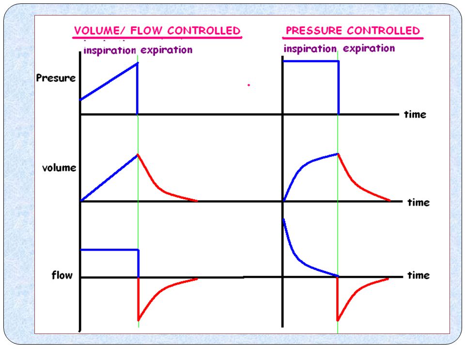
Volume controlled Pressure controlled TV & inspiratory flow are preset Airway P is preset Airway P depends on above & lung elastance & compliance TV & insp flow depend on above & lung elastance & compliance

49
Volume controlled Pressure controlled
Trigger patient / machine Patient / machine Limit Flow Pressure Cycle Volume / time time / flow TV Constant variable Peak P Variable constant Modes ACV, SIMV PCV, PSV

50
Volume controlled Pressure controlled
Advantages Guaranteed TV Less atelectasis TV increases linearly with MV Limits excessive airway P ↑ MAP by constant insp P – better oxygenation Better gas distribution – high insp flow ↓Ti & ↑Te ,thereby, preventing airtrapping Lower WOB – high initial flow rates meet high initial flow demands Lower PIP – as flow rates higher when lung compliance high i.e early insp. phase Disadvantages Limited flow may not meet patients desired insp flow rate- flow hunger May cause high Paw ( barotrauma) Variable TV ↑TV as compliance ↑ ↓TV as resistance ↑
 Variable TV. ↑TV as compliance ↑ ↓TV as resistance ↑")
51
Conventional modes of ventilation
Control mandatory ventilation (CMV / VCV) Assist Control Mandatory Ventilation (ACMV) Intermittent mandatory ventilation (IMV) Synchronized Intermittent Mandatory Ventilation (SIMV) Pressure controlled ventilation (PCV) Pressure support ventilation (PSV) Continuous positive airway pressure (CPAP)
 Assist Control Mandatory Ventilation (ACMV) Intermittent mandatory ventilation (IMV) Synchronized Intermittent Mandatory Ventilation (SIMV) Pressure controlled ventilation (PCV) Pressure support ventilation (PSV) Continuous positive airway pressure (CPAP)")
52
1. Control mandatory ventilation (CMV / VCV)
Breath - MANDATORY Trigger – TIME Limit - VOLUME Cycle – VOL / TIME Patient has no control over respiration Requires sedation and paralysis of patient

53
2. Assist Control Mandatory Ventilation (ACMV)
Breath – MANDATORY ASSISTED Trigger – PATIENT TIME Limit - VOLUME Cycle – VOLUME / TIME Once patient initiates the breath the ventilator takes over the WOB If he fails to initiate, then the ventilator does the entire WOB Patient has partial control over his respiration – Better Pt ventilator synchrony Ventilator rate determined by patient or backup rate (whichever is higher) – risk of respiratory alkalosis if tachypnoea PASSIVE Pt – acts like CMV ACTIVE pt – ALL spontaneous breaths assisted to preset volume
 – risk of respiratory alkalosis if tachypnoea. PASSIVE Pt – acts like CMV. ACTIVE pt – ALL spontaneous breaths assisted to preset volume.")
54
3. Intermittent mandatory ventilation (IMV)
Breath – MANDATORY SPONTANEOUS Trigger – PATIENT VENTILATOR Limit - VOLUME Cycle - VOLUME Basically CMV which allows spontaneous breaths in between Disadvantage In tachypnea can lead to breath stacking - leading to dynamic hyperinflation Not used now – has been replaced by SIMV Breath stacking Spontaneous breath immediately after a controlled breath without allowing time for expiration ( SUPERIMPOSED BREATHS)
")
55
4.Synchronized Intermittent Mandatory Ventilation (SIMV)
Breath – SPONTANEOUS ASSISTED MANDATORY Trigger – PATIENT TIME Limit - VOLUME Cycle – VOLUME/ TIME

56
Basically, ACMV with spontaneous breaths (which may be pressure supported) allowed in between
Synchronisation window – Time interval from the previous mandatory breath to just prior to the next time triggering, during which ventilator is responsive to patients spontaneous inspiratory effort Weaning Adv Allows patients to exercise their respiratory muscles in between – avoids atrophy Avoids breath stacking – ‘Synchronisation window’

57
5.Pressure controlled ventilation (PCV)
Breath – MANDATORY Trigger – TIME Limit - PRESSURE Cycle – TIME/ FLOW Rise time Time taken for airway pressure to rise from baseline to maximum

58
6.Pressure support ventilation (PSV)
Breath – SPONTANEOUS Trigger – PATIENT Limit - PRESSURE Cycle – FLOW ( 5-25% OF PIFR) After the trigger, ventilator generates a flow sufficient to raise and then maintain airway pressure at a preset level for the duration of the patient’s spontaneous respiratory effort
 After the trigger, ventilator generates a flow sufficient to raise and then maintain airway pressure at a preset level for the duration of the patient’s spontaneous respiratory effort.")
59
7.Continuous positive airway pressure (CPAP)
Breath – SPONTANEOUS CPAP is actually PEEP applied to spontaneously breathing patients. But CPAP is described a mode of ventilation without additional inspiratory support while PEEP is not regarded as a stand-alone mode

60
Newer modes of ventilation
Volume assured pressure support (VAPS) Volume support (VS) Pressure regulated volume controlled (PRVC) Automode Automatic Tube Compensation (ATC) Airway pressure release ventilation (APRV) Proportional Assist Ventilation (PAV) Biphasic positive airway pressure (BiPAP) Neurally Adjusted Ventilatory Assist (NAVA)
 Volume support (VS) Pressure regulated volume controlled (PRVC) Automode. Automatic Tube Compensation (ATC) Airway pressure release ventilation (APRV) Proportional Assist Ventilation (PAV) Biphasic positive airway pressure (BiPAP) Neurally Adjusted Ventilatory Assist (NAVA)")
61
Newer modes of ventilation
Recent modes allow ventilators to control one variable or the other based on a feedback loop Volume controlled Has the desired/ set TV been delivered ? Is the Airway P exceeding set P limit ? Feedback loop Pressure controlled

62
Dual modes of ventilation
Devised to overcome the limitations of both V & P controlled modes Dual control within a breath Switches from P to V control during the same breath e.g. VAPS PA Dual control from breath to breath P limit ↑ or ↓ to maintain a clinician set TV ANALOGOUS to a resp therapist who ↑ or ↓ P limit of each breath based on TV delivered in last breath

63
Dual control within a breath
Combined adv – High & variable initial flow rate of P controlled breath ( thereby - ↑ pt – vent synchrony, ↓WOB, ↓sense of breathlessness) Assured TV & MV as in V controlled breaths Starts as P limited breaths but change over to V limited breath by converting decelerating flow to constant flow if minimum preset TV not delivered
 Assured TV & MV as in V controlled breaths. Starts as P limited breaths but change over to V limited breath by converting decelerating flow to constant flow if minimum preset TV not delivered.")
64
Breath triggered (pt/ time) –
P support level reached quickly – ventilator compares delivered and desired/ set TV Delivered = set TV Breath is FLOW cycled as in P controlled modes Delivered < set TV Changeover from P to V limited ( flow kept constant + Ti ↑) P rises above set P support level till set TV delivered
 P rises above set P support level. till set TV delivered.")
65
Dual control – breath to breath
P limited + FLOW cycled Vol support / variable P support P limited + TIME cycled PRVC

66
↑ - P support ↓ ↓ - P support ↑
Volume support Allows automatic weaning of P support as compliance alters. OPERATION – Preset & constant changes during weaning & guides P support level C = V P P support dependent on C compliance ↑ - P support ↓ ↓ - P support ↑ By 3 cm H2O / breath Deliver desired TV

67
Limitations – MV is fixed , pt may be stuck at that level of support even if pt demand exceeds MV chosen by clinician If tachypnoea occurs – ventilator senses it as ↑ MV and ↓ses P support which is exactly OPPOSITE of what is required

68
Pressure regulated volume controlled (PRVC)
Autoflow / variable P control Similar to VS except that it is a modification of PCV rather than PSV

69
Had it been Conventional V controlled mode – very high P would have resulted in an attempt to deliver set TV BAROTRAUMA Conventional P controlled mode – inadequate TV would have been delivered

70
Automode Shifts between P support (flow cycled)& P control (time cycled) mode with pt efforts Combines VS & PRVC If no efforts : PRVC (time cycled) As spontaneous breathing begins : VS (flow cycled) Pitfalls : During the switch from time-cycled to flow cycled ventilation ↓ Mean airway pressure ↓ hypoxemia may occur
 As spontaneous breathing begins : VS (flow cycled) Pitfalls : During the switch from time-cycled to flow cycled ventilation. ↓ Mean airway pressure ↓ hypoxemia may occur.")
71
Automatic Tube Compensation
Compensates for the resistance of ETT Facilitates “ electronic weaning “ i.e pt during ATC mimic their breathing pattern as if extubated ( provided upper airway contorl provided) Operation As the flow ↑ / ETT dia ↓, the P support needs to be ↑to ↓WOB ∆P (P support) α (L / r4 ) α flow α WOB
 Operation. As the flow ↑ / ETT dia ↓, the P support needs to be ↑to ↓WOB. ∆P (P support) α (L / r4 ) α flow α WOB.")
72
Under/ overcompensation may result.
Static condition – single P support level can eliminate ETT resistance Dynamic condition – variable flow e.g. tachypnoea & in different phases of resp. - P support needs to be continously altered to eliminate dynamically changing WOB d/t ETT Feed resistive coef of ETT Feed % compensation desired Measures instantaneous flow Calculates P support proportional to resistance throughout respiratory cycle Limitation – resistive coef changes in vivo ( kinks, temp molding, secretions) Under/ overcompensation may result.
 Under/ overcompensation may result.")
73
Airway pressure release ventilation (APRV)
High level of CPAP with brief intermittent releases to a lower level Conventional modes – begin at low P & elevate P to accomplish TV APRV – commences at elevated P & releases P to accomplish TV

74
Higher plateau P – improves oxygenation
Release phase – alveolar ventilation & removal of CO2 Active patient – spontaneous breathing at both P levels Passive patient – complete ventilation by P release

75
Settings 1. Phigh (15 – 30 cmH2O ) 2. Plow (3-10 cmH2O ) == PEEP 3
Settings 1.Phigh (15 – 30 cmH2O ) 2.Plow (3-10 cmH2O ) == PEEP 3. F = 8-15 / min 4. Thigh /Tlow = 8:1 to 10:1 If ↑ PaCO2 -↑ Phigh or ↓ Plow - ↑ f If ↓ PaO2 - ↑ Plow or FiO2
 2.Plow (3-10 cmH2O ) == PEEP 3. F = 8-15 / min 4. Thigh /Tlow = 8:1 to 10:1 If ↑ PaCO2 -↑ Phigh or ↓ Plow - ↑ f If ↓ PaO2 - ↑ Plow or FiO2")
76
Advantages Preservation of spontaneous breathing and comfort with most spontaneous breathing occurring at high CPAP breathing occurring at high CPAP ↓WOB ↓Barotrauma ↓Circulatory compromise Better V/Q matching

77
Proportional Assist Ventilation
Targets fixed portion of patient’s work during “spontaneous” breaths Automatically adjusts flow, volume and pressure needed each breath

78
Ventilator measures – elastance & resistance
WOB Ventilator measures – elastance & resistance Clinician sets -“Vol. assist %” reduces work of elastance “Flow assist%” reduces work of resistance's Increased patient effort (WOB) causes increased applied pressure (and flow & volume) ELASTANCE (TV) RESISTANCE (Flow)
 causes increased applied pressure (and flow & volume) ELASTANCE. (TV) RESISTANCE. (Flow)")
79
Limitations 1. Elastance (E) & resistance (R) cannot be measured accurately. 2. E & R vary frequently esp in ICU patients. 3. Curves to measure E ( P-V curve) & R (P-F curve ) are not linear as assumed by ventilator.
 & R (P-F curve ) are not linear as assumed by ventilator.")
80
Biphasic positive airway pressure (BiPAP)
PCV & a variant of APRV Time cycled alteration between 2 levels of CPAP BiPAP – P support for spontaneous level only at low CPAP level Bi-vent - P support for spontaneous level at both low & high CPAP Spontaneous breathing at both levels Changeover between 2 levels of CPAP synchronized with exp & insp

81
. Can provide total / partial ventilatory support BiPAP – PCV – if pt not breathing BiPAP – SIMV- spontaneous breathing at lower CPAP + mandatory breaths by switching between 2 CPAP levels CPAP – both CPAP levels are identical in spontaneously breathing patient BiPAP – P support – additional P support at lower CPAP Bi- vent – additional P support at both levels of CPAP

82
BiPAP Bi- vent

83
Advantages Allows unrestricted spontaneous breathing Continuous weaning without need to change ventilatory mode – universal ventilatory mode Synchronization with pt’s breathing from exp. to insp. P level & vice versa Less sedation needed

84
Neurally Adjusted Ventilatory Assist (NAVA)
Electrical activity of respiratory muscles used as input Eadi (electrical activity of diaphragm) Cycling on, cycling off: determined by Eadi Synchrony between neural & mechanical inspiratory time is guaranteed Patient comfort
 Cycling on, cycling off: determined by Eadi. Synchrony between neural & mechanical inspiratory time is guaranteed. Patient comfort.")
85
References Egan’s – fundamentals of respiratory care 9th ed. International Anaesthesiology Clinics – Update on respiratory critical care , vol 37, no 3, 1999. Anaesthesia newsletter ,Indore city ,June 2009, vol 10, no 2 David W Chang, Clinical application of mechanical ventilation 2nd ed Wylie and Churchill Davidson – A Practice of Anesthesia, 5th ed. Paul L Marino, The ICU Book, 3rd ed.

Similar presentations