Download presentation
Presentation is loading. Please wait.

1
Lecture 23 Filters Hung-yi Lee

2
Filter Types wco : cutoff frequency Bandwidth B = wu - wl
Lowpass filter Highpass filter Notch filter Bandpass filter

3
Real World Ideal filter

4
Transfer Function – Rules
Filter is characterized by its transfer function The poles should be at the left half of the s-plane. We only consider stable filter. Given a complex pole or zero, its complex conjugate is also pole or zero.

5
Transfer Function – Rules
Filter is characterized by its transfer function As the frequency increase, the output will become infinity. :improper filter Remember the two rules :proper filter We only consider proper filer. The filters consider have more poles than zeros.

6
Filter Order Order = n The order of the denominator is the order of the filter. order=1 order=4

7
Outline Textbook: Chapter 11.2 Second-order Filter First-order Filters
Lowpass Filter Highpass Filter Lowpass Filter Highpass Filter Bandpss Filter Notch Filter

8
First-order Filters

9
Firsr-order Filters Case 1: Case 2: zero or first order 0 or 1 zero
1 pole Case 1: 1 pole, 0 zero Case 2: 1 pole, 1 zero

10
Firsr-order Filters - Case 1
Lowpass filter As ω increases Magnitude decrease Phase decrease Pole p is on the negative real axis

11
Firsr-order Filters - Case 1
Amplitude of the transfer function of the first-order low pass filter Ideal Lowpass filter First-order Lowpass filter

12
Firsr-order Filters - Case 1
Find cut-off frequency ωco of the first-order low pass filter Lowpass filter At DC Find cut-off frequency ωco such that

13
Firsr-order Filters - Case 2
Case 2-1: Absolute value of zero is smaller than pole Magnitude is proportional to the length of green line divided by the length of the blue line Zero can be positive or negative Low frequency ≈ |z|/|p| Because |z|<|p| The low frequency signal will be attenuated If z=0, the low frequency can be completely block Not a low pass

14
Firsr-order Filters - Case 2
Case 2-1: Absolute value of zero is smaller than pole Magnitude is proportional to the length of green line divided by the length of the blue line High frequency The high frequency signal will pass High pass If z=0 (completely block low frequency)
")
15
First-order Filters - Case 2
Find cut-off frequency ωco of the first-order high pass filter (the same as low pass filter)
")
16
First-order Filters - Case 2
Case 2-2: Absolute value of zero is larger than pole Low frequency ≈ |z|/|p| Because |z|>|p| The low frequency signal will be enhanced. High frequency: magnitude is 1 The high frequency signal will pass. Neither high pass nor low pass

17
First-order Filters Consider vin as input (pole) If vl is output
Reasonable from intuition If vl is output Lowpass filter If vh is output Highpass filter (pole)
")
18
First-order Filters (pole)
")
19
Cascading Two Lowpass Filters

20
Cascading Two Lowpass Filters

21
Cascading Two Lowpass Filters
The first low pass filter is influenced by the second low pass filter!

22
Cascading Two Lowpass Filters

23
Cascading Two Lowpass Filters

24
Second-order Filters

25
Second-order Filter Case 1: No zeros Must having two poles Case 2:
0, 1 or 2 zeros Second order 2 poles Case 1: No zeros Must having two poles Case 2: One zeros Case 3: Two zeros

26
Second-order Filter – Case 1

27
Second-order Filter – Case 1
Real Poles The magnitude is As ω increases The magnitude monotonically decreases. Decrease faster than first order low pass

28
Second-order Filter – Case 1
Complex Poles The magnitude is As ω increases, l1 decrease first and then increase. l2 always increase What will happen to magnitude? 1. Increase 2. Decrease 3. Increase, then decrease 4. Decrease, then increase

29
Second-order Filter – Case 1
Complex Poles If ω > ωd l1 and l2 both increase. The magnitude must decrease. What will happen to magnitude? 1. Increase 2. Decrease 3. Increase, then decrease 4. Decrease, then increase

30
Second-order Filter – Case 1
Complex Poles When ω < ωd Maximize the magnitude Minimize

31
Second-order Filter – Case 1
Minimize Minimize (maximize)
")
32
Second-order Filter – Case 1
Lead to maximum The maxima exists when Peaking No Peaking Peaking

33
Second-order Filter – Case 1
Lead to maximum The maxima exists when Peaking Assume

34
Second-order Filter – Case 1
For complex poles

35
Second-order Filter – Case 1
Q times Not the peak value Q times of DC gain

36
Second-order Filter – Case 1
Lead to maximum For complex poles

37
Second-order Filter – Case 1
Lead to maximum Lead to maximum Bad number …… The maximum value is The maximum exist when

38
Second-order Filter – Case 1
Real Poles Case 1-2 Complex Poles (No Peaking) Which one is considered as closer to ideal low pass filter?
 Which one is considered as closer to ideal low pass filter")
39
Complex poles Peaking (Butterworth filter)
")
40
Butterworth – Cut-off Frequency
ω0 is the cut-off frequency for the second-order lowpass butterworth filter (Go to the next lecture first)
")
41
Second-order Filter – Case 2
Case 2: 2 poles and 1 zero Case 2-1: 2 real poles and 1 zero

42
Second-order Filter – Case 2
Case 2: 2 poles and 1 zero Case 2-1: 2 real poles and 1 zero flat Plat 辮子 Bandpass Filter

43
Second-order Filter – Case 2
Case 2-2: 2 complex poles and 1 zero Two Complex Poles -40dB + Zero +20dB

44
Second-order Filter – Case 2
Case 2-2: 2 complex poles and 1 zero -40dB -20dB Two Complex Poles -40dB + -20dB +20dB Zero +20dB

45
Second-order Filter – Case 2
Case 2-2: 2 complex poles and 1 zero Two Complex Poles Highly Selective -40dB -20dB +20dB + Zero +20dB Bandpass Filter

46
Bandpass Filter Bandpass filter: 2 poles and zero at original point
Find the frequency for the maximum amplitude bandpass filter ω0?

47
Bandpass Filter Find the frequency for the maximum amplitude

48
Bandpass Filter Find the frequency for the maximum amplitude
is maximized when (Center frequency) The maximum value is K’. (Bandpass filter)
 The maximum value is K’. (Bandpass filter)")
49
Bandpass Filter is maximized when The maximum value is K’.
Bandwidth B = ωr - ωl

50
Bandpass Filter - Bandwidth B
Four answers? Pick the two positive ones as ωl or ωr

51
Bandpass Filter - Bandwidth B
Q measure the narrowness of the pass band Q is called quality factor

52
Bandpass Filter Usually require a specific bandwidth
The value of Q determines the bandwidth. When Q is small, the transition would not be sharp.

53
Stagger-tuned Bandpass Filter

54
Stagger-tuned Bandpass Filter - Exercise 11.64
Center frequency: 10Hz Bandpass Filter Center frequency: 40Hz We want flat passband. Tune the value of Q to achieve that

55
Stagger-tuned Bandpass Filter - Exercise 11.64
Test Different Q Q=3 Q=1 Q=0.5

56
Second-order Filter – Case 3
Case 3: Two poles, Two zeros Case 3-1: Two real zeros Two Complex poles Two real poles High-pass

57
Second-order Filter – Case 3
Case 3: Two poles, Two zeros Case 3-2: Two Complex zeros Fix ω0 Larger Q Larger θ Describe sth. Fix ωβ Larger Q β Larger θ β

58
Second-order Filter – Case 3
Case 3: Two poles, Two zeros Case 3-2: Two Complex zeros Two poles -40dB Describe sth. Two zeros +40dB

59
Second-order Filter – Case 3
Case 3: Two poles, Two zeros Case 3-2: Two Complex zeros High-pass Notch

60
Second-order Filter – Case 3
Case 3: Two poles, Two zeros Case 3-2: Two Complex zeros Two poles -40dB Describe sth. Two zeros +40dB

61
Second-order Filter – Case 3
Case 3: Two poles, Two zeros Case 3-2: Two Complex zeros Describe sth. Low-pass Notch

62
Second-order Filter – Case 3
Case 3: Two poles, Two zeros Case 3-2: Two Complex zeros Large Q Two poles -40dB Describe sth. Two zeros +40dB small Qβ

63
Second-order Filter – Case 3
Case 3: Two poles, Two zeros Case 3-2: Two Complex zeros Describe sth.

64
Second-order Filter – Case 3
Case 3: Two poles, Two zeros Case 3-2: Two Complex zeros small Q Two poles -40dB Describe sth. +40dB Two zeros Larger Qβ

65
Second-order Filter – Case 3
Case 3: Two poles, Two zeros Case 3-2: Two Complex zeros Describe sth. Standard Notch Filter

66
Second-order Filter – Case 3
Case 3: Two poles, Two zeros Case 3-2: Two Complex zeros If the two zeros are on the ω axis The notch filter will completely block the frequency ω0 Describe sth.

67
Notch Filter The extreme value is at ω= ω0 (Notch filter)
")
68
Second-order RLC Filters
B A C D RLC series circuit can implement high-pass, low-pass, band-pass and notch filter.

69
Second-order RLC Filters
B A DC (O) Infinity (X) DC (X) Infinity (O) Low-pass Filter High-pass Filter
 Infinity (X) DC (X) Infinity (O) Low-pass Filter. High-pass Filter.")
70
Second-order RLC Filters
Band-pass Filter

71
Second-order RLC Filters – Band-pass
40pF to 360pF C L=240μH, R=12Ω Frequency range Center frequency: Max: 1.6MHz min: 0.54MHz

72
Second-order RLC Filters – Band-pass
40pF to 360pF C L=240μH, R=12Ω Frequency range 0.54MHz ~ 1.6MHz Q is 68 to 204.

73
Band-pass

74
Band-pass Band-pass Filter

75
Second-order RLC Filters
Notch Filter

76
Active Filter

77
Basic Active Filter -i i

78
First-order Low-pass Filter

79
First-order High-pass Filter

80
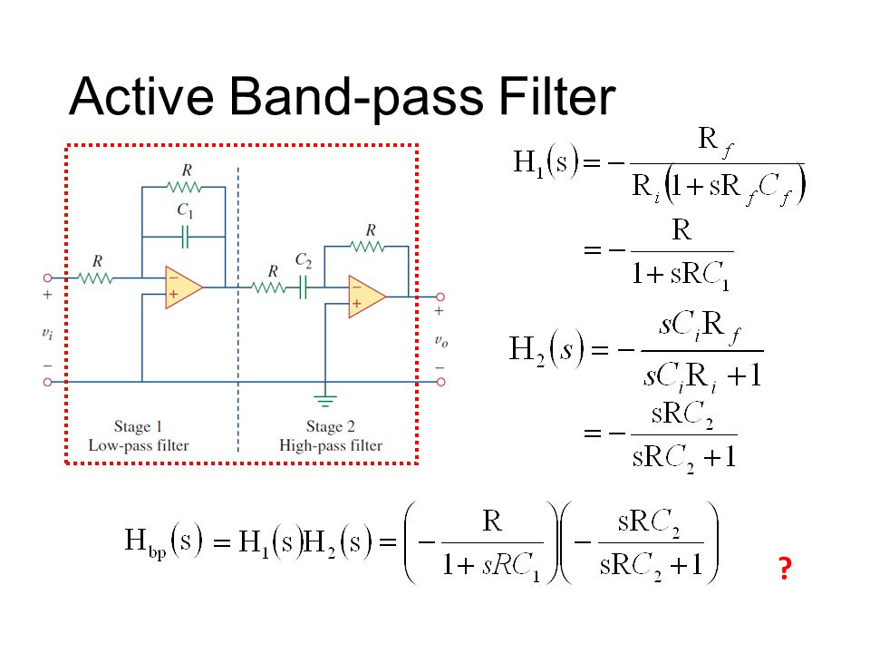
Active Band-pass Filter
Union of low and high

81
Active Band-pass Filter
?
82
Loading The loading Z will change the transfer function of passive filters. The loading Z will NOT change the transfer function of the active filter.

83
The transfer function is H(s).
Cascading Filters If there is no loading The transfer function is H(s). One Filter Stage Model
. One Filter Stage Model.")
84
Overall Transfer Function:
Cascading Filters 1st Filter with transfer function H1(s) 2st Filter with transfer function H2(s) Overall Transfer Function:
 2st Filter with. transfer function H2(s) Overall Transfer Function:")
85
Cascading Filters 1st Filter with transfer function H1(s)
")
86
Cascading Filters 1st Filter with transfer function H1(s)
If zero output impedance (Zo1=0) or If infinite input impedance (Zi2=∞)
 or If infinite input impedance (Zi2=∞)")
87
Cascading Filters – Input & Output Impedance

88
Cascading Filters – Basic Active Filter
If zero output impedance (Zo1=0) or If infinite input impedance (Zi2=∞) Cascading Filters – Basic Active Filter -i =0 i =0 =0
 or If infinite input impedance (Zi2=∞) Cascading Filters – Basic Active Filter. -i. =0. i. =0. =0.")
89
Active Notch Filter A B Which one is correct?

90
Active Notch Filter Low-pass Filter Add Together High-pass Filter
cover High-pass Filter

91
Homework 11.19

92
Thank you!

93
Answer 11.19: Ra=7.96kΩ, Rb= 796Ω, va(t)=8.57cos(0.6ω1t-31。)
vb(t)=0.60cos(0.6ω1t+87。) +7.86cos(1.2ω2t+40。) (ω1 and ω2 are 2πf1 and 2πf2 respectively) 11.22: x=0.14, ωco=0.374/RC 11.26(refer to P494): ω0=2π X 6 X 10^4, B= ω0=2π X 5 X 10^4, Q=1.2, R=45.2Ω, C=70.4nF 11.28(refer to P494): C=0.25μF, Qpar=100, Rpar=4kΩ, R||Rpar=2kΩ, R=4kΩ
=0.60cos(0.6ω1t+87。) +7.86cos(1.2ω2t+40。) (ω1 and ω2 are 2πf1 and 2πf2 respectively) 11.22: x=0.14, ωco=0.374/RC (refer to P494): ω0=2π X 6 X 10^4, B= ω0=2π X 5 X 10^4, Q=1.2, R=45.2Ω, C=70.4nF (refer to P494): C=0.25μF, Qpar=100, Rpar=4kΩ, R||Rpar=2kΩ, R=4kΩ.")
94
Acknowledgement 感謝 江貫榮(b02) 上課時指出投影片的錯誤 感謝 徐瑞陽(b02) 上課時糾正老師板書的錯誤
 上課時指出投影片的錯誤 感謝 徐瑞陽(b02) 上課時糾正老師板書的錯誤")
95
Appendix

96
High frequency becomes low frequency
Aliasing Wrong Interpolation Actual signal Sampling High frequency becomes low frequency

97
Phase filter

98
Type Transfer Function Properties
Table Simple Filter Type Transfer Function Properties Lowpass Highpass Bandpass Notch 98

99
Loudspeaker for home usage with three types of dynamic drivers 1
Loudspeaker for home usage with three types of dynamic drivers 1. Mid-range driver 2. Tweeter 3. Woofers

102
From Wiki Butterworth filter – maximally flat in passband and stopband for the given order Chebyshev filter (Type I) – maximally flat in stopband, sharper cutoff than Butterworth of same order Chebyshev filter (Type II) – maximally flat in passband, sharper cutoff than Butterworth of same order Bessel filter – best pulse response for a given order because it has no group delay ripple Elliptic filter – sharpest cutoff (narrowest transition between pass band and stop band) for the given order Gaussian filter – minimum group delay; gives no overshoot to a step function.
 – maximally flat in stopband, sharper cutoff than Butterworth of same order. Chebyshev filter (Type II) – maximally flat in passband, sharper cutoff than Butterworth of same order. Bessel filter – best pulse response for a given order because it has no group delay ripple. Elliptic filter – sharpest cutoff (narrowest transition between pass band and stop band) for the given order. Gaussian filter – minimum group delay; gives no overshoot to a step function.")
103
Link http://www.ti.com/lsds/ti/analog/webench/weben ch-filters.page
d/#/type

106
Suppose this band-stop filter were to suddenly start acting as a high-pass filter. Identify a single component failure that could cause this problem to occur: If resistor R3 failed open, it would cause this problem. However, this is not the only failure that could cause the same type of problem!

Similar presentations


>")


 Amplitude Ratio Phase Shift Highpass Filter Frequency Response Bode Plot Draw frequency.>")


 They.>")
 Hung-yi Lee. Textbook AC Circuit Analysis as Resistive Circuits Chapter 6.3, Chapter 6.5 (out of the scope) Fourier.>")