Download presentation
Presentation is loading. Please wait.

1
3rd Module Microcontroller

2
How is it different from a Microprocessor ??
General-purpose microprocessor CPU for Computers No RAM, ROM, I/O on CPU chip itself Data Bus CPU General-Purpose Micro-processor Serial COM Port I/O Port RAM ROM Timer Address Bus

3
Then What is a Microcontroller ?
A smaller computer On-chip RAM, ROM, I/O ports... Example:Motorola’s 6811, Intel’s 8051, PIC 16X CPU RAM ROM A single chip Microcontroller Serial COM Port I/O Port Timer

4
Microprocessor vs. Microcontroller
CPU is stand-alone, RAM, ROM, I/O, timer are separate designer can decide on the amount of ROM, RAM and I/O ports. expansive versatility general-purpose Microcontroller CPU, RAM, ROM, I/O and timer are all on a single chip fix amount of on-chip ROM, RAM, I/O ports Highly bit addressable for applications in which cost, power and space are critical single-purpose

5
EVOLUTION Flashback !!!! In the year 1976, Motorola created a Microprocessor chip called 6801 which replaced its brother 6800 with certain add-on chips to make a computer. This paved the way for the new revolution in the history of chip design and gave birth to a new entity called MICROCONTROLLER. The INTEL bagged the credit of producing the first Microcontroller with a CPU and 1K bytes of EPROM, 64 Bytes of RAM an 8-Bit Timer and 27 I/O pins in 1976.

6
Evolution contd… Then followed the most popular controller 8051 in the year 1980 with 4K bytes of ROM,128 Bytes of RAM , a serial port, two 16-bit Timers , and 32 I/O pins. The 8051 family has many additions and improvements over the years . The same INTEL introduced a 16 bit controller 8096 in the year 1982.

7
Later INTEL introduced 80c196 series of 16-bit microcontrollers for mainly industrial applications
Microchip, another company has introduced a microcontroller PIC 16C64 an 8-bit in the year 1985. 32-bit microcontrollers have been developed by IBM and Motorola-MPC 505 is a 32-bit RISC controller of Motorola

8
EVOLUTION Flashback !!!! In the year 1976, Motorola created a Microprocessor chip called 6801 which replaced its brother 6800 with certain add-on chips to make a computer. This paved the way for the new revolution in the history of chip design and gave birth to a new entity called MICROCONTROLLER. The INTEL bagged the credit of producing the first Microcontroller with a CPU and 1K bytes of EPROM, 64 Bytes of RAM an 8-Bit Timer and 27 I/O pins in 1976.

9
Evolution contd… Then followed the most popular controller 8051 in the year 1980 with 4K bytes of ROM,128 Bytes of RAM , a serial port, two 16-bit Timers , and 32 I/O pins. The 8051 family has many additions and improvements over the years and remains a most soughtafter tool for todays circuit designers. The same INTEL introduced a 16 bit controller 8096 in the year 1982

10
Later INTEL introduced 80c196 series of 16-bit microcontrollers for mainly industrial applications
Microchip, another company has introduced a microcontroller PIC 16C64 an 8-bit in the year 1985. 32-bit microcontrollers have been developed by IBM and Motorola-MPC 505 is a 32-bit RISC controller of Motorola

11
ARM Controllers In recent times ARM company (Advanced Risc machines) has developed and introduced 32 bit controllers which are highend application devices,especially communication devices like mobiles , ipods etc..
 has developed and introduced 32 bit controllers which are highend application devices,especially communication devices like mobiles , ipods etc..")
12
MCS-51 “Family” of Microcontollers
Feature ROM NO kB kB kB UV Eprom RAM (Bytes) TIMERS I/O PINS SERIAL PORTS INTERRUPT SOURCES
 TIMERS I/O PINS SERIAL PORTS INTERRUPT SOURCES.")
13
Important Features of 8051 4K bytes ROM 128 bytes RAM
Four 8-bit I/O ports Two 16-bit timers Serial interface 64K external code memory space 64K data memory space

14
“Original” 8051 Microcontroller
Oscillator and timing 4096 Bytes Program Memory (ROM) 128 Bytes Data Memory (RAM) Two 16 Bit Timer/Event Counters Internal data bus 8051 CPU Programmable I/O Programmable Serial Port Full Duplex UART Synchronous Shifter 64 K Byte Bus Expansion Control Program memory – RAM or ROM? Data memory – RAM or ROM? subsystem interrupts External interrupts Parallel ports Address Data Bus I/O pins Control Serial Output Serial Input
 128 Bytes. Data Memory. (RAM) Two 16 Bit Timer/Event Counters. Internal data bus CPU. Programmable I/O. Programmable Serial Port Full Duplex UART Synchronous Shifter. 64 K Byte Bus Expansion Control. Program memory – RAM or ROM Data memory – RAM or ROM subsystem interrupts. External interrupts. Parallel ports. Address Data Bus. I/O pins. Control. Serial Output. Serial Input.")
15
Pin Description of the 8051 The 8051 is a 40 pin device, but out of these 40 pins, 32 are used for I/O. 24 of these are dual purpose, i.e. they can operate as I/O or a control line or as part of address or date bus.

16
8051 CPU Registers A (8-bit Accumulator)
B (8-bit register for Mul &Div) PSW (8-bit Program Status Word) SP (8-bit Stack Pointer) PC (16-bit Program Counter) DPTR (16-bit Data Pointer)
 PSW (8-bit Program Status Word) SP (8-bit Stack Pointer) PC (16-bit Program Counter) DPTR (16-bit Data Pointer)")
17
Special Function Registers
DATA registers CONTROL registers Timers Serial ports Interrupt system Analog to Digital converter Digital to Analog converter etc.. Addresses 80h – FFh Direct Addressing is used to access SFRs

18
List of Registers (*Denotes the SFRs)
")
19
Contd…

20
PSW REGISTER

21
PSW (Program Status Word, Addresses D0h, Bit-Addressable)
The Program Status Word is used to store a number of important bits that are set and cleared by 8051 instructions. The PSW SFR contains the carry flag, the auxiliary carry flag, the overflow flag, and the parity flag. Additionally, the PSW register contains the register bank select flags which are used to select which of the "R" register banks are currently selected.

22
ACC (Accumulator, Addresses E0h, Bit-Addressable)
The Accumulator is one of the most-used SFRs on the 8051 since it is involved in so many instructions. The Accumulator resides as an SFR at E0h, which means the instruction MOV A,#20h is really the same as MOV E0h,#20h. However, it is a good idea to use the first method since it only requires two bytes whereas the second option requires three bytes.

23
B (B Register, Addresses F0h, Bit-Addressable)
The "B" register is used in two instructions: the multiply and divide operations. The B register is also commonly used by programmers as an auxiliary register to temporarily store values.

24
P0 (Port 0, Address 80h, Bit-Addressable)
This is input/output port 0. Each bit of this SFR corresponds to one of the pins on the microcontroller. For example, bit 0 of port 0 is pin P0.0, bit 7 is pin P0.7. Writing a value of 1 to a bit of this SFR will send a high level on the corresponding I/O pin whereas a value of 0 will bring it to a low level.

25
SP (Stack Pointer, Address 81h)
This is the stack pointer of the microcontroller. This SFR indicates where the next value to be taken from the stack will be read from in Internal RAM. If you push a value onto the stack, the value will be written to the address of SP + 1. That is to say, if SP holds the value 07h, a PUSH instruction will push the value onto the stack at address 08h.

26
DPL/DPH (Data Pointer Low/High, Addresses 82h/83h)
The SFRs DPL and DPH work together to represent a 16-bit value called the Data Pointer. The data pointer is used in operations regarding external RAM and some instructions involving code memory. Since it is an unsigned two-byte integer value, it can represent values from 0000h to FFFFh (0 through 65,535 decimal).
.")
27
PCON (Power Control, Addresses 87h)
The Power Control SFR is used to control the 8051's power control modes. Certain operation modes of the 8051 allow the 8051 to go into a type of "sleep" mode which requires much less power. These modes of operation are controlled through PCON. Additionally, one of the bits in PCON is used to double the effective baud rate of the 8051's serial port.

28
TCON (Timer Control, Addresses 88h, Bit-Addressable)
The Timer Control SFR is used to configure and modify the way in which the 8051's two timers operate. This SFR controls whether each of the two timers is running or stopped and contains a flag to indicate that each timer has overflowed.

29
TMOD (Timer Mode, Addresses 89h)
The Timer Mode SFR is used to configure the mode of operation of each of the two timers. Using this SFR your program may configure each timer to be a 16-bit timer, an 8-bit autoreload timer, a 13-bit timer, or two separate timers.

30
TL0/TH0 (Timer 0 Low/High, Addresses 8Ah/8Ch)
These two SFRs, taken together, represent timer 0. Their exact behavior depends on how the timer is configured in the TMOD SFR; however, these timers always count up. What is configurable is how and when they increment in value.

31
SCON (Serial Control, Addresses 98h, Bit-Addressable)
The Serial Control SFR is used to configure the behavior of the 8051's on-board serial port. This SFR controls the baud rate of the serial port, whether the serial port is activated to receive data, and also contains flags that are set when a byte is successfully sent or received.

32
SBUF (Serial Control, Addresses 99h)
The Serial Buffer SFR is used to send and receive data via the on-board serial port. Any value written to SBUF will be sent out the serial port's TXD pin. Likewise, any value which the 8051 receives via the serial port's RXD pin will be delivered to the user program via SBUF. In other words, SBUF serves as the output port when written to and as an input port when read from.

33
IE (Interrupt Enable, Addresses A8h)
The Interrupt Enable SFR is used to enable and disable specific interrupts. The low 7 bits of the SFR are used to enable/disable the specific interrupts, where as the highest bit is used to enable or disable ALL interrupts. Thus, if the high bit of IE is 0 all interrupts are disabled regardless of whether an individual interrupt is enabled by setting a lower bit.

34
IP (Interrupt Priority, Addresses B8h, Bit-Addressable)
The Interrupt Priority SFR is used to specify the relative priority of each interrupt. On the 8051, an interrupt may either be of low (0) priority or high (1) priority. An interrupt may only interrupt interrupts of lower priority. For example, if we configure the 8051 so that all interrupts are of low priority except the serial interrupt, the serial interrupt will always be able to interrupt the system, even if another interrupt is currently executing.
 priority or high (1) priority. An interrupt may only interrupt interrupts of lower priority. For example, if we configure the 8051 so that all interrupts are of low priority except the serial interrupt, the serial interrupt will always be able to interrupt the system, even if another interrupt is currently executing.")
35
Addressing modes Immediate Addressing Direct Addressing
MOV A,#20h Direct Addressing MOV A,30h Indirect Addressing MOV External Direct Addressing MOVX External Indirect Addressing MOVC

36
Immediate Addressing MOV A,#20h
This instruction uses Immediate Addressing because the Accumulator will be loaded with the value that immediately follows; in this case 20 (hexidecimal). Immediate addressing is very fast since the value to be loaded is included in the instruction. However, since the value to be loaded is fixed at compile-time it is not very flexible.
. Immediate addressing is very fast since the value to be loaded is included in the instruction. However, since the value to be loaded is fixed at compile-time it is not very flexible.")
37
Direct Addressing Direct addressing is so-named because the value to be stored in memory is obtained by directly retrieving it from another memory location. For example: MOV A,30h This instruction will read the data out of Internal RAM address 30 (hexadecimal) and store it in the Accumulator.
 and store it in the Accumulator.")
38
Indirect Addressing MOV A,@R0
This instruction causes the 8051 to analyze the value of the R0 register. The 8051 will then load the accumulator with the value from Internal RAM which is found at the address indicated by R0. For example, let’s say R0 holds the value 40h and Internal RAM address 40h holds the value 67h. When the above instruction is executed the 8051 will check the value of R0. Since R0 holds 40h the 8051 will get the value out of Internal RAM address 40h (which holds 67h) and store it in the Accumulator. Thus, the Accumulator ends up holding 67h.
 and store it in the Accumulator. Thus, the Accumulator ends up holding 67h.")
39
External Direct Addressing
MOVX As you can see, both commands utilize DPTR. In these instructions, DPTR must first be loaded with the address of external memory that you wish to read or write. Once DPTR holds the correct external memory address, the first command will move the contents of that external memory address into the Accumulator. The second command will do the opposite: it will allow you to write the value of the Accumulator to the external memory address pointed to by DPTR.

40
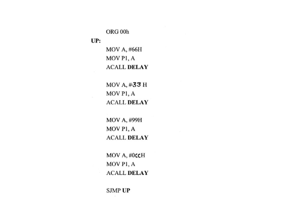
Instruction set Arithmetic instructions JUMP LOOP CALL instructions
Time delay generations

44
Interfacing - sensors

45
LM 35 – Analog Sensor Celsius Sensor (10millivolts/Kelvin) MAX – 6576 – Digital Sensor
 MAX – 6576 – Digital Sensor")
46
Interfacing - keyboard
Keypads are a part of HMI or Human Machine Interface and play really important role in a small embedded system where human interaction or human input is needed. Martix keypads are well known for their simple architecture and ease of interfacing with any microcontroller.

47
Constuction of a keypad is really simple
Constuction of a keypad is really simple. As per the outline shown in the figure below we have four rows and four columns. In between each overlapping row and column line there is a key.

48
Matrix Keypad

49
Interfacing with 8051

Similar presentations


 are all contained in a single package.>")
