Download presentation
Presentation is loading. Please wait.

1
Session 1 Creepage and Clearance Test
CTL WORKSHOP 2008 Session 1 Creepage and Clearance Test

2
Tasks and aims for today
Get to know someone that you have never had a conversation with before Discuss with them how you use proficiency testing programs within your laboratory. (This will be “summed up” at the end of the day – so pay attention!!!)
")
3
What is this a picture of?
Flowers?, YELLOW flowers?, Daffodils?, Country scene?, garden?, a backyard? All people will take something different from a picture. Similarly, people approach adherence to a standard in slightly different ways, simply because they see different things in it.

4
Think about what you , your management and/or your NCB could, or would, request from a PTP that is not already provided, which would enhance the benefits you could get from proficiency testing programs. Apart from non-conformance reports for your own lab, is there anything you would rather not get from a PT program? These questions are posed to keep in mind, as we will be dealing with these later in the day.

5
Creepage and Clearance Testing
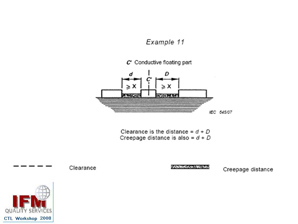
What is the definition of clearance? What is the definition of creepage distances? Clearance: distance through air between live parts Creepage: distance along a surface between live parts

6
The Background (that almost everyone in this community knows…..)
Most laboratories measure Clearance distances well. For creepage distances, the variation with which the distance is measured increases with the number and type of features of the sample. The more complex the sample, the more variation in the result. Certain geometry of sample results in varied application of the rules

7
Previous programs Every proficiency testing program has one or more “design challenge(s)” – meaning a particular aspect of the test is focused upon. 01e6 – first challenge - find the shortest path from the top of the board to a feature on the bottom of the board. 01e6 – second challenge – remember that clearance distances cannot be longer than creepage distances

8
Outcomes of 01e6 Very few labs found the shortest path from the top feature to the bottom feature. (They tended to pick an obvious path that was not shortest.) Most but not all labs correctly reported clearance distances with respect to a short creepage distance A question was raised about the negotiation of a curved cut-out on the sample. However, insufficient participants showed their choice of pathways clearly enough to determine which path was followed.
 Most but not all labs correctly reported clearance distances with respect to a short creepage distance. A question was raised about the negotiation of a curved cut-out on the sample. However, insufficient participants showed their choice of pathways clearly enough to determine which path was followed.")
9
03e11 First challenge – in answer to 01e6 – present another sample where more than one possible pathway could be followed to test the detection of the shortest path Second challenge – determine what path participants follow when a cut-out on the sample includes a curved shape

10
Outcomes from 03e11 Headaches!
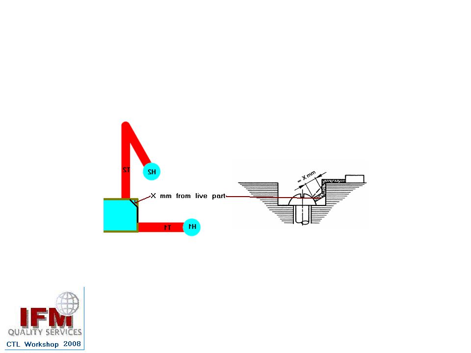
In general, participants did detect the shortest creepage path (within their technical interpretation of the standard). But: the method of negotiating a curved surface was split 50:50 between those following the perimeter of the curve and those traversing across the surface of the curve in a series of X mm jumps (X mm according to the relevant pollution degree)
. But: the method of negotiating a curved surface was split 50:50 between those following the perimeter of the curve and those traversing across the surface of the curve in a series of X mm jumps (X mm according to the relevant pollution degree)")
11
Investigation of the standard revealed
The standard does not cover “curves”. Some participants interpreted a curve as example 2, and others, example 3

12
The dimensions/angle of the cut out is not specified in IEC to the extent that it could be discerned when to apply example 2 and when to apply example 3 A V-shaped groove in example 3 could easily be 90 degrees, and therefore look similar to part of example 2.

13
Product standards Some product standards indicate that when the shape of the surface irregularity exceeds 80 degrees, to follow the perimeter of the surface. (Example 2), and when the angle is less than 80 degrees, the irregularity can be jumped by X mm (Example 3) CTL decision sheet 590 was developed to allow consistent application of the rules. (Apply the X mm jump if the irregularity is less than 80 degrees, even when the relevant product standard does not specify this.)
, and when the angle is less than 80 degrees, the irregularity can be jumped by X mm (Example 3) CTL decision sheet 590 was developed to allow consistent application of the rules. (Apply the X mm jump if the irregularity is less than 80 degrees, even when the relevant product standard does not specify this.)")
14
New program: 07e30 The design challenges:
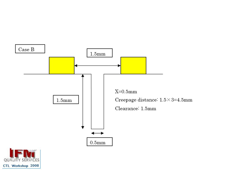
Opportunity to not apply a jump of X mm across a cut out with an angle greater than 80 degrees. (Case A) Opportunity to find a shortest path when more than one option exists (Case B and Case C) Opportunity to apply the jump of X mm because a cut out exists with an angle less than 80 degrees (Case C)
 Opportunity to find a shortest path when more than one option exists (Case B and Case C) Opportunity to apply the jump of X mm because a cut out exists with an angle less than 80 degrees (Case C)")
15
Sample Design

16
Success? Case A – most laboratories correctly did not apply the 80 degree rule Case B – most laboratories correctly chose a suitable path when more than one option existed Case C – most laboratories correctly chose to apply the 80 degree rule where the angle was less than 80 degrees

18
Program Case A Case B Case C

19
Design challenges were met, but
For Case A, some participants applied argued that a jump should have occurred. Approx 0.8mm (<X) Approx 2.0mm
 Approx 2.0mm.")
21
This would be allowed in example 10

23
What if? The screw head ran flush with the groove?

24
Group discussion Taking into consideration that one part of the Case A challenge included a <X mm distance, which example in IEC is most applicable? Review the technical adviser’s points provided on the worksheet In consequence, should a jump of X mm occur or not? Give reasons for your answers

25
Approx 0.8mm (<X) Approx 2.0mm
 Approx 2.0mm")
26
Outcome of group discussion
We don’t understand the standard Example 1, not OK, because of the way pollution accumulates Example 10 does not work for our sample Examples 2 and 3 could be fine Example 3 would work if in a different position, (except for 80 degrees) Not recess or groove, therefore do not bridge it
 Not recess or groove, therefore do not bridge it.")
27
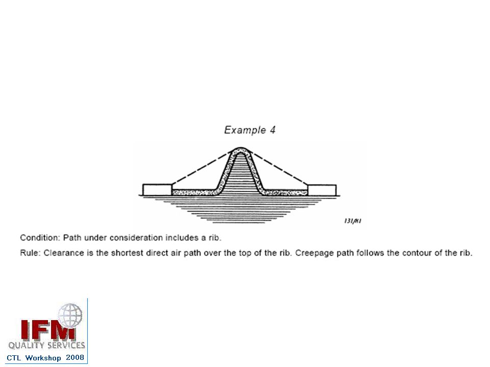
TA thought: If the Standards writers had intended every gap of 1.0mm created by a change of direction of the surface to be bridged they would not have drawn Examples 1, 2, 4, 6, 7, and 9 the way they did. Therefore it must be concluded that they envisaged that there was a point at which the change in surface direction no longer was regarded as a recess.

28
Examples 1, 2, 6, 7, and 9 all show 90 degree groove angles which have not been treated as recesses. Example 4 show angles of around 110 degrees which have not been treated as recesses. The CTL Decision effectively defines the boundary (an angle of 80 degrees) when a change of surface direction creates a recess.
 when a change of surface direction creates a recess..")
29
The judgment of whether Example 10 applies to the PTP sample therefore depends on whether a recess is deemed to exist. In example 10 of the Standard, the screw head which is proud of the insulating surface creates a recess. However, in the extension of the example to the situation in the PTP sample a recess no longer exists, and all that remains is a right-angled groove. It is concluded that Example 10 is not the most appropriate model for the case under consideration.

30
Case B Same as Case A, but with an “extension”

32
Apart from the questions already arising from Case A, most participants completed this part well.
Those not choosing one of options 1 or 2 were given corrective actions to perform.

33
Case C

34
Results for Case C Most laboratories agreed that the corner could be bridged because it had an angle less than 80 degrees. Many, but not all laboratories chose the shortest path from the bridge to T4

36
Discussion: A participant’s results and corrective actions
Creepage Distance T1 – T6 Original Measure Incorrect Path T1 T2 T6 D1 = A-B = 2,2 mm D2 = B-C = 3,3 mm D3 = C-D = 1,6 mm Dt = A-D = D1 + D2 + D3 = 7,1 mm C A B B C d A D

37
OK? Yes/No Creepage distance T1 – T6 New Measure correct Path
B C D D1 = sqrt((A-B)2 + ((B-B’) /2)2) D1 = sqrt((2,2)2 + ((1.6) /2)2) D1 = sqrt(4, ) = 2,3 mm D2 = sqrt(((B-B’)/2)2 + (B’-D)2) D2 = sqrt((1,6/2)2 + 3,32) D2 = sqrt(0, ,9) = 3,4 mm Dt = A-D = D1 + D2 = 5,6 mm C A B D B’
2 + ((B-B’) /2)2) D1 = sqrt((2,2)2 + ((1.6) /2)2) D1 = sqrt(4, ) = 2,3 mm. D2 = sqrt(((B-B’)/2)2 + (B’-D)2) D2 = sqrt((1,6/2)2 + 3,32) D2 = sqrt(0, ,9) = 3,4 mm. Dt = A-D = D1 + D2 = 5,6 mm. C. A. B. D. B’")
38
Participants in the workshop concluded that the corrected measurement was still not correct, as the path, if chosen would only be correct when the exact diagonal from T1-T6 is taken.

39
Creepage Distance T4 – T5 Original Measure Incorrect Path D1 = A-B
D2 = B-C = X D3 = C-D Dt = D1 + D2 + D3 Dt = 1,6 + 0,86 + 1,6 mm = 4,06 mm ; X = 0,86 mm

40
Creepage Distance T4 – T5 New Measure correct Path T4 T5 A D B C

41
The workshop group concluded that corrected pathway was still not correct, as the shortest path to T4 from the cut out was perpendicular to T4.

42
More issues…..

44
Two problems: Use of the word “may” implies that some judgement is required before deciding whether to use clearance÷3 as the X mm distance. There seems to be doubt about the definition of “associated”

45
Participants thought “associated” means:
The actual measured clearance The minimum required clearance A participant provided some interesting evaluations of the sentence.

46
Participant comment

49
Group Exercise C&C1: Exploring associated clearance = actual measured clearance
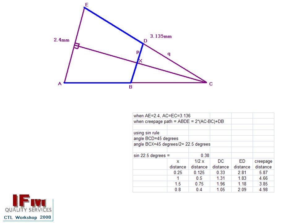
Imagine something similar to 07e30. The angle of the cutout is 45˚. For simplicity T5 ά = ά T4, T4 extends vertically from the cut-out. Distance T4 T5 = 2.4mm Calculate the creepage distance T4 to T5 for PD1, PD2, PD3 and for the case where the clearance is divided by 3. Comment on the effect of the relevant clause in 45˚ ά

51
Group Exercise C&C2: Exploring associated clearance = “required clearance”
Review the text from a participant, and discuss the points raised. Include in the discussion whether you agree of disagree with each point. The practical application of the C/3 reduction when applied for required clearances less than 3mm leads for a the great majority of products marketed (rated voltage less than 300 V) to the case that the exception becomes the rule. The C/3 criteria makes no distinction between pollution degrees which leads, for example, to the case that for pollution degree 1 the result is not to increase the measured creepage distance but to reduce it (while for pollution degree 2 or 3 the application leads to an increase of the measured creepage distance). Another point difficult to understand is the relation with other requirement of the standard IEC 60664: Table 2 indicates in note (3) that for all the lower impulse voltages of the standard the minimum clearance required for pollution degree 2 and 3 are limited not by the overvoltage value but this is limited by the “reduced capacity of the associated creepage distance to support voltage in humid conditions”. This limit is 0,2 mm for PD 2 and 0,8 mm for PD 3. If associated clearance is identified with required clearance, for a typical 230 V equipment with overvoltage category II, the required clearance is 1,5 mm for all pollution degrees. The C/3 value is then 0,5 mm. Comparing this with the data of the previous paragraph, we see that for pollution degree II this could be consistent (0,5mm > absolute minimum of 0,2mm), but for Pollution Degree 3, 0,5mm is less than the 0,8mm absolute minimum required. If it is accepted that a clearance shorter than 0,8 mm could be bridged in a PD 3 environment, then it is not logical to accept that a 0,5 mm clearance can break a creepage trajectory.
 to the case that the exception becomes the rule. The C/3 criteria makes no distinction between pollution degrees which leads, for example, to the case that for pollution degree 1 the result is not to increase the measured creepage distance but to reduce it (while for pollution degree 2 or 3 the application leads to an increase of the measured creepage distance). Another point difficult to understand is the relation with other requirement of the standard IEC 60664: Table 2 indicates in note (3) that for all the lower impulse voltages of the standard the minimum clearance required for pollution degree 2 and 3 are limited not by the overvoltage value but this is limited by the reduced capacity of the associated creepage distance to support voltage in humid conditions . This limit is 0,2 mm for PD 2 and 0,8 mm for PD 3. If associated clearance is identified with required clearance, for a typical 230 V equipment with overvoltage category II, the required clearance is 1,5 mm for all pollution degrees. The C/3 value is then 0,5 mm. Comparing this with the data of the previous paragraph, we see that for pollution degree II this could be consistent (0,5mm > absolute minimum of 0,2mm), but for Pollution Degree 3, 0,5mm is less than the 0,8mm absolute minimum required. If it is accepted that a clearance shorter than 0,8 mm could be bridged in a PD 3 environment, then it is not logical to accept that a 0,5 mm clearance can break a creepage trajectory.")
52
Comments that IEC 60664-1 is “too hard”
Bearing the purpose of the test in mind, we will look at each rule individually, try to discern the differences between each, with the aim of either: Devising a flow chart that simplifies Creepage determinations, or Recommending suitable alternative presentation of the rules to the TC . Start with “These cases do not differentiate between gaps and grooves or between types of insulation.”

53
Dictionary (on-line) gap groove recess
Oxford -a break or hole in an object or between two objects. 2 a space, interval, or break. Encarta - break in structure: a break or opening in a structure or arrangement such as a fence or military defense line Webster - 5: a break in continuity groove Oxford - a long, narrow cut or depression in a hard material. Encarta - narrow passage: a narrow channel or path in a surface Webster - a long narrow channel or depression recess Oxford - a small space set back in a wall. 2 a hollow in something. 3 (recesses) remote, secluded, or secret places. Encarta - remote place: a remote or secluded place Webster – indentation (an angular cut in an edge ), cleft
 remote, secluded, or secret places. Encarta - remote place: a remote or secluded place. Webster – indentation (an angular cut in an edge ), cleft.")
54
Is a recess a short groove?
Given the standard indicates there is no distinction between gaps and grooves - could a gap also be a recess? Are they all surface irregularities? (all subject to pollution accumulation) Should they treated in the same manner?
 Should they treated in the same manner")
Similar presentations