Download presentation
Presentation is loading. Please wait.

1
STATNAMIC LOAD TESTING
Development, Interpretation of Results, Advantages

2
Presentation Outline Pile Load Testing - background
Brief Statnamic Introduction Recent activities in the US Statnamic Theory and Analysis Recent activities in Taiwan 20MN testing at the TFC project, Taiwan other notable jobs Standardisation of “RAPID” Load Testing Q&A and Discussion

3
Quick Statnamic Facts 21 Statnamic devices world-wide
12 Statnamic testing companies Over 1200 contract Statnamic load tests performed in 16 countries - more than one test every day, somewhere in the world! Over 80 published papers, including papers from 2 International Statnamic Seminars More than 10 Universities currently researching Statnamic (USA - Auburn, USF, BYU, Umass, John Hopkins, plus others) Acceptance by 16 State DOT’s in the US, US Army Corps of Engineers, FHWA, and Japanese Geotechnical Society
 Acceptance by 16 State DOT’s in the US, US Army Corps of Engineers, FHWA, and Japanese Geotechnical Society.")
4
Pile Load Testing Background

6
STATIC TEST - Reaction piles

7
Features of STATIC Load Tests

10
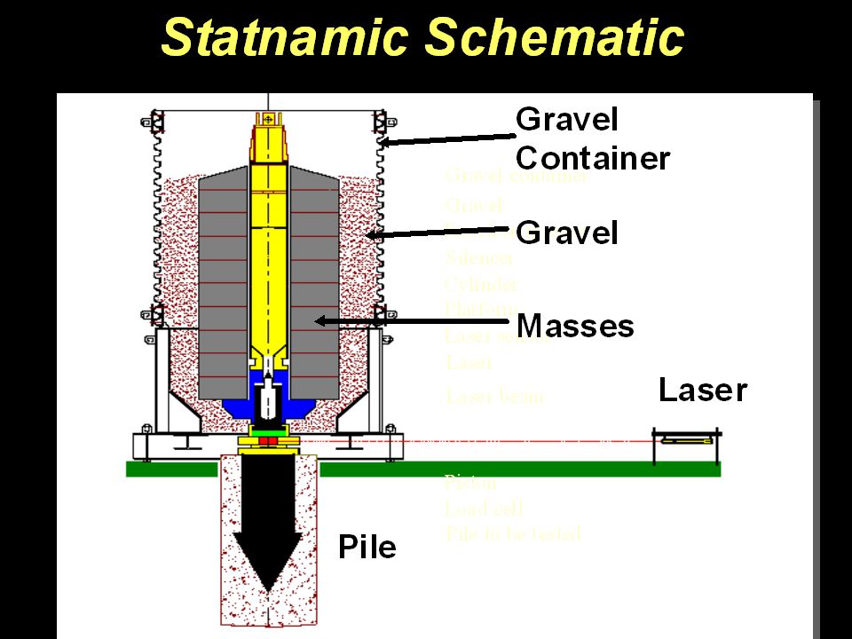
Statnamic

12
The Idea Statnamic Note: The JGS defines a Rapid Load Test as 5 < tr < 500, where tr is the number of times a stress wave will travel up and down the pile during the loading event

13
Inertial Load Testing (Bermingham - 1987)
This type of test was clearly different from a Dynamic Load Test A NEW WORD WAS REQUIRED!! Inertial Load Testing (Bermingham ) STATNAMIC (Middendorp - (1989)) Pseudo-static (Fundex PS PLT - early 1990’s) Kinetic (Holeyman ) Rapid Load Test (Japanese Study Group ) Transient Long-period (Janes -1997) Slow dynamic (Goble, Rausche ) others - impulse, kinematic, push, etc.
 STATNAMIC (Middendorp - (1989)) Pseudo-static (Fundex PS PLT - early 1990’s) Kinetic (Holeyman ) Rapid Load Test (Japanese Study Group ) Transient Long-period (Janes -1997) Slow dynamic (Goble, Rausche ) others - impulse, kinematic, push, etc.")
14
...a global perspective... In March of 2000, the Japanese Geotechnical Society added “Rapid Load Testing” to their national standard for pile testing. In the year 2000, it is estimated that there will be more than 500 Statnamic Load Tests on foundations around the world.

18
Newark Airport - 3,500 ton Statnamic Test

19
1800 tons Japan Test Pile as Support Pile

21
300 ton Statnamic Testing in Holland

22
500 ton Testing at JFK Airport, New York, N.Y.

24
Mechanical Catching Mechanism (2000)
")
25
1800 ton Test Pile as Support Pile Mechanical Catching Mechanism

26
Recent Activities in the USA
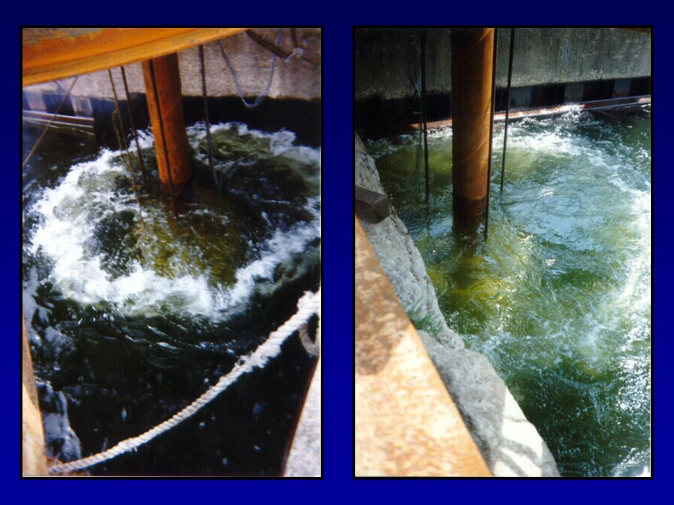
Use of Water as Reaction Mass

27
Concept

28
Experiments at Berminghammer’s Yard in Canada, ‘98

31
First Contract Test - Lake Charles, Louisiana

35
Statnamic Hammer (in development)
")
36
Recent Activities in the USA
Lateral Load Testing

38
400 ton Lateral Testing - Auburn, Alabama

39
800 ton Lateral Testing - Mississippi

40
Lateral Test Programs in the US
New Bern, North Carolina DOT (50 tons) Brigham Young University - (200 tons) Utah DOT & CALTRANS Auburn University, Alabama - (250 tons) (FHWA) Pascagoula, Mississippi DOT (800 tons, over-water) Providence, Rhode Island DOT (400 tons, over-water) San Juan, Puerto Rico Trans Authority (400 tons) New Bern, North Carolina DOT (1200 tons, over-water)
 Brigham Young University - (200 tons) Utah DOT & CALTRANS. Auburn University, Alabama - (250 tons) (FHWA) Pascagoula, Mississippi DOT (800 tons, over-water) Providence, Rhode Island DOT (400 tons, over-water) San Juan, Puerto Rico Trans Authority (400 tons) New Bern, North Carolina DOT (1200 tons, over-water)")
41
“Statnamic” Earthquake Generator (John Hopkins University & FHWA)
")
42
Foundation Types Tested in the USA Using Statnamic
Drilled Shafts tested up to 3500 tons laterally and axially Driven Piles (all types) Pile Groups tested laterally and axially Stone Columns Auger-Cast Piles conventional and ‘displacement’ types Spread Footings and Plates Other types of “Ground Modification”
 Pile Groups. tested laterally and axially. Stone Columns. Auger-Cast Piles. conventional and ‘displacement’ types. Spread Footings and Plates. Other types of Ground Modification")
43
Background Statnamic Theory and Analysis
GOAL: to derive the STATIC load displacement behavior from a STATNAMIC load test (usual goal for axial compression testing)
")
44
Supporting evidence…stress waves?
Pile Toe Applied Force (RLT) Pile Head
 Pile Head.")
45
Supporting evidence…stress waves?
Pile Head Pile Toe

46
Supporting evidence…stress waves?
Pile Head Pile Toe

47
Physical Model m c k F u In a STATNAMIC LOAD TEST:
F = Applied force from the Statnamic device (measured by a load cell) m = Pile mass (easy to calculate) c = pile/soil damping (UNKNOWN) k = pile and soil stiffness (the term we need to find) u, v, a = measured by an optical sensor and/or accelerometer
 m = Pile mass (easy to calculate) c = pile/soil damping (UNKNOWN) k = pile and soil stiffness (the term we need to find) u, v, a = measured by an optical sensor and/or accelerometer.")
48
Physical Model F = ma + cv + ku GENERAL LIMITATIONS:
This equation makes the following assumptions: 1. Inertia (mass x acceleration) - assumes that a single value of ‘m’ (the pile mass) represents all of the moving mass in the system 2. Damping (damping coefficient x velocity) - assumes that a single value of ‘c’ is valid throughout the entire load test, and that the damping force is directly proportional to velocity 3. Stiffness (stiffness coefficient x displ.) - the calculated stiffness is the stiffness of the pile and soil system under a RAPID load - no correction is made for long-term, time-dependent pile behavior, which includes effects such as changes in pore-pressure and creep F = ma + cv + ku
 - assumes that a single value of ‘m’ (the pile mass) represents all of the moving mass in the system. 2. Damping (damping coefficient x velocity) - assumes that a single value of ‘c’ is valid throughout the entire load test, and that the damping force is directly proportional to velocity. 3. Stiffness (stiffness coefficient x displ.) - the calculated stiffness is the stiffness of the pile and soil system under a RAPID load - no correction is made for long-term, time-dependent pile behavior, which includes effects such as changes in pore-pressure and creep. F = ma + cv + ku.")
49
Structural Analogy F = ku (Static) F = ma + cv + ku (Statnamic) Static
Dynamic m F F = ku (Static) F = ma + cv + ku (Statnamic) u k F
 F = ma + cv + ku. (Statnamic) u. k. F.")
50
Physical Model F = ma + cv + ku c m k F u EQUATION OF MOTION:
This equation describes the equilibrium between some forcing function and the 3 forces: Inertia (mass x acceleration) Damping (damping coefficient x velocity) Stiffness (stiffness coefficient x displ.) This equation forms the basis for describing the motion of any single degree of freedom system. F = ma + cv + ku
 Damping (damping coefficient x velocity) Stiffness (stiffness coefficient x displ.) This equation forms the basis for describing the motion of any single degree of freedom system. F = ma + cv + ku.")
51
Analysis Assuming that stress-waves can be ignored, the analysis of a Statnamic Load Test is greatly simplified in comparison to a dynamic load test. Although stress-waves may be ignored, the ‘dynamic’ effects of INERTIA and DAMPING CANNOT! Result: a detailed model, which includes pile and soil properties IS NOT NEEDED. A simple physical model can be used to remove the effects of damping and inertia from the measured signals - no information about the soil is needed, and subjective judgement is minimized.

52
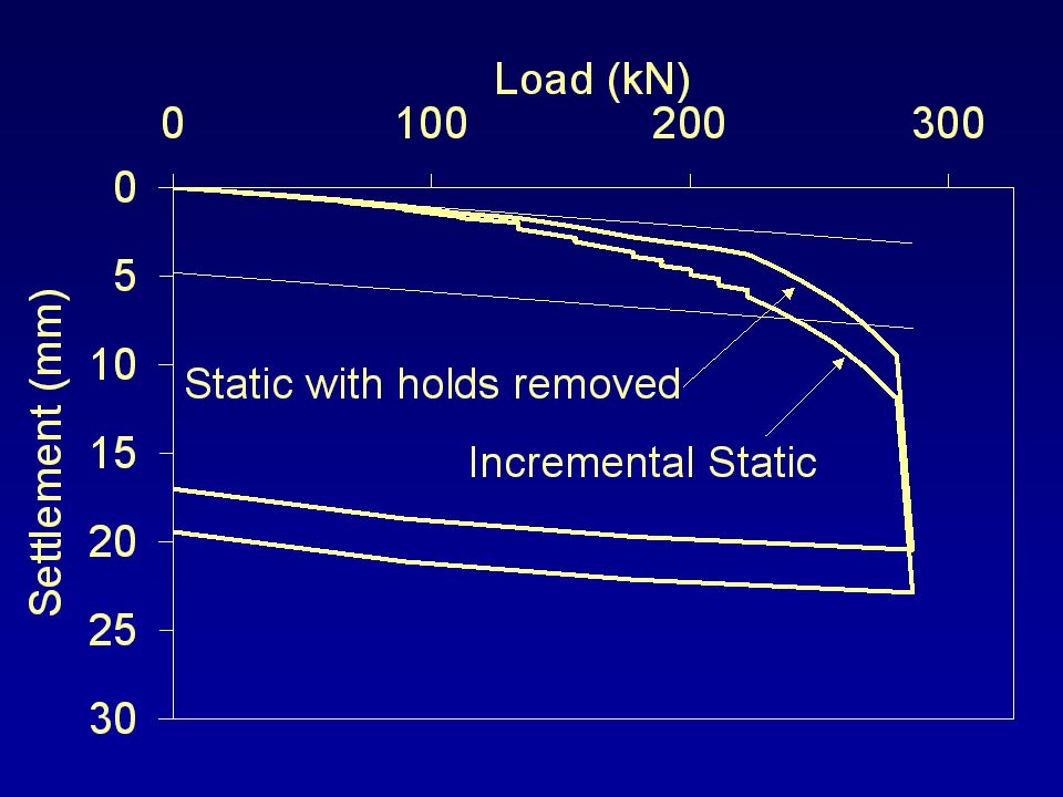
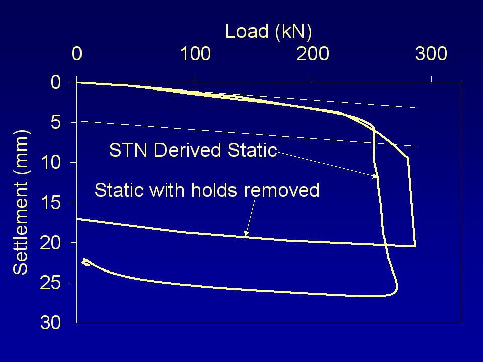
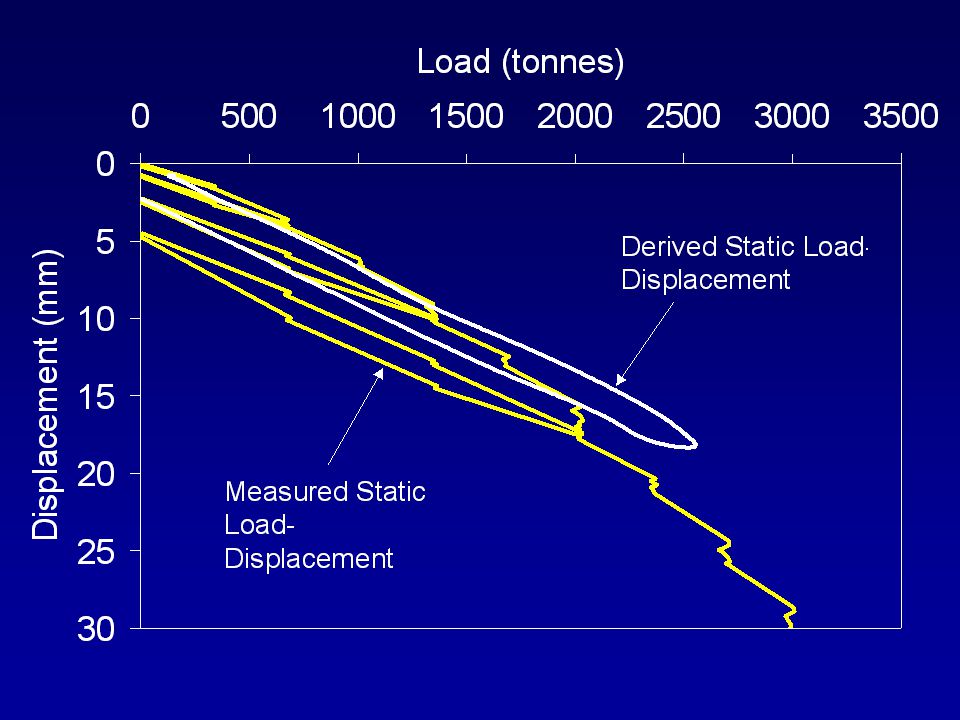
”Derived Static” from Statnamic
Measured Statnamic Derived Static ”Derived Static” from Statnamic

53
Statnamic Force, Inertia Force, & Damping Force
(ms) Statnamic Force, Inertia Force, & Damping Force
 Statnamic Force, Inertia Force, & Damping Force.")
54
Statnamic & Derived Static Force
(ms) Statnamic & Derived Static Force
 Statnamic & Derived Static Force.")
55
14 m Driven Concrete Pile in Sand
Static - 3 cycles Statnamic 14 m Driven Concrete Pile in Sand

60
Recent Activities in the USA
Testing Stone Columns

61
Stone Column Group (250 tons)
")
63
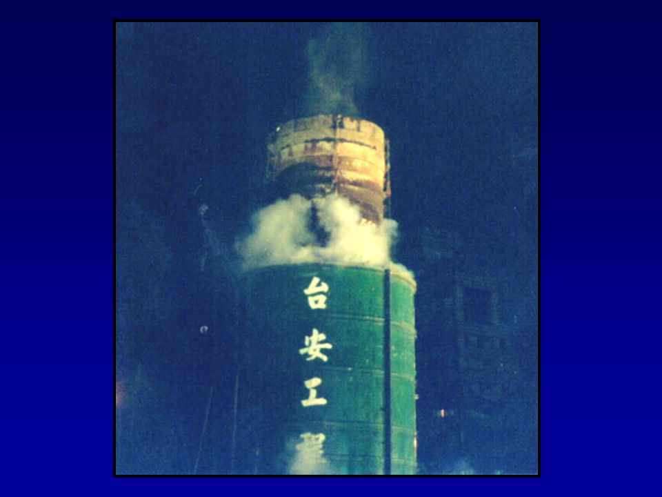
Recent Activities in Taiwan
2000 ton Testing at the Taipei FinancialCenter

65
STATIC TEST - Reaction piles

72
Notable Projects from Around the World

73
Library of Alexandria, Egypt

75
Quay West Apartments, Melbourne, Australia

77
Hanshin Expressway, Kobe, Japan

78
Standards

79
Standardisation of RAPID Load Testing
Recommendations on STN testing of PILES in soil and rock (FHWA) Japanese Geotechnical Society, Standard for Rapid Load Testing (2000) ASTM - Standard for Rapid Axial Compressive Load (2008) Florida LRFD Design Guidelines
 Japanese Geotechnical Society, Standard for Rapid Load Testing (2000) ASTM - Standard for Rapid Axial Compressive Load (2008) Florida LRFD Design Guidelines.")
80
mjustason@berminghammer.com www.berminghammer.com
The End.

Similar presentations