Download presentation
Presentation is loading. Please wait.

1
ANODE CATALYSTS FOR LOW TEMPERATURE FUELL CELLS
Branimir N. Grgur Faculty of Technology and Metallurgy, University of Belgrade, Karnegijeva 4, Belgrade, Serbia,

2
DaimlerChrysler B-Class F-Cell (Hydrogen/Oxygen)
Unvieled at the 2005 Geneva Motorshow this new generation of F-Cell has a power output of over 100 kW and a driving range of over 400 km.

3
Possible source of H2, methanol reforming?
Fuel Cell Functionality Fuel cells generate electricity from a simple electrochemical reaction in which an oxidizer, typically oxygen from air, and a fuel, typically hydrogen, combine to form a product, which is water for the typical fuel cell. Oxygen (air) continuously passes over the cathode and hydrogen passes over the anode to generate electricity, by-product heat and water. The fuel cell itself has no moving parts – making it a quiet and reliable source of power. Anode Reaction: 2H2 = 4H+ + 4e Cathode Reaction: O2 + 4H+ + 4e = 2H2O Overall Cell Reaction: 2H2 + O2 = 2H2O Hydrogen - explosive - cost of H2 production? - difficult to storage Possible source of H2, methanol reforming?
 continuously passes over the cathode and hydrogen passes over the anode to generate electricity, by-product heat and water. The fuel cell itself has no moving parts – making it a quiet and reliable source of power. Anode Reaction: 2H2 = 4H+ + 4e. Cathode Reaction: O2 + 4H+ + 4e = 2H2O. Overall Cell Reaction: 2H2 + O2 = 2H2O. Hydrogen. - explosive. - cost of H2 production - difficult to storage. Possible source of H2, methanol reforming")
4
Fig. 1. Cell voltage - current dependencies
Low temperature fuel cells based on polymer electrolytes (polymer electrolytes fuel cells, PEFC) are today one of the most promising electrochemical power sources for application in transportation and portable power generation. Hydrogen generated by steam reforming of methanol, with a typical reformer gas composition ~75 % H2, ~25 % CO2 and 1-2 % CO, was widely considered as a fuel in the low temperature fuel cells. A major problem in the development of PEFC has been the deactivation of Pt anode, as a best hydrogen electrooxidation catalyst, by even trace level, e.g ppm, of carbon monoxide. Without CO in the gas mixtures, cell voltage, U, of the system based on hydrogen oxidation and oxygen reduction reaction on platinum catalyst is between 1 and 0.8 V depending on the output cell current, as shown in Fig. 1.Operating cell voltage is smaller than theoretical one of a 1.23 V, mostly because of slow oxygen reduction kinetics. In the presence of 0.1% CO in hydrogen fuel, doted line in Fig 1, anode voltage loss is 0.5 to 0.6 volts, and cell voltage is reduced to only 0.4 to 0.5 volts, which is unacceptable high loss. Fig. 1. Cell voltage - current dependencies of fuel cell reaction.
 are today one of the most promising electrochemical power sources for application in transportation and portable power generation. Hydrogen generated by steam reforming of methanol, with a typical reformer gas composition ~75 % H2, ~25 % CO2 and 1-2 % CO, was widely considered as a fuel in the low temperature fuel cells. A major problem in the development of PEFC has been the deactivation of Pt anode, as a best hydrogen electrooxidation catalyst, by even trace level, e.g ppm, of carbon monoxide. Without CO in the gas mixtures, cell voltage, U, of the system based on hydrogen oxidation and oxygen reduction reaction on platinum catalyst is between 1 and 0.8 V depending on the output cell current, as shown in Fig. 1.Operating cell voltage is smaller than theoretical one of a 1.23 V, mostly because of slow oxygen reduction kinetics. In the presence of 0.1% CO in hydrogen fuel, doted line in Fig 1, anode voltage loss is 0.5 to 0.6 volts, and cell voltage is reduced to only 0.4 to 0.5 volts, which is unacceptable high loss. Fig. 1. Cell voltage - current dependencies. of fuel cell reaction.")
5
Fig. 2. The energy level of carbon monoxide molecules,
This problem arise due to the strong CO adsorption on the platinum surfaces (COads), which lead to the “poisoning” of active sites for hydrogen oxidation reaction. Such strong binding has been explained by Blyholder by electron donation from 5s carbon monoxide orbital to metal, and subsequent transfer of two electrons from d metal atomic orbital to the antibindig 2p* CO orbital, as shown on Fig. 2. This electron transfer is known as beck-donation. Fig. 2. The energy level of carbon monoxide molecules, and formation of metal-carbon monoxide bonding.
, which lead to the poisoning of active sites for hydrogen oxidation reaction. Such strong binding has been explained by Blyholder by electron donation from 5s carbon monoxide orbital to metal, and subsequent transfer of two electrons from d metal atomic orbital to the antibindig 2p* CO orbital, as shown on Fig. 2. This electron transfer is known as beck-donation. Fig. 2. The energy level of carbon monoxide molecules, and formation of metal-carbon monoxide bonding.")
6
To remove COads from the surface it is necessary to generate some oxygenated species that can react with COads producing CO2 and to release some free sites on Pt surfaces for hydrogen oxidation reaction. The mechanism for the oxidative removal of the COads from platinum anodes has been a topic of intense investigation for the past 40 years. The overall reaction for removing COads is COads + H2O = CO2 +2H+ + 2e (1) The mechanism of hydrogen oxidation in the H2/CO mixtures on platinum can be given by the following sequences: COb + Pt Pt-COads (4) Pt + H2O = Pt-OHads + H+ + e (5) Pt-COads + Pt-OHads CO2 + H+ + 2Pt + e (6) 2Pt + H2 = 2Pt-2Hads (7) 2Pt-2Hads = 2Pt + 2H+ + 2e (8) Hydrogen oxidation reaction occurs on the free sites liberated during the time between COads oxidative removal, Eq. (6) and CO readsorption from solution, Eq. (4). At the low potential (E< ~0.6 V) the rate constant of COb readsorption is much higher then the rate constant for COads oxidation, and practically only the infinitely small number of platinum sites could be liberated, for H2 oxidation.
 The mechanism of hydrogen oxidation in the H2/CO mixtures on platinum can be given by the following sequences: COb + Pt Pt-COads (4) Pt + H2O = Pt-OHads + H+ + e (5) Pt-COads + Pt-OHads CO2 + H+ + 2Pt + e (6) 2Pt + H2 = 2Pt-2Hads (7) 2Pt-2Hads = 2Pt + 2H+ + 2e (8) Hydrogen oxidation reaction occurs on the free sites liberated during the time between COads oxidative removal, Eq. (6) and CO readsorption from solution, Eq. (4). At the low potential (E< ~0.6 V) the rate constant of COb readsorption is much higher then the rate constant for COads oxidation, and practically only the infinitely small number of platinum sites could be liberated, for H2 oxidation.")
7
Fig. 3. Bi-functional catalyst (schematic representation).
The hydrogen oxidation reaction reaches maximum at the same potential where COads is oxidized by Pt-OH (coverage with COads in that potential region tends to zero). According to this, it is necessary to provide supply of OH species to adjunct platinum atoms covered by COads by some other metal, which does not adsorb CO. This catalyst is known as bi-functional catalyst. Schematic representation of such catalyst is given in Fig. 3. Fig. 3. Bi-functional catalyst (schematic representation).
. According to this, it is necessary to provide supply of OH species to adjunct platinum atoms covered by COads by some other metal, which does not adsorb CO. This catalyst is known as bi-functional catalyst. Schematic representation of such catalyst is given in Fig. 3. Fig. 3. Bi-functional catalyst. (schematic representation).")
8
As the alloying metal (M) should provide –OH for the reaction with COads:
Pt-COads + OH-M Pt + M + CO2 + H+ + e (9) it is necessary to find such metal which can provide OH on the as low as possible potential (e.g. near the hydrogen reversible potential). Although, practically all transition metals are oxidized in the acid solutions, the fact is that only few metals in alloy with platinum shows certain activity for oxidation of H2/CO mixtures. In eighties, encouraging catalytic performance has been reported for Pt-Ru, Pt-Sn alloy electrodes in the electrooxidation of H2/CO mixtures. Unfortunately, even with these catalysts and low level of CO, ~100 ppm in a H2/CO fuel, voltage losses in a real PEFC are too high, (for PtRu alloy ~0.4 V at 0.6 A cm-2). This is due adsorption of CO on Ru sites as well, blocking the sites for OH nucleation.
 it is necessary to find such metal which can provide OH on the as low as possible potential (e.g. near the hydrogen reversible potential). Although, practically all transition metals are oxidized in the acid solutions, the fact is that only few metals in alloy with platinum shows certain activity for oxidation of H2/CO mixtures. In eighties, encouraging catalytic performance has been reported for Pt-Ru, Pt-Sn alloy electrodes in the electrooxidation of H2/CO mixtures. Unfortunately, even with these catalysts and low level of CO, ~100 ppm in a H2/CO fuel, voltage losses in a real PEFC are too high, (for PtRu alloy ~0.4 V at 0.6 A cm-2). This is due adsorption of CO on Ru sites as well, blocking the sites for OH nucleation.")
9
The inactivity of different Pt-M alloys could be searched in the metal to oxygen bond strength, and in the corrosion behavior of alloys. Electronegative alloying metals such are Ti, V, Nb, Ta ect. have to strong bond strength (practically in the form of the metal oxides) so this metals cannot provide oxygenated species for COads oxidation. Some noble metals could provide oxygenated species which can oxidize COads (e.g. Ru, Ir, Au) but the potential where this metals are in the form of oxy-hydroxide is to high for the application as the anode in the fuel cells. From the other hand the transition metals (Fe, Co, Ni, Mn) and some other metals and metalloids as Zn, Cd, Ga, Bi, In, Sb, Ge are in the form of oxy-hydroxide at the low potentials ~ 0 V vs. RHE, but unfortunately most of the platinum alloys with this metals are corrosion unstable or during the thermal preparation of alloys strong segregation and enrichment in platinum in to the surface layer occur, and alloys have platinum like behavior. By analyzing the metal to oxygen bond strength and thermodynamic data of metal oxidation in acid solution it has been concluded that platinum alloys with molybdenum or tungsten could be the metal of choice. Platinum-molybdenum alloy has been chosen for the further investigation mostly because tungsten has to high melting point (3410oC) and it is difficult to prepare the alloy with platinum.
 so this metals cannot provide oxygenated species for COads oxidation. Some noble metals could provide oxygenated species which can oxidize COads (e.g. Ru, Ir, Au) but the potential where this metals are in the form of oxy-hydroxide is to high for the application as the anode in the fuel cells. From the other hand the transition metals (Fe, Co, Ni, Mn) and some other metals and metalloids as Zn, Cd, Ga, Bi, In, Sb, Ge are in the form of oxy-hydroxide at the low potentials ~ 0 V vs. RHE, but unfortunately most of the platinum alloys with this metals are corrosion unstable or during the thermal preparation of alloys strong segregation and enrichment in platinum in to the surface layer occur, and alloys have platinum like behavior. By analyzing the metal to oxygen bond strength and thermodynamic data of metal oxidation in acid solution it has been concluded that platinum alloys with molybdenum or tungsten could be the metal of choice. Platinum-molybdenum alloy has been chosen for the further investigation mostly because tungsten has to high melting point (3410oC) and it is difficult to prepare the alloy with platinum..")
10
On Fig. 4 the polarization curves for 2% CO and 2% CO/H2 mixtures on Pt, PtRu, Pt3Sn, Pt3Mo and Pt3Re electrodes are shown. It is obvious that H2 oxidation follows the CO oxidation, which is in agreement with above given discussion. At the potential of interests (~0.2 V), Pt-Mo shows the best activity. Fig. 4 Polarization curves for 2% CO/Ar and 2% CO/H2 mixtures
, Pt-Mo shows the best activity. Fig. 4 Polarization curves for. 2% CO/Ar and 2% CO/H2 mixtures.")
11
Development of the anode fuel cell catalysts, few steps should be follows:
1. Preparation and characterization of the catalysts. 2. Investigations of the hydrogen oxidation reaction. 3. Investigation of CO and CO/H2 oxidation reaction. 4. Preparation of supported catalysts and testing in the laboratory and in the real fuel cell. 5. Mechanistic studies.

12
1. Preparation and characterization of the catalysts.
First step in development of the anode catalyst is preparation. Catalyst can be prepared by melting, arc-melting in argon atmosphere, ion-beam implantation ect. followed by the heat treatment for homogenization. After preparation alloy sample should be mechanically grounded into a cylindrical shape to fit in Teflon or Kel-F holder for rotating disk electrode (RDE). After preparation, alloy sample should be characterized by means of some surface and UHV techniques (AES, LEIS, XPS). Usually, X-ray diffraction is the most common characterization to obtain bulk composition and structure. In some cases due to the strong segregations during the heat treatment, surface composition can differ from bulk composition. An example of that are PtMo alloy. The bulk composition of alloy was 66 mol.% Pt and 33 mol.% Mo (Pt2Mo). But after UHV annealing treatment at 970 K for 30 min. resulting surface concentration of Mo was 23 mol.%, and after Ar ion (0.5 keV) spattering 30 mol.%, as shown in Fig. 5.
. After preparation, alloy sample should be characterized by means of some surface and UHV techniques (AES, LEIS, XPS). Usually, X-ray diffraction is the most common characterization to obtain bulk composition and structure. In some cases due to the strong segregations during the heat treatment, surface composition can differ from bulk composition. An example of that are PtMo alloy. The bulk composition of alloy was 66 mol.% Pt and 33 mol.% Mo (Pt2Mo). But after UHV annealing treatment at 970 K for 30 min. resulting surface concentration of Mo was 23 mol.%, and after Ar ion (0.5 keV) spattering 30 mol.%, as shown in Fig. 5.")
13
XPS- bulk composition, chemical shifts, oxidation states of metals
Fig. 5. Derivative mode AES spectrum of the PtMo following sputter-cleaning and annealing at 970 K. Insert: LEIS spectra of the same surfaces. XPS- bulk composition, chemical shifts, oxidation states of metals

14
2. Investigations of the hydrogen oxidation reaction.
The first condition that an catalysts could be used as fuel cell anode is a good catalytic properties in hydrogen oxidation reaction. After recording the cyclic voltammograms, the solution was saturated with H2 and hydrogen oxidation reaction was examined, as shown in Fig 6. At Pt85Mo15 and Pt77Mo23 electrode reaction rates are identical with the oxidation of hydrogen on pure Pt. The overpotential/current relation closely follows that for pure diffusion control: = (RT/2F) log (1-j/jd) (10) where jd is the measured diffusion-limited current density at any rotation rate and j is the observed current density at overpotential .
 log (1-j/jd) (10) where jd is the measured diffusion-limited current density at any rotation rate and j is the observed current density at overpotential .")
15
While a relatively small surface concentration of Mo (15 and 23 mol
While a relatively small surface concentration of Mo (15 and 23 mol.%) atoms has no effect (practically unmeasurable by standard RDE methods) on the hydrogen oxidation reaction, the HOR is dramatically inhibited on the Pt70Mo30 surface. Figure 6 shows that below 0.4 V the polarization curve practically have no rotation rate dependence, characteristic for pure diffusion control. This implies reaction control with probably Tafel (chemical) reaction as a rate-determining step. Above 0.4 V, some increase of the current density and rotation rate dependencies has been observed, but more likely as mixed diffusion-reaction control. Above 0.6 V, the current density decrease again which is connected with oxidation of Pt atoms on the surface. This dramatic change in the shape of polarization curve is strongly connected with the chemistry of Mo atoms at the surface. Fig. 6. Cyclic voltammograms (50 mV s-1) in deaerate 0.5 H2SO4 of the different surfaces (market at the figure) and polarization curves (1 mV s-1) in H2 saturated electrolyte at 333 K at different rotation rates
 atoms has no effect (practically unmeasurable by standard RDE methods) on the hydrogen oxidation reaction, the HOR is dramatically inhibited on the Pt70Mo30 surface. Figure 6 shows that below 0.4 V the polarization curve practically have no rotation rate dependence, characteristic for pure diffusion control. This implies reaction control with probably Tafel (chemical) reaction as a rate-determining step. Above 0.4 V, some increase of the current density and rotation rate dependencies has been observed, but more likely as mixed diffusion-reaction control. Above 0.6 V, the current density decrease again which is connected with oxidation of Pt atoms on the surface. This dramatic change in the shape of polarization curve is strongly connected with the chemistry of Mo atoms at the surface. Fig. 6. Cyclic voltammograms (50 mV s-1) in deaerate 0.5 H2SO4 of the different surfaces. (market at the figure) and polarization curves. (1 mV s-1) in H2 saturated electrolyte at 333 K. at different rotation rates.")
16
3. Investigation of CO and CO/H2 oxidation reaction.
The second condition that an catalysts could be used as fuel cell anode is a good catalytic properties in oxidation of CO/H2 mixtures. Figure 7 shows the quasi-steady state (1 mV/s) polarization curves of 0.1 % CO/H2 mixtures on the three different PtMo bulk alloy surfaces and Pt in 0.5 M H2SO4. In order to assure the equilibration of the electrode surfaces with CO prior to the recording the polarization curve, the electrode was held at 0.1 V for 3000 s (see the insert of Fig. 8) at a rotation rate of 2500 rpm, followed by potential scan from 0 V.
 polarization curves of 0.1 % CO/H2 mixtures on the three different PtMo bulk alloy surfaces and Pt in 0.5 M H2SO4. In order to assure the equilibration of the electrode surfaces with CO prior to the recording the polarization curve, the electrode was held at 0.1 V for 3000 s (see the insert of Fig. 8) at a rotation rate of 2500 rpm, followed by potential scan from 0 V.")
17
Fig. 7. Polarization curves (1 mV s-1) for
the oxidation of 0.1% CO in hydrogen on different PtMo surfaces and pure Pt in 0.5 M H2SO4 at 2500 rpm, 333 K, followed by 3000 s of poisoning at 0.1 V. Fig. 8. Polarization curve for the oxidation of H2 on the Pt77Mo23 alloy surface containing various levels of CO. Insert: Time dependence of the current density at 0.1 V following a switch from pure H2 to H2/CO mixtures.

18
4. Preparation of supported catalysts and testing in the laboratory and in the real fuel cell.
Once, when some alloy shows potentially good activity, it should be prepared as carbon supported catalyst and tested in the real conditions. Preparation methods can differ depending on the alloy, and some principles can be found in Ref. [16] [K. Kinoshita, Electrochemical Oxygen Technology, The Electrochemical Society Series, Pennington, N. J., 1992]. For testing such catalyst in the laboratory cell easy rotating disk method developed by Schmidt at al. [T.J. Schmidt, H.A. Gasteiger, G.D. Stab, P.M. Urban, D.M. Kolb, R.J. Behm, J. Electrochem. Soc. 145 (1998) 2354] can be applied. Briefly, the thin catalysts layers were prepared by attaching ultrasonically redispersed catalysts suspension in distilled water onto the glassy carbon or gold RDE, resulting in a constant metal loading in the range of of μg cm-2.After drying in flowing high purity argon at room temperature, the deposited catalyst layer was then covered with a diluted aqueous-methanol Nafion® solution.
 2354] can be applied. Briefly, the thin catalysts layers were prepared by attaching ultrasonically redispersed catalysts suspension in distilled water onto the glassy carbon or gold RDE, resulting in a constant metal loading in the range of of μg cm-2.After drying in flowing high purity argon at room temperature, the deposited catalyst layer was then covered with a diluted aqueous-methanol Nafion® solution.")
19
Partial pressure effect
CV Hydrogen oxidation Kinetics study Partial pressure effect

20
Knowing the metal loading it is possible to simulate real fuel cell conditions

21
Second, but long term method is formation of small scale real fuel cell. In such cell cathode should be the same for comparison, and anode should be exchangeable. By trying different anode at the same operating conditions, as shown on Fig. 9, voluble conclusions can be drown, like dependence of cell voltage on applied current density, possible deactivation of catalytic properties etc.

22
5. Mechanistic studies. Determination of the mechanism in the CO/H2 oxidation reaction is not necessary, but could be very useful in complete understanding of catalyst behavior. One example is possible mechanism of CO/H2 oxidation on PtMo alloy. Based on the experimental evidences, the following mechanism for CO oxidation at low potential region on PtMo alloy could be given as follows: (12) (13) (14) where: kads(CO) and kdes(CO) are rate constants for CO adsorption and desorption; kox(CO) and kred(CO2) are rate constants for COads oxidation and CO2 reduction; kox andi kred are rate constants for Mo(OH)2 oxidation and Mo(OH)3 reduction. Rate determining step (r.d.s) reaction given by Eq. (13) is proposed.
 (13) (14) where: kads(CO) and kdes(CO) are rate constants for CO adsorption and desorption; kox(CO) and kred(CO2) are rate constants for COads oxidation and CO2 reduction; kox andi kred are rate constants for Mo(OH)2 oxidation and Mo(OH)3 reduction. Rate determining step (r.d.s) reaction given by Eq. (13) is proposed.")
23
For the steady state conditions the change of COads coverage in Eq
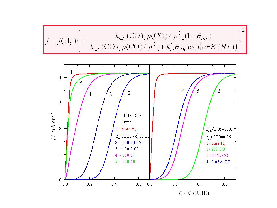
For the steady state conditions the change of COads coverage in Eq. (14) can be given as: (15) where kox(CO) is potentially dependent rate constant: kox(CO)=k*ox(CO) exp (16) (k*ox(CO) is chemical rate constant and is the transfer coefficient). After rearranging Eq. (15) with neglecting the kred(CO2) and kdes(CO), the COads coverage is given by: (17) Considering a simple site-blocking model for the poisoning of H2 by adsorbed CO, given by: j = j(H2) [1-(CO)]n (18) where j is the measured current in the presence of CO, j(H2) is the limiting diffusion current for pure H2 oxidation, so, j in the presence of CO can be given by substituting (CO) from (17) in (18):
 can be given as: (15) where kox(CO) is potentially dependent rate constant: kox(CO)=k*ox(CO) exp (16) (k*ox(CO) is chemical rate constant and is the transfer coefficient). After rearranging Eq. (15) with neglecting the kred(CO2) and kdes(CO), the COads coverage is given by: (17) Considering a simple site-blocking model for the poisoning of H2 by adsorbed CO, given by: j = j(H2) [1-(CO)]n (18) where j is the measured current in the presence of CO, j(H2) is the limiting diffusion current for pure H2 oxidation, so, j in the presence of CO can be given by substituting (CO) from (17) in (18):")
24
(19) where n, depending of the hydrogen oxidation mechanism is 1 for the slow Heyrowsky reaction or 2 for slow Tafel reaction. Equation (19) only qualitatively describes the polarization curve for oxidation of H2/CO mixtures, as it can be seen from Fig. 10, where the simulation of Eq. (19) is given. Quantitative equation should include coverage dependence of kads(CO), and potentially dependence of different forms of Mo oxy-hydroxides from which some are active and other are not for CO oxidation reaction, but unfortunately this data are unknown in the presence.
 only qualitatively describes the polarization curve for oxidation of H2/CO mixtures, as it can be seen from Fig. 10, where the simulation of Eq. (19) is given. Quantitative equation should include coverage dependence of kads(CO), and potentially dependence of different forms of Mo oxy-hydroxides from which some are active and other are not for CO oxidation reaction, but unfortunately this data are unknown in the presence.")
26
To have the compete picture of complexity of CO oxidation reaction it should be include in Eq. (19) the coverage dependencies of the rate constants for CO adsorption reaction: (24) where k is the constant, P(CO) is the coverage dependent sticking probability of CO adsorption, adsG(CO) Gibbs energy of adsorption for CO = 0, symmetry of activation barrier, and [adsG(CO)] coverage dependent part of Gibbs energy of adsorption. This equation includes the existence of weakly adsorbed states of CO, when CO is higher then 0.8.
 where k is the constant, P(CO) is the coverage dependent sticking probability of CO adsorption, adsG(CO) Gibbs energy of adsorption for CO = 0, symmetry of activation barrier, and [adsG(CO)] coverage dependent part of Gibbs energy of adsorption. This equation includes the existence of weakly adsorbed states of CO, when CO is higher then 0.8.")
27
CONCLUSION Since the anode catalyst has been investigated for more than forty years, only few alloys show some activity in the oxidation of CO/H2 mixtures. This fact is discouraging, but very challenging. One should try with new catalyst formulation including preparation of new (secondary, ternary) alloys and variation of the alloy composition. Other could try with different supports which can change alloy properties. Understanding of thermodynamics and kinetics of alloys and reactions could help in such search. Try with air Bleed Effect with reformat ?
 alloys and variation of the alloy composition. Other could try with different supports which can change alloy properties. Understanding of thermodynamics and kinetics of alloys and reactions could help in such search. Try with air Bleed Effect with reformat")
Similar presentations

 A nanoscale approach to materials.>")


>")


: Francois Lapicque Laboratoire.>")


 involve the transfer.>")


 SHE: Assigned 0.000 V Can be anode or cathode Pt does not take part in reaction Difficult.>")
