Download presentation
Presentation is loading. Please wait.

1
Motion in Radiotherapy
Martijn Engelsman May as well have been called “Radiotherapy in motion” because motion-management has been, and still is, a rapidly evolving important part of Radiotherapy My feeling is that at least some of the previous presentations have gone pretty fast. Out of my own experience it is easy to assume basic understanding. Anecdote about treatment planning. I’ll try to be thorough and apologize to non-students and possibly even to students.

2
Contents What is motion ? Why is motion important ? Motion in practice
Qualitative impact of motion Motion management Motion in charged particle therapy

3
What is motion ?

4
Motion in radiotherapy
Aim of radiotherapy Deliver maximum dose to tumor cells and minimum dose to surrounding normal tissues “Motion” Anything that may lead to a mismatch between the intended and actual location of delivered radiation dose

5
Radiotherapy treatment process
Diagnosis Patient immobilization Imaging (CT-scan) Target delineation Treatment plan design Treatment delivery (35 fractions) Patient follow-up
 Target delineation. Treatment plan design. Treatment delivery (35 fractions) Patient follow-up.")
6
Why is motion important ?

7
PTV concept (1) (ICRU 50 and 62)
High dose region PTV (Planning Target Volume): = 8 cm, V = 268 cm3 CTV (Clinical Target Volume): = 6 cm, V = 113 cm3 GTV (Gross Tumor Volume): = 5 cm, V = 65 cm3 Simplified (hej, patients are not square with round tumors, but as a physicist I’m allowed to shape reality into a comprehensive model), but the basis of radiotherapy treatment for the vast majority of patients
: = 8 cm, V = 268 cm3. CTV (Clinical Target Volume): = 6 cm, V = 113 cm3. GTV (Gross Tumor Volume): = 5 cm, V = 65 cm3. Simplified (hej, patients are not square with round tumors, but as a physicist I’m allowed to shape reality into a comprehensive model), but the basis of radiotherapy treatment for the vast majority of patients.")
8
PTV concept (2) Margin from GTV to CTV Margin from CTV to PTV
Typically 5 mm or patient and tumor specific Improved by: Better imaging Physician training Margin from CTV to PTV Typically 5 to 10 mm Tumor location specific Motion management Smart treatment planning GTV CTV PTV High Dose

9
Example source of motion
35 Fractions = 35 times patient setup For the vast majority of radiations are isocentric meaning that for each fraction the patient is positioned with respect to the treatment machine isocenter and then the treatment is delivered as a whole. During a treatment fraction, the patient will be irriated from several, static, angles. Many patients set-up to lasers only. Many exceptions and more sophisticated approaches, but for explaining types of motion lasers will visualize nicely. 35 fractions; never the same alignment twice. Patient skin is “loose” so markers can move. Patient can gain or loose weight resulting in “motion” The lasers have an inherent width The lasers may be half a mm displaced with respect to the iso-center of the linear accelerator. THAT’S WHY WE DO REGULAR QUALITY ASSURANCE

10
Sources of motion Patient setup Patient breathing / coughing
Patient heart-beat Patient discomfort Target delineation inaccuracies Non-representative CT-scan Target deformation / growth / shrinkage Etc., etc. etc. I’ll discuss all of these in more detail within a few slides, this is just to give an idea. Patient setup: just imagine lining up to the lasers every fraction Target delineation: The physician uses the CT-scan to draw where he thinks is target. Inherently flawed approach Target deformation: Filled bladder / empty bladder. Gas in rectum, etc.

11
Subdivision of motion Systematic versus Random
Inter-fractional versus Intra-fractional Treatment Preparation versus Treatment Execution Less commonly used

12
Systematic versus Random
Same error for all fractions (possibly even all patients). Random Unpredictable. Day to day variations around a mean. Known but neither Breathing, heartbeat Relatively known means neither type. Breathing can furthermore be both systematic and random
. Random. Unpredictable. Day to day variations around a mean. Known but neither. Breathing, heartbeat. Relatively known means neither type. Breathing can furthermore be both systematic and random.")
13
Setup errors for three patients
y Beam’s Eye View x Imagine I’m looking at the patient in the direction of the treatment beam. Center of patient tumor is supposed to be aligned with the axis origin.

14
Setup errors for a single patient
Random (x) Random (y) Systematic (y) Systematic (x) Whenever there is random, there is also systematic.
 Random (y) Systematic (y) Systematic (x) Whenever there is random, there is also systematic.")
15
Inter-fractional versus Intra-fractional
Variation between fractions Intra-fractional Variation within a fraction Treatment preparation errors affect the whole treatment -> hence: systematic Treatment execution errors

16
Treatment preparation versus treatment execution
Patient immobilization CT-scan Target delineation Treatment plan design Treatment delivery (35 fractions) Always systematic Systematic and/or random Treatment preparation Treatment execution
 Always systematic. Systematic and/or random. Treatment. preparation. Treatment. execution.")
17
Motion in practice

18
Treatment preparation
Target delineation Steenbakkers et al. Radiother Oncol. 2005; 77:182-90 Systematic Inter-fractional Treatment preparation Random Intra-fractional Treatment execution

19
Treatment preparation
Patient setup x y Systematic Inter-fractional Treatment preparation Random Intra-fractional Treatment execution

20
Treatment preparation
Target deformation / motion 1/3 Bladder Target Notice: variation in bladder shape due to bladder filling, may be different from day to day Bladder extends more downward in second scan Variation in rectum filling as well (both gasseous filling and non-gasseous filling) Note: overlap between bladder and target because of automatic expansion of the tumor volume Systematic Inter-fractional Treatment preparation Random Intra-fractional Treatment execution
 Note: overlap between bladder and target because of automatic expansion of the tumor volume. Systematic. Inter-fractional. Treatment preparation. Random. Intra-fractional. Treatment execution.")
21
Treatment preparation
Target deformation / motion 2/3 Bladder Target Systematic Inter-fractional Treatment preparation Random Intra-fractional Treatment execution

22
Target deformation / motion 3/3
Patient immobilization CT-scan Target delineation Treatment plan design Treatment delivery (35 fractions)
")
23
Treatment preparation
Breathing motion Movie by John Wolfgang Systematic Inter-fractional Treatment preparation Random Intra-fractional Treatment execution “ ”

24
Qualitative impact of motion

25
Importance of motion Breathing motion / heart beat Systematic errors
Raise your hand to vote Breathing motion / heart beat Systematic errors Random errors Let’s “prove” it Most Least Almost least Of course, it depends on the magnitude of motion you can typically expect. But, without telling you magnitudes what do you think? I’ll give you magnitudes later

26
Simulation parameters (1)
To enhance the visible effect of motion: High dose conformed to CTV GTV CTV PTV High Dose GTV CTV High Dose

27
Dose (% of prescribed dose) distance from beam axis (mm)
Simulation parameters (2) -60 -50 -40 -30 -20 -10 10 20 30 40 50 60 70 80 90 100 95 % Dose (% of prescribed dose) distance from beam axis (mm) CTV Parallel opposed beams GTV CTV High Dose Direction of motion
 % Dose (% of prescribed dose) distance from beam axis (mm) CTV. Parallel opposed beams. GTV. CTV. High Dose. Direction of motion.")
31
DVH reduction into: Tumor Control Probability (TCP)
Assumption: homogeneous irradiation of the CTV to 84 Gy results in a TCP = 50 %

32
Tumor motion and tumor control probability
Amplitude of breathing motion (mm) Random setup errors (1SD) Systematic setup error TCP (%) 47.3 5 - 47.0 10 46.3 15 44.3 46.8 43.5 36.9 45.5 40.1 6.0 Typical motion:
 Random setup errors (1SD) Systematic setup error. TCP. (%) Typical motion:")
33
Importance of motion Breathing motion / heart beat Systematic errors
Therefore … Breathing motion / heart beat Systematic errors Random errors Most Least Almost least Of course, it depends on the magnitude of motion you can typically expect. But, without telling you magnitudes what do you think? I’ll give you magnitudes later

34
Why are systematic errors worse ?
Random errors / breathing blurs the cumulative dose distribution dose Systematic errors shift the cumulative dose distribution CTV Slide by M. van Herk

35
In other words… Systematic errors
Same part of the tumor always underdosed Random errors / Breathing motion / heart beat Multiple parts of the tumor underdosed part of the time, correctly dosed most of the time But don’t forget: Breathing motion and heart beat can have systematic effects on target delineation

36
Motion management

37
Radiotherapy treatment process
Patient immobilization CT-scanning Target delineation Treatment plan design Treatment delivery

38
Patient immobilization
Leg pillow Intra-cranial mask GTC frame Breast board

39
Benefits of immobilization
Reproducible patient setup Limits intra-fraction motion Patient spends minutes on a not too comfortable treatment couch

40
Radiotherapy treatment process
Patient immobilization CT-scanning Target delineation Treatment plan design Treatment delivery

41
CT-scanning Multiple CT-scans prior to treatment planning
Reduces geometric miss compared to single CT-scan 4D-CT scanning Extent of breathing motion Determine representative tumor position See lecture “Advances in imaging for therapy”

42
Radiotherapy treatment process
Patient immobilization CT-scanning Target delineation Treatment plan design Treatment delivery

43
Target delineation Multi-modality imaging CT-scan, MRI, PET, etc.
Physician training and inter-collegial verification Improved drawing tools and auto-delineation

44
Radiotherapy treatment process
Patient immobilization CT-scanning Target delineation Treatment plan design Treatment delivery

45
Treatment plan design Choice of beam angles
e.g. parallel to target motion Smart treatment planning Robust optimization IMRT See, e.g., lecture “Optimization with motion and uncertainties”

46
Radiotherapy treatment process
Patient immobilization CT-scanning Target delineation Treatment plan design Treatment delivery Large section on motion management in treatment delivery

47
Magnitude of motion in treatment delivery
Systematic setup error Laser: S = 3 mm Bony anatomy: S = 2 mm Cone-beam CT: S = 1 mm Random setup errors s = 3 mm Breathing motion Up to 30 mm peak-to-peak Typically 10 mm peak-to-peak Tumor delineation See next slide Numbers express order of magnitude and are a little bit fuzzy because they sometimes express setup error of bony anatomy, sometimes of actual tumor location.

48
Tumor delineation 5? 22 Patients with lung cancer
11 Radiation oncologists from 5 institutions Comparison to median target surface Rad. Onc. # Mean volume (cm3) Mean distance (mm) Overall SD 1 36 -6.4 15.1 2 48 -3.7 11.6 3 53 -4.3 13.9 4 55 -2.4 7.0 5 58 -3.3 12.7 6 67 -1.6 10.0 7 69 -1.2 6.2 8 72 -1.0 6.6 9 76 -0.2 7.4 10 93 0.9 5.7 11 129 0.4 6.1 All 69 ( 25) -1.7 10.2 Perhaps it is 5 mm for any given point on other targets. But then we are talking about the GTV. Delineation of the CTV may be more error-prone because it is by nature non-visible. Naturally, better imaging helps a lot, e.g. PET 5? Steenbakkers et al. Radiother Oncol. 2005; 77:182-90
 Mean distance. (mm) Overall SD All. 69 ( 25) Perhaps it is 5 mm for any given point on other targets. But then we are talking about the GTV. Delineation of the CTV may be more error-prone because it is by nature non-visible. Naturally, better imaging helps a lot, e.g. PET. 5 Steenbakkers et al. Radiother Oncol. 2005; 77:")
49
Motion management

50
Motion management for setup errors
Portal imaging

51
Obtained from Treatment Planning System
Portal imaging Obtained from Treatment Planning System Obtained in treatment room Digitally Reconstructed Radiograph

52
Setup protocol NAL-protocol (No Action Level)
Portal imaging for first Nm fractions Calculate a single correction vector compared to markers for laser setup Daily imaging is the standard here at the proton center. Usually weekly imaging is performed with lasers used for de Boer HC, Heijmen BJ. Int J Radiat Oncol Biol Phys. 2001;50(5): Lasers only
: Lasers only.")
53
Motion management for breathing
In treatment plan design Margin increase Overcompensating dose to margin Robust treatment planning See, e.g., lecture “Optimization with motion and uncertainties” Control patient breathing Breath-hold Gated radiotherapy

54
Breathing traces Trace Probability Density Function PDF = 1) 2) 3)
 2) 3)")
55
Margin increase

56
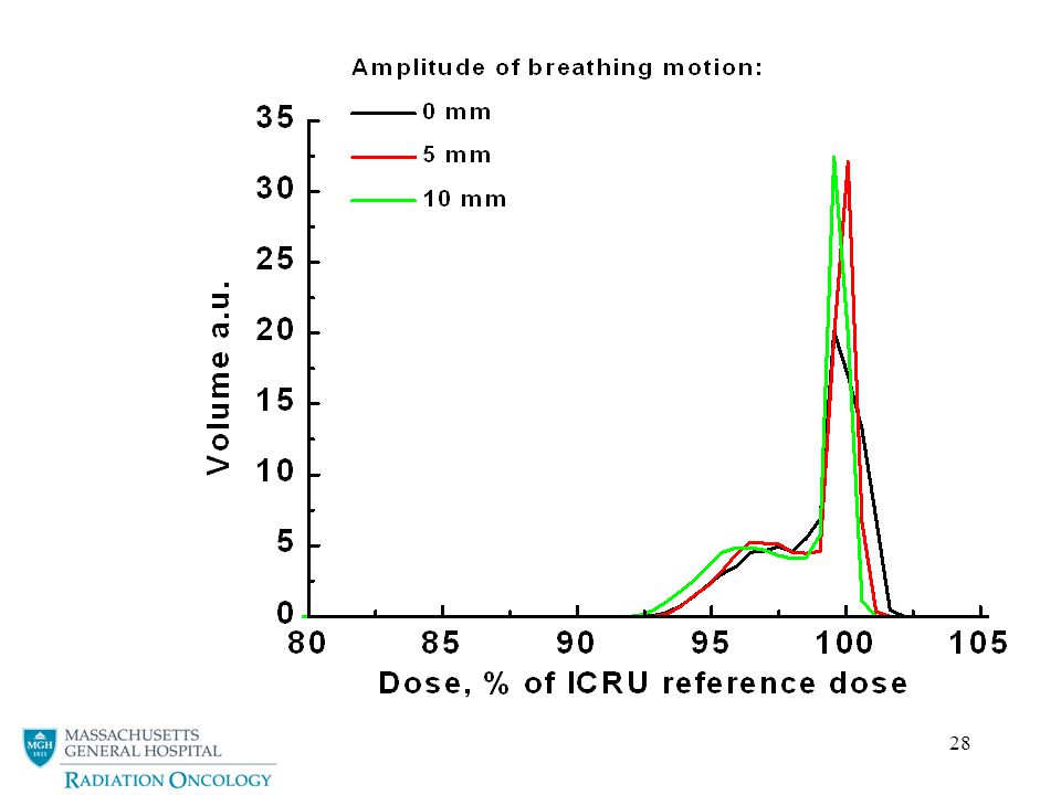
Effect of blurring on dose profile (conformal)
Only a limited shift in 95% isodose level This is for a photon profile in lung. The shift would be larger for a steeper profile (e.g. due to IMRT)
")
57
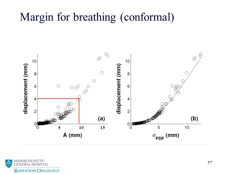
Margin for breathing (conformal)
5 10 15
58
Margin for breathing (IMRT)
Hypothetically Sharp Dose Distribution

59
Margin for breathing (IMRT)
5 10 15 IMRT

60
Breath hold

61
Control / stop patient breathing
Exhale position most reproducible Inhale position most beneficial for sparing lung tissue

62
Breath hold techniques
Voluntary breath hold Rosenzweig KE et al. The deep inspiration breath-hold technique in the treatment of inoperable non-small-cell lung cancer. Int J Radiat Oncol Biol Phys. 2000;48:81-7 Active Breathing Control (ABC) Wong JW et al. The use of active breathing control (ABC) to reduce margin for breathing motion. Int J Radiat Oncol Biol Phys. 1999;44:911-9 Abdominal press Negoro Y et al. The effectiveness of an immobilization device in conformal radiotherapy for lung tumor: reduction of respiratory tumor movement and evaluation of the daily setup accuracy. Int J Radiat Oncol Biol Phys. 2001;50:889-98 Usually, lung cancer patients have an impaired lung function and can not really hold there breath that easily.
 Wong JW et al. The use of active breathing control (ABC) to reduce margin for breathing motion. Int J Radiat Oncol Biol Phys. 1999;44: Abdominal press. Negoro Y et al. The effectiveness of an immobilization device in conformal radiotherapy for lung tumor: reduction of respiratory tumor movement and evaluation of the daily setup accuracy. Int J Radiat Oncol Biol Phys. 2001;50: Usually, lung cancer patients have an impaired lung function and can not really hold there breath that easily.")
63
Gating

64
Gated radiotherapy Gating window External or internal markers
Usually 20% duty cycle Some residual motion

65
Gating benefits and drawbacks
+ Less straining for patient than breath-hold Increased treatment time Internal markers Direct visualization of tumor (surroundings) Invasive procedure / side effects of surgery External markers Limited burden for patient Doubtful correlation between marker and tumor position Intra-fractional Inter-fractional - + - + -
 Invasive procedure / side effects of surgery. External markers. Limited burden for patient. Doubtful correlation between marker and tumor position. Intra-fractional. Inter-fractional")
66
Motion in charged particle therapy

67
T. Bortfeld

68
Range sensitivity Spherical tumor in lung Paralell opposed - photons
Single field - photons Single field - protons Displayed isodose levels: 50%, 80%, 95% and 100%

69
Range sensitivity Spherical tumor in lung Paralell opposed - photons
Single field - photons Single field - protons Displayed isodose levels: 50%, 80%, 95% and 100%

70
Range sensitivity Spherical tumor in lung Paralell opposed - photons
Single field - photons Single field - protons Displayed isodose levels: 50%, 80%, 95% and 100%

71
Dose-Volume Histogram (protons)
PTV (static) CTV GTV CTV-GTV
 CTV. GTV. CTV-GTV.")
72
SOBP Modulation Beam High-Density Structure Target Volume Critical
Range Compensator Body Surface

73
Passive scattering system
Aperture Range Compensator + = Lateral conformation Distal conformation

74
Smearing the range compensator
High-Density Structure Target Volume Beam Critical Structure Range Compensator Body Surface

75
Smearing the range compensator
High-Density Structure Target Volume Beam Critical Structure Range Compensator Body Surface

76
C D Smear Setup Error A B 10 C D
B 10 C D Displayed isodose levels: 50%, 80%, 95% and 100%

77
Motion management in particle therapy
Passive scattered particle therapy For setup errors and (possibly) breathing motion Lateral expansion of apertures Smearing of range compensators IMPT See, e.g., lecture “Optimization with motion and uncertainties”
 breathing motion. Lateral expansion of apertures. Smearing of range compensators. IMPT. See, e.g., lecture Optimization with motion and uncertainties")
78
Thank you for your attention

Similar presentations