Download presentation
Presentation is loading. Please wait.

1
http://www.nearingzero.nethttp://www.nearingzero.net (work030.jpg)
")
2
LEAD Tutors/Peer Instructors Needed! You can tutor or be a PLC peer instructor if you have at least a 3.6 GPA and get an “A” in the course you want to tutor. It looks good on your resume, pays well, and is fun! Contact me or go to http://lead.mst.edu/ to fill out the application form. http://lead.mst.edu/ application form

3
points earned average score (excluding the “free-only” scores)=35.4 (70.4%) End Material Test Grading
=35.4 (70.4%) End Material Test Grading")
4
average score (excluding the “free-only” scores)=27.8 (55.6%) points earned
=27.8 (55.6%) points earned")
5
Spring 2008 average score (excluding the “free-only” scores)=37.8 (75.6%) Other semester averages (excluding the “free-only” scores) Fall 2008 34.7 (69.4%)Spring 2009 39.0 (78%)Fall 2009 34.9 (69.8%) Spring 2010 36.1 (72.2%)Fall 2010 34.9 (69.8%)Spring 2011 31.6 (63.6%) Fall 2011 35.4 (70.8%)Spring 2012 36.9 (73.8%)Fall 2012 36.0 (72.0%) Spring 2013 39.1! (78.2%)Fall 2013 34.9 (69.8%)Spring 2014 33.4 (66.8%) Fall 2014 35.0 (70.0%)Spring 2015 (69.0%)
Fall (69.8%)Spring (66.8%) Fall (70.0%)Spring 2015 (69.0%).")
7
Remember, it’s the points that count! If you want to use the spreadsheet to forecast your grade, make sure… …there is an “8” in the EM column (column x)… …so you won’t be mis-led by a percent that seems to be above a grade cutoff when your actual points are below the cutoff. Checking the grades spreadsheet…grades spreadsheet I have “hidden” your midterm grade and percent columns, but you can see them if you “unhide” them.
… …so you won’t be mis-led by a percent that seems to be above a grade cutoff when your actual points are below the cutoff. Checking the grades spreadsheet…grades spreadsheet I have hidden your midterm grade and percent columns, but you can see them if you unhide them..")
8
Know the exam time! Find your room ahead of time! If at 12:30 on test day you are lost, go to 104 Physics and check the exam room schedule, then go to the appropriate room and take the exam there. Exam is from 12:30-2:30 pm! Physics 2135 Final Exam Rooms, Fall 2015: InstructorSectionsRoom Dr. HagenJ, R125 BCH Dr. HaleK, P120 BCH Dr. HorB, DG-31 EE Dr. KurterA, CSt. Pat’s Ballroom Dr. MadisonG, L204 McNutt Dr. ParrisM, Q103/104 Centennial Mr. UpshawN, HG-5 H/SS Dr. VojtaE, FSt. Pat’s Ballroom See notes on next slide for information about room locations. Special AccommodationsTesting Center

9
Physics 2135 Final Room Assignments, 12:30 PM, DEC 16 InstructorSectionsRoom Dr. HagenJ, R 125 BCH N ot your exam 1/2/3 room! Dr. HaleK, P 120 BCH Same room as for exams 1/2/3. Dr. HorB, D G-31 EE EE is Emerson Electric Hall (Electrical Engineering building). Dr. KurterA, C St. Pat’s St. Pat’s Ballroom in the Havener Center. Dr. MadisonG, L 204 McNutt Same room as for exams 1/2/3. Dr. ParrisM, Q 103/104 Centennial Classrooms in Centennial Hall with sliding partition in between them. Mr. UpshawN, H G-5 H/SS Same room as for exams 1/2/3. Dr. VojtaE, F St. Pat’s St. Pat’s Ballroom in the Havener Center.
. Dr. KurterA, C St. Pat’s St. Pat’s Ballroom in the Havener Center. Dr. MadisonG, L 204 McNutt Same room as for exams 1/2/3. Dr. ParrisM, Q 103/104 Centennial Classrooms in Centennial Hall with sliding partition in between them. Mr. UpshawN, H G-5 H/SS Same room as for exams 1/2/3. Dr. VojtaE, F St. Pat’s St. Pat’s Ballroom in the Havener Center..")
10
Today’s agenda: Thin Film Interference. Phase Change Due to Reflection. You must be able to determine whether or not a phase change occurs when a wave is reflected. Phase Change Due to Path Length Difference. You must be able to calculate the phase difference between waves reflecting of the “front” and “back” surfaces of a thin film. Thin Film Interference. You must be able to calculate thin film thicknesses for constructive or destructive interference. Examples. You must be able to solve problems similar to these examples.

11
y = A sin (kx - t)
")
12
Light undergoes a phase change of 180° ( radians) upon reflection from a medium that has a higher index of refraction than the one in which the wave is traveling. Applet.Applet Interference from Reflection Thin Film Interference: Phase Change Due to Reflection “string analogy” graphics from http://dev.physicslab.org/Document.aspx?doctype=3&filename=PhysicalOptics_ThinFilmInterference.xml

13
Crest (blue) is reflected as a trough (orange): phase change. Thin Film Interference: Phase Change Due to Reflection graphics from http://dev.physicslab.org/Document.aspx?doctype=3&filename=PhysicalOptics_ThinFilmInterference.xmlhttp://dev.physicslab.org/Document.aspx?doctype=3&filename=PhysicalOptics_ThinFilmInterference.xml (good source of self-study material!) n1n1 n1n1 n 2 > n 1 n 2 < n 1 Crest (blue) is reflected as a crest (orange): no phase change.
 n1n1 n1n1 n 2 > n 1 n 2 < n 1 Crest (blue) is reflected as a crest (orange): no phase change..")
14
Thin Film Interference: Phase Change Due to Reflection graphics from http://dev.physicslab.org/Document.aspx?doctype=3&filename=PhysicalOptics_ThinFilmInterference.xmlhttp://dev.physicslab.org/Document.aspx?doctype=3&filename=PhysicalOptics_ThinFilmInterference.xml (good source of self-study material!) The two cases overlaid: notice how the two reflected waves differ in phase by ½ of a wavelength.
 The two cases overlaid: notice how the two reflected waves differ in phase by ½ of a wavelength.")
15
Thin Film Interference: Phase Change Due to Reflection How to remember the phase change: “Low to high, change is .” (© 2001, D. M Sparlin)
.")
16
Today’s agenda: Thin Film Interference. Phase Change Due to Reflection. You must be able to determine whether or not a phase change occurs when a wave is reflected. Phase Change Due to Path Length Difference. You must be able to calculate the phase difference between waves reflecting of the “front” and “back” surfaces of a thin film. Thin Film Interference. You must be able to calculate thin film thicknesses for constructive or destructive interference. Examples. You must be able to solve problems similar to these examples.

17
Thin Film Interference: Effect of Path Length Difference Example: light of wavelength 600 nm in air is perpendicularly incident on a piece of glass 4.1 µm thick. The index of refraction of glass is 1.5. Some of the light is reflected off the “back” surface of the glass. How many light waves are contained along the path of this light through the glass? Air Glass t Air Light enters the glass… …passes through the glass and reflects off the “back” surface… …passes back through the glass… …and exits. Some probably reflects back off the front surface, but we are not talking about that light. Some probably passes through the second glass surface, but we are not talking about that light. Some probably reflects back into the glass, but we are not talking about that light.

18
Thin Film Interference: Path Length Difference How many “waves” can fit in the path of length 2t? How many light waves are contained along the path of this light through the glass? Air Glass t Air

19
Thin Film Interference: Path Length Difference The outgoing waves would differ in phase by ½ wavelength from the incoming waves… Are the outgoing waves in phase or out of phase with the incoming waves Air Glass t Air …except that you must also consider phase shift due to reflection (so we can’t give the answer just yet). Note: if you look down at the glass, your eye sees only the reflected waves; you will not see interference of the incident and reflected waves, so you are not being asked if interference between incident and reflected waves will take place.

20
Today’s agenda: Thin Film Interference. Phase Change Due to Reflection. You must be able to determine whether or not a phase change occurs when a wave is reflected. Phase Change Due to Path Length Difference. You must be able to calculate the phase difference between waves reflecting of the “front” and “back” surfaces of a thin film. Thin Film Interference. You must be able to calculate thin film thicknesses for constructive or destructive interference. Examples. You must be able to solve problems similar to these examples.

21
Thin film interference is caused by… Thin Film Interference …phase difference of reflected waves due to path length differences… …and phase difference of reflected waves due to reflection off a higher-n material. http://www.photographyblog.com/gallery/showphoto.php?photo=5545

22
No phase change Air Film t n Air < n Film Do the reflected rays and interfere destructively or constructively? Caution! The wavelength in the film is different than in air. 180° phase change Thin Film Interference, Including Reflection Ray undergoes a phase change on reflection. Ray does not undergo a phase change on reflection.. Dark lines in drawings are there to help you see the boundaries, and are not a separate medium. Ray has a phase change due to the path difference.

23
We will get destructive interference when the path difference is an integral number of wavelengths: Assume the incident light is nearly perpendicular to the film surface. No phase change Air Film t n Air < n Film 180° phase change The path length difference is approximately 2t. There is a 180 phase difference (½ of a wavelength) due to the first reflection. 180° phase change
 due to the first reflection. 180° phase change.")
24
We will get constructive interference when the path difference is a half-integral number of wavelengths: Assume the incident light is nearly perpendicular to the film surface. No phase change Air Film t n Air < n Film 180° phase change We get constructive interference when the path difference is film /2, 3 film /2, 5 film /2, etc.

25
No phase change Air Film t n Air < n Film 180° phase change You need to apply the reasoning used here in deriving them to each of your thin film interference problems. These are only true when the film is surrounded by a medium with lower index of refraction than the film! The equations below are not on your starting equation sheet.

26
No phase change Air Film t n Air < n Film 180° phase change These are valid when the light is incident almost perpendicular to the film: Caution! The incident ray in the diagram clearly does not qualify visually as “almost perpendicular.” That’s because the angle relative to the normal is exaggerated for viewing convenience.

27
No phase change Air Film t n Air < n Film 180° phase change Caution! For truly non-perpendicular incidence, you have to take into account the extra path length of the ray reflected at the air-film interface, as well as the extra path length inside the film because the path is not perpendicular to the surfaces.

28
Thin Film Interference Problem Solving Tips Identify the thin film causing the interference. Determine the phase difference due to reflection between the portion of the wave reflected at the upper surface and the portion reflected at the lower surface. Phase differences have two causes: (1) path differences and (2) phase changes upon reflection (low to high, change is ). When the total phase difference is an integer multiple of the wavelength (, 2, 3, etc.) the interference is constructive, and when it is a half-integer multiple of the wavelength ( /2, 3 /2, 5 /2, etc.) it is destructive. Determine the phase difference due to the path length difference (in the thin film).
 path differences and (2) phase changes upon reflection (low to high, change is ). When the total phase difference is an integer multiple of the wavelength (, 2, 3, etc.) the interference is constructive, and when it is a half-integer multiple of the wavelength ( /2, 3 /2, 5 /2, etc.) it is destructive. Determine the phase difference due to the path length difference (in the thin film)..")
29
Today’s agenda: Thin Film Interference. Phase Change Due to Reflection. You must be able to determine whether or not a phase change occurs when a wave is reflected. Phase Change Due to Path Length Difference. You must be able to calculate the phase difference between waves reflecting of the “front” and “back” surfaces of a thin film. Thin Film Interference. You must be able to calculate thin film thicknesses for constructive or destructive interference. Examples. You must be able to solve problems similar to these examples.

30
http://www.fas.harvard.edu/~scdiroff/lds/LightOptics/ThinFilmInterference/ThinFilmInterference04.jpg

31
http://en.wikipedia.org/wiki/File:Dieselrainbow.jpg

32
http://www.fas.harvard.edu/~scdiroff/lds/LightOptics/ThinFilmInterference/ThinFilmInterference02.jpg
33
http://www.tufts.edu/as/tampl/projects/micro_rs/theory.html#thinfilm

34
λ/2

35
Engineers create chameleon-like artificial 'skin' that shifts color on demand The chameleon reorganizes its nanocrystals to change colors

36
Example: a glass lens is coated on one side with a thin film of MgF 2 to reduce reflection from the lens surface. The index of refraction for MgF 2 is 1.38 and for glass is 1.50. What is the minimum thickness of MgF 2 that eliminates reflection of light of wavelength λ = 550 nm? Assume approximately perpendicular angle of incidence for the light. Both rays and experience a 180 phase shift on reflection so the total phase difference is due to the path difference of the two rays. Air MgF 2 t n= 1.38 n Air = 1.00 180° phase change 180° phase change glass, n g =1.50

37
The minimum thickness is for m=0. The reflected light is minimum when the two light rays meet the condition for destructive interference: the path length difference is a half-integral multiple of the light wavelength in MgF 2. Air MgF 2 t n= 1.38 n Air = 1.00 180° phase change 180° phase change glass, n g =1.50

38
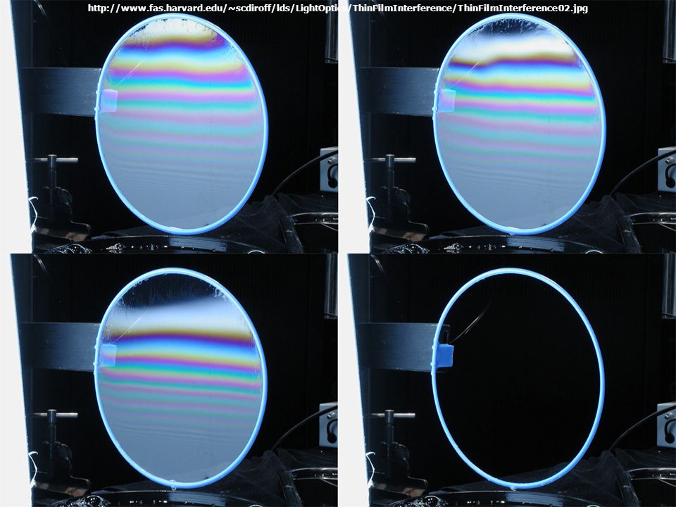
fringes Color pattern occurs because incident light is not monochromatic.

39
Example: two glass plates 10 cm long are in contact on one side and separated by a piece of paper 0.02 mm thick on the other side. What is the spacing between the interference fringes? Assume monochromatic light with a wavelength in air of λ = 500 nm incident perpendicular to the slides. Ray is not phase shifted on reflection. H t x L = 10 cm H = 2x10 -5 m For destructive interference The light that is reflected from the top and bottom of the very thin air wedge is responsible for the interference* *This reference explains why there is no visible interference due to the relatively thick glass plates themselves.This Ray is not phase shifted on reflection. Ray is shifted 180 on reflection.

40
H t x L = 10 cm H = 2x10 -5 m Successive dark fringes are separated by 1.25 mm. x is the distance from the contact point to where destructive interference takes place.

41
H t x L = 10 cm H = 2x10 -5 m Successive bright fringes occur for m+½ and (m+1)+½. For constructive interference

42
H t x L = 10 cm H = 2x10 -5 m Successive bright fringes are also separated by 1.25 mm. Successive bright fringes occur for m+½ and (m+1)+½.
+½..")
43
fringes Non-uniform fringe spacing occurs because “air wedge” is not triangular.

44
Example: suppose the glass plates have n g = 1.50 and the space between them contains water (n w = 1.33). What happens now? Ray is not phase shifted on reflection. Ray is shifted 180 on reflection. Both are the same as before. H t x L = 10 cm H = 2x10 -5 m For destructive interference But the path difference now occurs in water, where the light will have a wavelength Repeat the calculation, using water.

45
Successive dark fringes are separated by 0.94 mm. For destructive interference, we now have H t x L = 10 cm H = 2x10 -5 m

Similar presentations


 sine waves are nice>")


>")
