Download presentation
Presentation is loading. Please wait.

1
Introduction to Power Supply Design
Power your creations! Introduction to Power Supply Design IEEE Concordia Student Branch Marc-Alexandre Chan, Amit Desai 21 November 2015 Image: Seva Kovtoun, © 2015 IEEE Concordia. All Rights Reserved.

2
Legend: Figures licensing
[PD] Public domain [CC] Creative Commons [GFDL] GNU Free Doc. License [GPL] GNU Public License [O] Other. See source for licensing.

3
Why this workshop? Electronics need a power source!
Various wall wart supplies (left). A computer power supply (right). Fig. [PD] Marc-Alexandre Chan. Original.
. A computer power supply (right). Fig. [PD] Marc-Alexandre Chan. Original")
4
Why this workshop? Power supplies: You use them all the time…
But do you know how they work? 7805, LM317: magic linear voltage regulator Computer power supply, laptop/phone charger: magic switch-mode power supply Ideal voltage source: magic (Really. It doesn’t exist; we just imitate it to the extent necessary.)
")
5
What will we learn? Basic types of power supplies & converters
Choose the best kind for your project Design & build your own! Get a glimpse of safety & advanced concepts

6
Outline AC-DC converter: Using a power outlet for electronics
DC-DC: Linear voltage regulators Switched-mode converters: buck & boost Safety & advanced topologies Applications to real-world power supplies: What’s a serious power supply unit look like?

7
1 AC-to-DC conversion or using a power outlet for electronics

8
1 AC-DC Converter Wall outlet AC power Electronics DC power
How to make this work? 0V → 0V → Top: 110V 60Hz AC voltage from a wall outlet; Bottom: 12V DC from a car battery (bottom). [2] [1] [PD] JAK83 [2] [PD] Marc-Alexandre Chan. Original. Two NEMA 5-15 sockets [1]
. [2] [1] [PD] JAK83 [2] [PD] Marc-Alexandre Chan. Original. Two NEMA 5-15 sockets [1]")
9
AC-DC converter. [PD] Marc-Alexandre Chan.
Solution: Convert AC to DC (rectification) Parts: Transformer, rectifier, filter AC-DC converter. [PD] Marc-Alexandre Chan.
![AC-DC converter. [PD] Marc-Alexandre Chan.](http://slideplayer.com/slide/9144315/27/images/9/AC-DC+converter.+%5BPD%5D+Marc-Alexandre+Chan..jpg "Solution: Convert AC to DC (rectification) Parts: Transformer, rectifier, filter. AC-DC converter. [PD] Marc-Alexandre Chan")
10
1 AC-DC: Transformer “Transform” AC voltage
Step-up → voltage ↑ Step-down → voltage ↓ Does not work with DC Turns ratio 𝑁 𝑆 : 𝑁 𝑃 (of wires) Ideal: 𝑉 𝑠 = 𝑁 𝑆 𝑁 𝑃 𝑉 𝑃 Real: losses + frequency * Transforms AC voltage: increase or decrease it * Works ONLY with AC, relies on changing voltage + current (derivatives). * Side with more windings = higher voltage * Example: 1000 turns to 100 turns, 10V primary gives 1V secondary * Or 100 turns to 1000 turns, 10V primary gives 100V secondary * Reality: losses and frequency dependence (specific design) A small mains transformer (top) [1]; Basic transformer showing wire windings and electrical-to-magnetic energy conversion [2]. [1] [CC] ZngZng [2] [CC] BillC
 Ideal: 𝑉 𝑠 = 𝑁 𝑆 𝑁 𝑃 𝑉 𝑃. Real: losses + frequency. * Transforms AC voltage: increase or decrease it. * Works ONLY with AC, relies on changing voltage + current (derivatives). * Side with more windings = higher voltage. * Example: 1000 turns to 100 turns, 10V primary gives 1V secondary. * Or 100 turns to 1000 turns, 10V primary gives 100V secondary. * Reality: losses and frequency dependence (specific design) A small mains transformer (top) [1]; Basic transformer showing wire windings and electrical-to-magnetic energy conversion [2]. [1] [CC] ZngZng [2] [CC] BillC")
11
1 AC-DC Converter: Transformer
What is the role of the transformer? 120VAC (169V amplitude) too high for electronics! Step-down transformer: reduce 𝑉 to usable value Example: 120VAC to e.g. 9VAC Reminder: VAC is the RMS voltage = 𝑉 𝑎𝑚𝑝𝑙𝑖𝑡𝑢𝑑𝑒 2 So 9VAC is ≈12.7V amplitude
 too high for electronics! Step-down transformer: reduce 𝑉 to usable value. Example: 120VAC to e.g. 9VAC. Reminder: VAC is the RMS voltage = 𝑉 𝑎𝑚𝑝𝑙𝑖𝑡𝑢𝑑𝑒 2. So 9VAC is ≈12.7V amplitude")
12
1 AC-DC Converter: Rectifier
Input is AC: sine wave goes positive & negative To rectify = to make one-sided Output is only positive (sometimes only negative) Output is not DC yet… still “bouncing!” Most commonly uses diodes… let’s review! Voltage plots of (blue) an AC waveform and (orange) the rectified waveform [PD] Marc-Alexandre Chan. Original.
 Output is not DC yet… still bouncing! Most commonly uses diodes… let’s review! Voltage plots of (blue) an AC waveform and. (orange) the rectified waveform. [PD] Marc-Alexandre Chan. Original")
13
1 AC-DC Converter: Diodes
One-way current gate Ideal: a one-way “wire” Non-ideal: Constant voltage drop VD when passing forward current Reverse leakage: small reverse currents possible (μA) Different diode types: silicon, germanium, Schottky… Better non-ideal model: exponential 𝑉 𝐷 = 𝐼 𝑆 𝑒 𝑉 𝐷 𝑉 𝑇 −1 Voltage increases a bit when current increases Diode schematic symbol. Current can flow A→K, but not K→A. 𝑉 𝑇 ≈26𝑚𝑉 at 300K 𝑉 𝑇 = 𝑘𝑇 𝑞 , k = Boltzmann const, q = electron charge
 Different diode types: silicon, germanium, Schottky… Better non-ideal model: exponential. 𝑉 𝐷 = 𝐼 𝑆 𝑒 𝑉 𝐷 𝑉 𝑇 −1. Voltage increases a bit when current increases. Diode schematic symbol. Current can flow A→K, but not K→A. 𝑉 𝑇 ≈26𝑚𝑉 at 300K. 𝑉 𝑇 = 𝑘𝑇 𝑞 , k = Boltzmann const, q = electron charge")
14
1 AC-DC Converter: Diodes
Anode Cathode Diodes, oriented for current flow left to right. A line (black or silver) marks the cathode. a) DO-35 glass package [1]. b) DO-41 package [2]. c) Schematic symbol. [1] [CC] Vonvon. [2] [CC] Vonvon.
 marks the cathode. a) DO-35 glass package [1]. b) DO-41 package [2]. c) Schematic symbol. [1] [CC] Vonvon. [2] [CC] Vonvon")
15
1 AC-DC Converter: Rectifier
Half-wave rectifier: one diode Passes current one way only = no more negative voltage “Blocks” half the sine wave: less available power! Demo TODO: Add sine graph Half-wave rectifier a) circuit; b) simulation plot of the output voltage. [PD] Marc-Alexandre Chan. Original.
 circuit; b) simulation plot of the output voltage. [PD] Marc-Alexandre Chan. Original")
16
1 AC-DC Converter: Rectifier
Full-wave rectifier: four diodes Diodes force current into the + node and out of the – node for the sine wave (positive and negative) Absolute value function Diode directions Full-wave rectifier a) circuit; b) simulation plot of the output voltage. [PD] Marc-Alexandre Chan. Original.
 Absolute value function. Diode directions. Full-wave rectifier a) circuit; b) simulation plot of the output voltage. [PD] Marc-Alexandre Chan. Original")
17
1 AC-DC Converter: Filter
Rectifier output is all positive … but “bumpy”! Use a filter Big capacitor to store charge Helps V stay up by providing I in “valleys” of the “bumps” Full-wave rectifier with filter a) circuit; b) simulation plot of the output voltage. [PD] Marc-Alexandre Chan. Original.
 circuit; b) simulation plot of the output voltage. [PD] Marc-Alexandre Chan. Original")
18
1 AC-DC Converter: Ripple
Even with filter, some “bumps”: called ripple Depends on capacitor size + load current Need impractically big cap for high current + low ripple Design: Given 𝑉 𝑚𝑎𝑥 ,𝑓, choose 𝑉 𝑟 , 𝑅 𝐿(𝑚𝑖𝑛) , and find 𝐶 needed Average (DC) * Ripple because the capacitor has to discharge in order to compensate for the big “bumps” V drops * For very small ripple (< 100s mV) and high currents (> 100mA), cap becomes huge * Real power supplies: 470μF to 4700μF or so (or higher → very high current) * Big & expensive: for small electronics, can we do better? (will see later) Ripple 𝑉 𝑟 = 𝑉 𝑚𝑎𝑥 1− 𝑒 − 1 2𝑓 ∗ 1 𝑅 𝐿 𝐶 for R load 𝑉 𝑟 = 𝐼 2𝑓𝐶 for constant I load 𝑓= AC frequency (60Hz here)
 , and find 𝐶 needed. Average (DC) * Ripple because the capacitor has to discharge in order to compensate for the big bumps V drops. * For very small ripple (< 100s mV) and high currents (> 100mA), cap becomes huge. * Real power supplies: 470μF to 4700μF or so (or higher → very high current) * Big & expensive: for small electronics, can we do better (will see later) Ripple. 𝑉 𝑟 = 𝑉 𝑚𝑎𝑥 1− 𝑒 − 1 2𝑓 ∗ 1 𝑅 𝐿 𝐶 for R load. 𝑉 𝑟 = 𝐼 2𝑓𝐶 for constant I load. 𝑓= AC frequency (60Hz here)")
19
DESIGN: Full-Bridge Rectifier

20
1 DESIGN: Rectifier Design Procedure
Choose V 𝑖𝑛 (AC), 𝑉 𝑟𝑖𝑝𝑝𝑙𝑒,𝑚𝑎𝑥 , 𝐼 𝑜𝑢𝑡,𝑚𝑎𝑥 Choose diode and output capacitor Thermal analysis: avoid going poof! Done!
, 𝑉 𝑟𝑖𝑝𝑝𝑙𝑒,𝑚𝑎𝑥 , 𝐼 𝑜𝑢𝑡,𝑚𝑎𝑥. Choose diode and output capacitor. Thermal analysis: avoid going poof! Done!")
21
1 DESIGN Rectifier: Specifications
Let’s choose 𝑉 𝑖𝑛 =9𝑉 (AC rms) Because that’s the transformer we have for now! 𝑉 𝑜𝑢𝑡 ≤9 2 =12.7𝑉 DC after rectification Depends on output capacitor / amount of ripple Peak of output voltage “bumps” is 12.7V, average is less 𝑉 𝑟𝑖𝑝𝑝𝑙𝑒,𝑚𝑎𝑥 =1.0𝑉 This is big, but we’re learning regulators next! 𝐼 𝑜𝑢𝑡,𝑚𝑎𝑥 =100𝑚𝐴 We will also look at 𝐼 𝑜𝑢𝑡 =25𝑚𝐴 to see what happens. Transformer: generally good to choose peak voltage close to highest target voltage, but still higher (diode drop + regulator drop…)
 Because that’s the transformer we have for now! 𝑉 𝑜𝑢𝑡 ≤9 2 =12.7𝑉 DC after rectification. Depends on output capacitor / amount of ripple. Peak of output voltage bumps is 12.7V, average is less. 𝑉 𝑟𝑖𝑝𝑝𝑙𝑒,𝑚𝑎𝑥 =1.0𝑉. This is big, but we’re learning regulators next! 𝐼 𝑜𝑢𝑡,𝑚𝑎𝑥 =100𝑚𝐴. We will also look at 𝐼 𝑜𝑢𝑡 =25𝑚𝐴 to see what happens. Transformer: generally good to choose peak voltage close to highest target voltage, but still higher (diode drop + regulator drop…)")
22
1 DESIGN Rectifier: Diode
Diode choice: 1N4001 rectifier diode (1N4002 to 1N4007) 𝑉 𝐷 =0.75𝑉 at 100mA (from datasheet I-V curve) Max reverse voltage, forward current, temperature… Schottky performs better but less efficient (reverse leakage). Output capacitor Ripple equation (const current): 𝑉 𝑟 = 𝐼 2𝑓𝐶 𝑉 𝑜𝑢𝑡,𝑚𝑎𝑥 ≈ 𝑉 𝑖𝑛,𝑝𝑒𝑎𝑘 −2 𝑉 𝐷 =12.7−1.5=11.2𝑉 (ripple peak) 𝐶= 𝐼 2𝑓 𝑉 𝑟 =833𝜇𝐹 → let’s go for 1000μF For 25mA, 𝐶=208𝜇𝐹 → go for 220μF Load: Use resistor to simulate circuit to power. At 11.2V, 100mA → ≈100Ω, 25mA → ≈470Ω (closest common Rs) * Diode: * Explain that 1N4002…7 can block a bigger reverse voltage without breaking down
 𝑉 𝐷 =0.75𝑉 at 100mA (from datasheet I-V curve) Max reverse voltage, forward current, temperature… Schottky performs better but less efficient (reverse leakage). Output capacitor. Ripple equation (const current): 𝑉 𝑟 = 𝐼 2𝑓𝐶. 𝑉 𝑜𝑢𝑡,𝑚𝑎𝑥 ≈ 𝑉 𝑖𝑛,𝑝𝑒𝑎𝑘 −2 𝑉 𝐷 =12.7−1.5=11.2𝑉 (ripple peak) 𝐶= 𝐼 2𝑓 𝑉 𝑟 =833𝜇𝐹 → let’s go for 1000μF. For 25mA, 𝐶=208𝜇𝐹 → go for 220μF. Load: Use resistor to simulate circuit to power. At 11.2V, 100mA → ≈100Ω, 25mA → ≈470Ω (closest common Rs) * Diode: * Explain that 1N4002…7 can block a bigger reverse voltage without breaking down")
23
1 DESIGN Rectifier: Diode
* Can see reverse voltage (peak, RMS), max DC and peak current, forward voltage, reverse leakage… 1N4001 datasheet excerpt: absolute maximum values. [O] Diodes, Inc. Fair use (educational).
, max DC and peak current, forward voltage, reverse leakage… 1N4001 datasheet excerpt: absolute maximum values. [O] Diodes, Inc. Fair use (educational)")
24
1 DESIGN Rectifier: Diode
* Voltages changes depending on current. * 100mA = 0.75V * 1.0A = 0.9V. * Graphs can be more informative than tables (tables give you “typical” or min-max values for some conditions) 1N4001 datasheet excerpt: Voltage drop vs. forward current (axes usually switched). [O] Diodes, Inc. Fair use (educational).
 1N4001 datasheet excerpt: Voltage drop vs. forward current (axes usually switched). [O] Diodes, Inc. Fair use (educational)")
25
1 DESIGN Rectifier: Thermal design
Heat flow circuit model Voltage = temperature(oC) Current = heat output (W) Thermal capacitance & resistance Worst case (long-term): DC steady-state So ignore capacitors Get 𝜃 𝐽𝐴 and max temp. from datasheet 𝑇 𝑗 = 𝑃 𝑗 ∗ 𝜃 𝐽𝐴 + 𝑇 𝑎𝑚𝑏 = 𝑉 𝐷 𝐼 𝐷(𝑚𝑎𝑥) 𝜃 𝐽𝐴 + 𝑇 𝑎𝑚𝑏 =0.75𝑉∗0.1𝐴∗100 °𝐶 𝑊 +27°𝐶 𝑇 𝑗 =34.5°𝐶 Max temp is 150°𝐶 → more than OK * Look at temperature of components (approximate / very rough) * Make sure no fire / damaged parts / magic smoke * Decide if we need heatsinks / bigger heatsinks * Does not predict temperature of too-thin wires or bad connections - breadboard * Heat output = P = VI of resistive elements (V ACROSS the resistor, not of the power supply or one of the nodes!) * Thermal capacitance & resistance: use example of two metal blocks connected by a metal rod * Worst case (long-term): * DC steady-state * Ignore capacitors at DC * Ground = ambient temperature
 Current = heat output (W) Thermal capacitance & resistance. Worst case (long-term): DC steady-state. So ignore capacitors. Get 𝜃 𝐽𝐴 and max temp. from datasheet. 𝑇 𝑗 = 𝑃 𝑗 ∗ 𝜃 𝐽𝐴 + 𝑇 𝑎𝑚𝑏. = 𝑉 𝐷 𝐼 𝐷(𝑚𝑎𝑥) 𝜃 𝐽𝐴 + 𝑇 𝑎𝑚𝑏. =0.75𝑉∗0.1𝐴∗100 °𝐶 𝑊 +27°𝐶. 𝑇 𝑗 =34.5°𝐶. Max temp is 150°𝐶. → more than OK. * Look at temperature of components (approximate / very rough) * Make sure no fire / damaged parts / magic smoke. * Decide if we need heatsinks / bigger heatsinks. * Does not predict temperature of too-thin wires or bad connections - breadboard. * Heat output = P = VI of resistive elements (V ACROSS the resistor, not of the power supply or one of the nodes!) * Thermal capacitance & resistance: use example of two metal blocks connected by a metal rod. * Worst case (long-term): * DC steady-state. * Ignore capacitors at DC. * Ground = ambient temperature")
26
1 DESIGN Rectifier: Thermal design
Meant to be a quick & dirty analysis Worst case scenario: is it well below the max temp? Do we need to add heatsinking or cooling? Forced air (e.g. fan) = lower temperatures Should be measured in lab if a concern More info:
 = lower temperatures. Should be measured in lab if a concern. More info:")
27
1 DESIGN Rectifier: Done!
𝑉 𝑖𝑛 =9𝑉𝐴𝐶, 𝑉 𝑜𝑢𝑡 ≈11.4𝑉 D1-4 = 1N4001, C = 1000μF or 220μF 𝑅 𝐿 = 100Ω or 470Ω 𝑉 𝑟𝑖𝑝𝑝𝑙𝑒,𝑚𝑎𝑥 =1.0𝑉 @ 𝐼 𝑚𝑎𝑥 =100𝑚𝐴

28
Let’s get building!

29
But first… what’s this breadboard thing?
Breadboard: Make connections without a mess! No solder, no PCB design, no chemicals Good for quick low-frequency prototyping Lots of capacitance everywhere! Next slide: pattern of connected holes (green) Power rails may or may not be connected: look at line! Tip: insert leads straight downward with even, steady pressure, one at a time. Otherwise your leads will bend or break!
 Power rails may or may not be connected: look at line! Tip: insert leads straight downward with even, steady pressure, one at a time. Otherwise your leads will bend or break!")
30
But first… what’s this breadboard thing?
Breadboard: Make connections without a mess! No solder, no PCB design, no chemicals Good for quick low-frequency prototyping Lots of capacitance everywhere! Next slide: pattern of connected holes (green) Power rails may or may not be connected: look at line! Tip: insert leads straight downward with even, steady pressure, one at a time. Otherwise your leads will bend or break! Fig. 5 Breadboard connections (green). Power rails (top and bottom) are not connected on this breadboard, but may be on other models; the red and blue lines usually shows this. (Source: Nevit Dilmen, Wikimedia Commons)
 Power rails may or may not be connected: look at line! Tip: insert leads straight downward with even, steady pressure, one at a time. Otherwise your leads will bend or break! Fig. 5 Breadboard connections (green). Power rails (top and bottom) are not connected on this breadboard, but may be on other models; the red and blue lines usually shows this. (Source: Nevit Dilmen, Wikimedia Commons)")
31
The line marks the direction (symbol and real parts shown).
Diode direction Black line on glass body Silver line on black body The line marks the direction (symbol and real parts shown). Figures shown previously.
. Figures shown previously")
32
“Can” capacitors: polarity!
Some capacitors are polarized. We will only use these ones; pay attention to the “minus” mark. These capacitors can explode if backwards or overvolted. [PD] Elcap. Elcaps.jpg

33
Barrel connector X Connect the two circled terminals. Polarity does not matter, as the source is isolated AC. Careful not to connect two pins into connected holes on the breadboard—short circuit risk! [O] CUI, Inc. Educational use.

34
IMPORTANT: Safety tips!
Never work on a circuit while plugged in! Unplug before touching/moving components. Risk of accidental short circuit, shock at high voltage, etc. Work with one hand in your pocket/lap. Low voltage → low risk. But good habit for all power electronics. Will save your life with low-impedance high-V supplies. Be careful about short circuiting supplies. Supplies can provide a LOT of current: smoke, fire, etc. This goes for whole circuit, but supplies most dangerous. Only connect oscilloscope ground to circuit ground. Details aside, this avoids mistakes that can damage oscilloscope.

35
1 MAKE: AC-DC Converter The resistor simulates the circuit you want to power Try different 𝑅 𝐿 and 𝐶 (R↓ or I↑ or C↓ → ripple ↑) C = 1000μF or 220μF 𝑅 𝐿 = 470Ω or 100Ω See the Handout

36
Break time! Want a snack? Wash your hands.
Lead-based solder at the lab.

37
Linear DC-DC Regulator
2 Linear DC-DC Regulator Image: LM2940L-5.0 LDO die photograph. Source: [CC] ZeptoBars,

38
2 Motivation Electronics want a DC voltage
AC-DC converter has ripple noise Causes signal noise, errors in digital data, IC resetting Small ripple → huge, expensive capacitor Other sources of problems AC voltage maybe not constant (noise, surge/sag, etc.) An existing DC supply is at wrong voltage or too noisy Can we solve this any other way?
 An existing DC supply is at wrong voltage or too noisy. Can we solve this any other way")
39
2 Regulators Voltage regulator: Keeps output voltage constant
Uses a control system to read & adjust output Input-output assumptions don’t affect accuracy ELEC372 + ELEC level controls courses Reacts to change in 𝑉 𝑖𝑛 (line regulation) Reacts to change in 𝐼 𝑜𝑢𝑡 (= 𝑅 𝐿 ) (load regulation)
 Reacts to change in 𝐼 𝑜𝑢𝑡 (= 𝑅 𝐿 ) (load regulation)")
40
2 Linear Voltage Regulator
Strategy: Transistor as Variable Resistor Adjust resistance to keep output voltage constant Output voltage function of 𝑉 𝑖𝑛 and 𝐼 𝑜𝑢𝑡 Can only reduce voltage A 7805 (top) and LM137 TO-220 package. This package is often used for three-pin voltage regulators and high-current transistors. [CC] John Dalton 220_Package_Four_Different_Projections.jpg
 and LM137 TO-220 package. This package is often used for three-pin voltage regulators and high-current transistors. [CC] John Dalton 220_Package_Four_Different_Projections.jpg")
41
2 Linear Voltage Regulator
Advantages Cheap, simple Very good regulation (low output noise) Disadvantages: Inefficient (<60%): wastes extra energy as heat! They get hot! Proportional to voltage drop and current: 𝑃 𝑑𝑖𝑠𝑠 = 𝑉 𝑑𝑟𝑜𝑝 𝐼 𝑜𝑢𝑡
 Disadvantages: Inefficient (<60%): wastes extra energy as heat! They get hot! Proportional to voltage drop and current: 𝑃 𝑑𝑖𝑠𝑠 = 𝑉 𝑑𝑟𝑜𝑝 𝐼 𝑜𝑢𝑡")
42
DESIGN: Linear regulator

43
2 DESIGN: Linear Regulator
Design Procedure Choose V 𝑖𝑛,𝑚𝑖𝑛 , 𝑉 𝑜𝑢𝑡 , 𝐼 𝑜𝑢𝑡,𝑚𝑎𝑥 Choose a suitable linear regulator chip Choose capacitors Thermal analysis: avoid going poof! Done!

44
2 DESIGN Linear: 2 Specifications
Assume we need to power something with 5V 𝑉 𝑜𝑢𝑡 =5𝑉 Assume we have a ≈10 to 13VDC supply available 𝑉 𝑖𝑛,𝑚𝑖𝑛 =10𝑉 Assume our circuits will not use more than 80mA To be safe, let’s add a 25% overhead 𝐼 𝑜𝑢𝑡,𝑚𝑎𝑥 =100𝑚𝐴 From datasheet: max current 1A → 100mA is OK But check temperature later too!

45
2 DESIGN Linear: 2 Choose a Chip
Common/”classic” chips 78xx family (e.g = 5V) LM317 (adjustable output voltage) Let’s choose the 7805 because fixed 5V is OK Minimum voltage drop (“dropout”) 𝑉 𝑖𝑛 − 𝑉 𝑜𝑢𝑡 has to be bigger than minimum dropout e.g. 7805: 𝑉 𝑑𝑟𝑜𝑝,𝑚𝑖𝑛 = 2V, 𝑉 𝑜𝑢𝑡 = 5V, so 𝑉 𝑖𝑛,𝑚𝑖𝑛 = 7V We said 𝑉 𝑖𝑛,𝑚𝑖𝑛 for our supply is 10V, so this is OK
 LM317 (adjustable output voltage) Let’s choose the 7805 because fixed 5V is OK. Minimum voltage drop ( dropout ) 𝑉 𝑖𝑛 − 𝑉 𝑜𝑢𝑡 has to be bigger than minimum dropout. e.g. 7805: 𝑉 𝑑𝑟𝑜𝑝,𝑚𝑖𝑛 = 2V, 𝑉 𝑜𝑢𝑡 = 5V, so 𝑉 𝑖𝑛,𝑚𝑖𝑛 = 7V. We said 𝑉 𝑖𝑛,𝑚𝑖𝑛 for our supply is 10V, so this is OK")
46
Aside: On new regulator chips
Newer chips: low-dropout regulators (LDO) Dropout less than 500mV possible Smaller 𝑉 𝑖𝑛 − 𝑉 𝑜𝑢𝑡 (actual one, not the minimum) = more efficient & less heat Look at this if we need 𝑉 𝑜𝑢𝑡 closer to 𝑉 𝑖𝑛
 Dropout less than 500mV possible. Smaller 𝑉 𝑖𝑛 − 𝑉 𝑜𝑢𝑡 (actual one, not the minimum) = more efficient & less heat. Look at this if we need 𝑉 𝑜𝑢𝑡 closer to 𝑉 𝑖𝑛")
47
2 DESIGN Linear: 2 Choose a Chip
LM317: Output V is set by R1, R2 voltage divider C1 filters any input noise C2 filters noise caused by load (when circuit current changes over time) * Why capacitors? They don’t seem useful at DC, right? * C1/Cin filters input noise * C2/Cout filters noise on the output caused by the load * Load regulation: the chip is good at dealing with slow (DC) changes * Load regulation: fast/sudden changes are better dealt with by capacitor * Load current can change over time: for example, digital circuits switching * For filtering RF noise, can put another small Cout (depending on frequency) in parallel * Remember that caps have series resistance + inductance: they have a max freq (and get worse at higher freq) * So Cparallel = C1+C2 is wrong for real caps: they will each act like good capacitors at diff frequencies Typical circuit applications for a) 78xx [1]; b) LM317 [2]. [1] [O] LM7805 Datasheet (Fairchild Semiconductor). Educational use. [2] [O] LM317 Datasheet (Texas Instruments). Educational use.
 * Why capacitors They don’t seem useful at DC, right * C1/Cin filters input noise. * C2/Cout filters noise on the output caused by the load. * Load regulation: the chip is good at dealing with slow (DC) changes. * Load regulation: fast/sudden changes are better dealt with by capacitor. * Load current can change over time: for example, digital circuits switching. * For filtering RF noise, can put another small Cout (depending on frequency) in parallel. * Remember that caps have series resistance + inductance: they have a max freq (and get worse at higher freq) * So Cparallel = C1+C2 is wrong for real caps: they will each act like good capacitors at diff frequencies. Typical circuit applications for a) 78xx [1]; b) LM317 [2]. [1] [O] LM7805 Datasheet (Fairchild Semiconductor). Educational use. [2] [O] LM317 Datasheet (Texas Instruments). Educational use")
48
2 DESIGN Linear: 3 Capacitors
Input capacitor With AC-DC converter, filter cap is OK Except if AC-DC and linear regulator far away (a few cm) Generally, with “good” DC supply, 0.1–10.0μF filter noise due to wire impedance/RF noise Start with a value, and increase if needed Also good to use datasheet or application note example circuits (see last slide)
 Generally, with good DC supply, 0.1–10.0μF. filter noise due to wire impedance/RF noise. Start with a value, and increase if needed. Also good to use datasheet or application note example circuits (see last slide)")
49
2 DESIGN Linear: 3 Capacitors
Output capacitor: general rule μF Chip’s datasheet is a good place to start: 0.1μF Filters noise and current transients If sudden Δ𝐼 → helps in time before chip can react Big cap = slow but filters big Δ𝐼; small = fast, filt small Δ𝐼 Simulation DEMO later Change capacitor when needed (check w/scope) Big changes AND fast? High-frequency noise? Two different caps in parallel! Guideline: 2 decades apart (Capacitors have seris inductance, so not C eq = 𝐶 1 + 𝐶 2 )
 Big changes AND fast High-frequency noise Two different caps in parallel! Guideline: 2 decades apart. (Capacitors have seris inductance, so not C eq = 𝐶 1 + 𝐶 2 )")
50
2 DESIGN Linear: 3 Thermal
Voltage drop 𝑉 𝐼𝑁 =12𝑉 (max) 𝑉 𝑂𝑈𝑇 =5𝑉 𝑉 𝑑𝑟𝑜𝑝 =12−5=7𝑉 Current output 𝐼 𝑜𝑢𝑡 =100𝑚𝐴 (max) Power 𝑃=𝑉𝐼=7∗0.100=0.7𝑊 𝑇 𝑗 = 𝑃 𝑗 ∗ 𝜃 𝐽𝐴 + 𝑇 𝑎𝑚𝑏 = 𝑉 𝑑𝑟𝑜𝑝 𝐼 (𝑚𝑎𝑥) 𝜃 𝐽𝐴 + 𝑇 𝑎𝑚𝑏 =7𝑉∗0.1𝐴∗65 °𝐶 𝑊 +27°𝐶 𝑇 𝑗 =72.5°𝐶 Max temp is 125°𝐶 → OK
 𝑉 𝑂𝑈𝑇 =5𝑉. 𝑉 𝑑𝑟𝑜𝑝 =12−5=7𝑉. Current output. 𝐼 𝑜𝑢𝑡 =100𝑚𝐴 (max) Power. 𝑃=𝑉𝐼=7∗0.100=0.7𝑊. 𝑇 𝑗 = 𝑃 𝑗 ∗ 𝜃 𝐽𝐴 + 𝑇 𝑎𝑚𝑏. = 𝑉 𝑑𝑟𝑜𝑝 𝐼 (𝑚𝑎𝑥) 𝜃 𝐽𝐴 + 𝑇 𝑎𝑚𝑏. =7𝑉∗0.1𝐴∗65 °𝐶 𝑊 +27°𝐶. 𝑇 𝑗 =72.5°𝐶. Max temp is 125°𝐶 → OK")
51
2 DESIGN Linear: 3 Thermal
If 𝑇 𝑗 too high? Add heatsink? Add fan? Heatsink: similar model 𝜃 𝐽𝐶 : from chip datasheet 𝜃 𝐶𝐻 : from thermal paste datasheet (if used) or heatsink datasheet or best guess 𝜃 𝐻𝑆 : from heatsink datasheet or best guess * Go through each element one by one and explain it and where to find it (don’t really read the text on the side)
 or heatsink datasheet or best guess. 𝜃 𝐻𝑆 : from heatsink datasheet or best guess. * Go through each element one by one and explain it and where to find it (don’t really read the text on the side)")
52
MAKE: Linear regulator!
53
But first: 7805 Pinout Pinout for 78xx family in TO-220 package. Pins are numbered 1-3 from left to right in this diagram. [O] LM78xx datasheet, Fairchild Semiconductor. Educational use.

54
2 MAKE: Linear regulator!
See your handout

55
2 DEMO: Linear regulator
Fig. 19 Linear voltage regulator simulation circuit. Rfb and Cfb simulate a non-ideal amplifier response. At the beginning of the simulation, the power turns on and starts powering the 500Ω load; then, at 10μs, the load current suddenly increases (≈10Ω).
")
56
2 DEMO: Linear regulator
Fig. 20 Linear voltage regulator simulated output voltage. This shows the turn-on response and load regulation (load increase at 10μs).
")
57
2 DEMO: Linear regulator
Line regulation Input voltage down to 7V → output still 5V. Minimum dropout Below 7V input (2V dropout), loss of good line regulation. Load regulation With different currents, voltage stays close to target.
, loss of good line regulation. Load regulation. With different currents, voltage stays close to target")
58
(Reminder: wash hands.)
Break time! Stretch your legs. Sit back and relax. Ask questions. (Reminder: wash hands.)
")
59
3 Switching regulators Fundamentals: Buck & Boost converter 2015-11-21
Image: XT PC Power Supply. Source: [CC] Hans Haaser,

60
3 Switching regulators Linear voltage regulators are inefficient
Reduce voltage by dissipating extra power as heat What if we switch power on & off then filter it? Switches are theoretically 100% efficient Reminder: 𝑃 𝑠𝑤 = 𝑉 𝑠𝑤 𝐼 𝑠𝑤 When switch off, 𝐼 𝑠𝑤 =0 (open circuit) When switch on, 𝑉 𝑠𝑤 =0 (short circuit) Reality: leakage, series R, switching loss, controller needs power…
 When switch on, 𝑉 𝑠𝑤 =0 (short circuit) Reality: leakage, series R, switching loss, controller needs power…")
61
3 Switching regulators Example: Computer power supply unit
300 to 1000W A similar linear supply is: Very hot, very heavy Huge heatsink, xformer, fans And you thought your gaming rig heats up the room? A computer power supply. [PD] Marc-Alexandre Chan. Original.

62
3 Switching regulators Example: phone charger Not old DC wall warts
Tiny and lightweight Linear would be bigger, heavier and need cooling! Not old DC wall warts Heavy, blocky thing Transformer, rectifier, filter Not a switching supply Various DC wall warts. Top left is a mains-transformer-based supply. The remainder are switch-mode supplies. [PD] Marc-Alexandre Chan. Original.

63
3 Switching regulators Advantages Disadvantages
Small, lightweight and efficient (≥90% possible) Skip the transformer: use rectified 120VAC directly (not here, too dangerous w/o training!) Need isolation? High frequency = smaller transformer! Disadvantages More complex to design Requires a minimum output load Switching noise on the output (bad for precision circuits!) EMI emissions
 Skip the transformer: use rectified 120VAC directly (not here, too dangerous w/o training!) Need isolation High frequency = smaller transformer! Disadvantages. More complex to design. Requires a minimum output load. Switching noise on the output (bad for precision circuits!) EMI emissions")
64
3 Switching: Buck converter
Simplest switching DC-DC converter Decreases DC voltage Principle: turn input voltage on and off quickly Output voltage = take the average output over time Use PWM or PFM to change the average output voltage Use a control system to get a desired output voltage Use filtering to take the average (LC filter)
")
65
3 Switching: Buck converter
10% average 50% average 90% average PWM waveform (blue) and average voltage (orange), various duty cycles. If, for example, the input is 12V, the bottom waveform has a 12*0.9 = 10.8V average. [O] Nathaly Arraiz Matute. Microprocessors Tutorial 2: Arduino Robotics [slideshow]. IEEE Concordia, 10 October 2013.
 and average voltage (orange), various duty cycles. If, for example, the input is 12V, the bottom waveform has a 12*0.9 = 10.8V average. [O] Nathaly Arraiz Matute. Microprocessors Tutorial 2: Arduino Robotics [slideshow]. IEEE Concordia, 10 October")
66
3 Switching: Buck converter
VPWM VOUT VIN A theoretical buck converter circuit. The switch is turned on and off electronically by a controller. VPWM is filtered by the inductor, which stores energy when switch is on and releases it as current when switch is off. The diode + inductor ensure that VPWM is connected to ground when the switch opens. [PD]

67
3 Switching: Buck converter
Minimum load current is required Inductor must have “continuous current” (= never 0) Otherwise you don’t get PWM waveform! Hard to predict! How to lower the minimum current? Higher frequency, same inductor Less switch off time But more switching losses → lower efficiency Same frequency, bigger inductor Inductor holds more energy to release during switch off time But bigger, heavier & more expensive
 Otherwise you don’t get PWM waveform! Hard to predict! How to lower the minimum current Higher frequency, same inductor. Less switch off time. But more switching losses → lower efficiency. Same frequency, bigger inductor. Inductor holds more energy to release during switch off time. But bigger, heavier & more expensive")
68
3 Switching: Buck converter
If less than minimum load current Good controller: works but less effective/efficient Bad/no controller: 𝑉 𝑜𝑢𝑡 can go up to 𝑉 𝑖𝑛 & cause damage! Reason #104 not to buy cheap knockoff phone chargers How to ensure voltage is regulated? Put a permanent resistor: always minimum current Or put a “smart” load that turns on only when needed Wastes power! (→ Why to unplug your phone charger!)
")
69
3 Switching: Transistors
But wait! How do we make an electronic switch? Transistors Many types: BJTs, MOSFETs, IGBTs… Idea: 3 terminals. Current or voltage on one terminal opens/closes the “switch” between two other terminals. Details outside scope of this workshop See ELEC311 and ELEC433 Aside For AC-DC and AC-AC: Thyristors, TRIACs

70
3 Switching: Transistors
Transistor schematic symbols. Left to right (top, bottom): BJTs, MOSFETs, MOSFETs (CMOS symbols), IGBT. [PD] Marc-Alexandre Chan. Original.
: BJTs, MOSFETs, MOSFETs (CMOS symbols), IGBT. [PD] Marc-Alexandre Chan. Original")
71
DESIGN: Buck converter

72
3 DESIGN: Buck converter
Design procedure Choose a chip Follow the chip’s design guide (datasheet) Done!
 Done!")
73
3 DESIGN: Buck converter
MC34063A: Old but reliable Buck, boost, inverting Cheap, easy to use, comes in DIP package Less efficient, low frequencies TI’s “Simple Switcher” series: Five-pin chip, more expensive, efficient enough Need a quick drop-in switching converter? Go for these! Advanced/modern chips (often surface-mount) Current limit, shutdown input, status outputs… Pre-built modules: 100% plug-and-play
 Current limit, shutdown input, status outputs… Pre-built modules: 100% plug-and-play")
74
3 DESIGN: Buck converter
Show the parallel to the theoretical one we showed before. - Explain R_SC is to detect the current, and limit the maximum current if it reaches a limit (for safety of the inductor). Circuit schematic for a buck (step-down) converter from TI’s MC34063A datasheet. [O] Texas Instruments. Educational use.
. Circuit schematic for a buck (step-down) converter from TI’s MC34063A datasheet. [O] Texas Instruments. Educational use")
75
3 DESIGN: Buck converter
Specifications to choose for a step-down converter from the TI MC34063A datasheet. [O] Texas Instruments. Educational use.

76
3 DESIGN: Buck converter
Design guide for a step down (buck) converter from the MC34063A datasheet. Follow this line by line! [O] Texas Instruments. Educational use.
 converter from the MC34063A datasheet. Follow this line by line! [O] Texas Instruments. Educational use")
77
3 DESIGN: Buck converter
Follow the guide in the datasheet! Just follow the steps, and proceed, my dear friend! Let’s start with specifications… Name Value 𝑉 𝐶𝐸(𝑠𝑎𝑡) 1.0 V 𝑉 𝐹 0.4 𝑉 𝑖𝑛(𝑚𝑖𝑛) 10.0 𝑉 𝑖𝑛 𝑚𝑎𝑥 13.0 𝑉 𝑜𝑢𝑡 5.0 Name Value 𝐼 𝑜𝑢𝑡 𝑚𝑖𝑛 10.0 mA 𝐼 𝑜𝑢𝑡(𝑚𝑎𝑥) 100 𝑓 𝑚𝑖𝑛 kHz 𝑉 𝑟𝑖𝑝𝑝𝑙𝑒 10 mV VCE(sat): Datasheet. Voltage when switch “on”. For buck, we use Darlington (for boost, non-Darlington). VF: Diode datasheet. Diode forward voltage drop. We will use the SB130T. At 100mA, 0.22 to 0.42V; at 500mA, 0.32 to 0.48V. Let’s say 0.4V is about right. Vin(min,max): self-explanatory, expected input voltages. The chip has a maximum input voltage of 40V (beyond which you may damage it!) Vout: desired output voltage. Must be lower than input voltage. Iout(min,max): desired minimum and maximum output current (at DC a.k.a. AVERAGE). The chip’s switch has a maximum output current of 1.5A: note that this is the peak instantaneous current of the switch, which is twice Iout: or in other words, Iout < Imax/2. Fmin: Minimum frequency. Higher = smaller inductor required or lower minimum current, but more switching losses. Vripple: maximum allowable ripple, peak-to-peak
 1.0. V. 𝑉 𝐹 𝑉 𝑖𝑛(𝑚𝑖𝑛) 𝑉 𝑖𝑛 𝑚𝑎𝑥 𝑉 𝑜𝑢𝑡 Name. Value. 𝐼 𝑜𝑢𝑡 𝑚𝑖𝑛 mA. 𝐼 𝑜𝑢𝑡(𝑚𝑎𝑥) 100. 𝑓 𝑚𝑖𝑛. kHz. 𝑉 𝑟𝑖𝑝𝑝𝑙𝑒. 10. mV. VCE(sat): Datasheet. Voltage when switch on . For buck, we use Darlington (for boost, non-Darlington). VF: Diode datasheet. Diode forward voltage drop. We will use the SB130T. At 100mA, 0.22 to 0.42V; at 500mA, 0.32 to 0.48V. Let’s say 0.4V is about right. Vin(min,max): self-explanatory, expected input voltages. The chip has a maximum input voltage of 40V (beyond which you may damage it!) Vout: desired output voltage. Must be lower than input voltage. Iout(min,max): desired minimum and maximum output current (at DC a.k.a. AVERAGE). The chip’s switch has a maximum output current of 1.5A: note that this is the peak instantaneous current of the switch, which is twice Iout: or in other words, Iout < Imax/2. Fmin: Minimum frequency. Higher = smaller inductor required or lower minimum current, but more switching losses. Vripple: maximum allowable ripple, peak-to-peak")
78
3 DESIGN: Buck converter
Now let’s do calculations! 𝑡 𝑜𝑛 𝑡 𝑜𝑓𝑓 = 𝑉 𝑜𝑢𝑡 + 𝑉 𝐹 𝑉 𝑖𝑛 𝑚𝑖𝑛 − 𝑉 𝑠𝑎𝑡 − 𝑉 𝑜𝑢𝑡 = −1−5 =1.35 𝑡 𝑜𝑛 + 𝑡 𝑜𝑓𝑓 = 1 𝑓 = 1 100× =10𝜇𝑠 𝑡 𝑜𝑓𝑓 = 𝑡 𝑜𝑛 + 𝑡 𝑜𝑓𝑓 𝑡 𝑜𝑛 𝑡 𝑜𝑓𝑓 +1 = 10𝜇 =4.255𝜇𝑠 𝑡 𝑜𝑛 = 𝑡 𝑜𝑛 + 𝑡 𝑜𝑓𝑓 − 𝑡 𝑜𝑓𝑓 =10𝜇−4.255𝜇=5.745𝜇𝑠 𝐶 𝑇(𝑚𝑎𝑥) =4× 10 −5 𝑡 𝑜𝑛 =4× 10 −5 ×5.745𝜇𝑠=0.230𝜇𝐹
 =4× 10 −5 𝑡 𝑜𝑛 =4× 10 −5 ×5.745𝜇𝑠=0.230𝜇𝐹")
79
3 DESIGN: Buck converter
𝐶 𝑇 is our first component value! Let’s use 150pF 𝐼 𝑝𝑘 𝑠𝑤 =2 𝐼 𝑜𝑢𝑡(𝑚𝑎𝑥) =2×100𝑚=200𝑚𝐴 𝑅 𝑆𝐶 = 0.3 𝐼 𝑝𝑘 𝑠𝑤 =1.5Ω (safety: not critical to demo) 𝐿 𝑚𝑖𝑛 = 𝑉 𝑖𝑛 𝑚𝑖𝑛 − 𝑉 𝑠𝑎𝑡 − 𝑉 𝑜𝑢𝑡 𝐼 𝑝𝑘 𝑠𝑤 𝑡 𝑜𝑛 𝑚𝑎𝑥 =114.89𝜇𝐻 (wait!) 𝐶 𝑂 = 𝐼 𝑝𝑘 𝑠𝑤 𝑡 𝑜𝑛 + 𝑡 𝑜𝑓𝑓 8 𝑉 𝑟𝑖𝑝𝑝𝑙𝑒 =25𝜇𝐹 → 47μF
 =2×100𝑚=200𝑚𝐴. 𝑅 𝑆𝐶 = 0.3 𝐼 𝑝𝑘 𝑠𝑤 =1.5Ω (safety: not critical to demo) 𝐿 𝑚𝑖𝑛 = 𝑉 𝑖𝑛 𝑚𝑖𝑛 − 𝑉 𝑠𝑎𝑡 − 𝑉 𝑜𝑢𝑡 𝐼 𝑝𝑘 𝑠𝑤 𝑡 𝑜𝑛 𝑚𝑎𝑥 =114.89𝜇𝐻 (wait!) 𝐶 𝑂 = 𝐼 𝑝𝑘 𝑠𝑤 𝑡 𝑜𝑛 + 𝑡 𝑜𝑓𝑓 8 𝑉 𝑟𝑖𝑝𝑝𝑙𝑒 =25𝜇𝐹 → 47μF")
80
3 DESIGN: Buck converter
𝑉 𝑜𝑢𝑡 = 𝑅 2 𝑅 1 Therefore 𝑅 2 𝑅 1 =3 Choose kΩ range Closest common values: 𝑅 1 =10𝑘Ω, 𝑅 2 =3.3𝑘Ω Needed because the controller tries to keep the “comparator input” pin at 1.25V Therefore use resistive voltage divider: feedback Get any desired output voltage between 1.25V and 𝑉 𝑖𝑛

81
3 DESIGN: Buck converter
WAIT! 𝐿 𝑚𝑖𝑛 used 𝐼 𝑜𝑢𝑡 𝑚𝑎𝑥 . But we said smaller minimum current ↔ bigger inductor… Also, 𝐿 𝑚𝑖𝑛 maybe bigger for 𝑉 𝑖𝑛 𝑚𝑎𝑥 - try this too! Datasheet mistakes? Recalculate and use biggest 𝐿 𝑚𝑖𝑛 … 𝐿 𝑚𝑖𝑛 = 𝜇𝐻. Crisis averted. (Not for me… oops.) Let’s choose 𝐿=2.2𝑚𝐻 (common value + bigger)
 Let’s choose 𝐿=2.2𝑚𝐻 (common value + bigger)")
82
3 DESIGN: Buck converter
Oh, by the way… You need an input capacitor. Try 100μF. Maybe a smaller cap in parallel (fast switching). If you connect to rectifier with a few centimeters of wire distance, put it beside the MC34063. If you’re right beside the rectifier, skip it.
. If you connect to rectifier with a few centimeters of wire distance, put it beside the MC If you’re right beside the rectifier, skip it")
83
3 DESIGN: Buck converter
We’re done! That was long… but not hard, right?

84
Aside: Capacitors “I have a good quality DC power supply.”
“Do I need the input filter cap?” Yes. Always have a filter (decoupling) cap near the input of every chip and converter (not just for power chips). Short distances (few centimetres) → smaller cap Long dist. → bigger cap or different parallel ones
 cap near the input of every chip and converter (not just for power chips). Short distances (few centimetres) → smaller cap. Long dist. → bigger cap or different parallel ones")
85
Aside: Capacitors Here’s what happens with a buck converter
Lab PSU, 12VDC ~40cm of 18AWG wire An hour wasted! Figure is of VDD at input of chip Top: No input cap, 4.8V to 17.8V ringing Bottom: with 1μF, almost flat [PD] Marc-Alexandre Chan. Original.

86
MAKE: Buck converter!

87
But first: MC34063A pinout For all DIP chips:
Pins numbered counterclockwise Dimple shows chip orientation AND/OR Dot shows pin 1 MC34063A DIP pinout. Pay attention to the pin numbers: your schematic has different positions.

88
3 MAKE: Buck converter! Buck converter circuit. Try both 47Ω and 470Ω loads, and scope the E_SW pin (switch/PWM).

89
Break time! Are we there yet? Almost, honey. Look outside.
We’re in the mountains now!

90
3 Switching: Boost converter
What if you need to increase voltage? Boost converter Uses energy storage of inductor Buck: only as a filter Boost: uses it to increase voltage! Not “free” power 𝑃= 𝑉 i𝑛 𝐼 𝑖𝑛 = 𝑉 𝑜𝑢𝑡 𝐼 𝑜𝑢𝑡 − 𝑃 𝑙𝑜𝑠𝑠 If 𝑉 𝑜𝑢𝑡 > 𝑉 𝑖𝑛 , then 𝐼 𝑜𝑢𝑡 < 𝐼 𝑖𝑛 .

91
3 Switching: Boost converter
Example: Minty-Boost kit (see soldering tutorial) USB Charger using two AA batteries (2V to 3.2V total) Uses a boost converter to produce 5V output Example: Joule Thief 𝑉 𝑜𝑢𝑡 Fig. 33 a) Minty-Boost [1]; b) Joule Thief [2] [1] [CC] Adafruit [2] [CC] Electron9 File:Joule_thief.png
 USB Charger using two AA batteries (2V to 3.2V total) Uses a boost converter to produce 5V output. Example: Joule Thief. 𝑉 𝑜𝑢𝑡. Fig. 33 a) Minty-Boost [1]; b) Joule Thief [2] [1] [CC] Adafruit [2] [CC] Electron9 File:Joule_thief.png")
92
3 Switching: Boost converter
𝑉𝑃𝑊𝑀,𝑏𝑜𝑜𝑠𝑡𝑒𝑑 𝑉 𝑜𝑢𝑡 Theoretical boost converter circuit. [PD]

93
3 Switching: Boost converter
Current in inductor must be continuous More important than buck converter! Means it can never go down to 0A Consequence again: Minimum output current To select inductor, given a minimum operational load: 𝐿 𝑚𝑖𝑛 = ( 𝑉 𝑜𝑢𝑡 − 𝑉 𝑖𝑛 )(1−𝐷) 𝑓 𝑠𝑤 𝐼 𝐿,𝑚𝑖𝑛 To determine the theoretical output voltage: 𝑉 𝑜𝑢𝑡 𝑉 𝑖𝑛 = 1 1−𝐷 If not continuous: lower voltage than expected!
(1−𝐷) 𝑓 𝑠𝑤 𝐼 𝐿,𝑚𝑖𝑛. To determine the theoretical output voltage: 𝑉 𝑜𝑢𝑡 𝑉 𝑖𝑛 = 1 1−𝐷. If not continuous: lower voltage than expected!")
94
3 Switching: Boost converter
If discontinuous (current = 0 at some point) Inductor “used up” all its stored energy So the “flyback” doesn’t last entire switch-off time Voltage is lower than expected! Complicated equation! 𝑉 𝑜𝑢𝑡 𝑉 𝑖𝑛 =1+ 𝑉 𝑖𝑛 𝐷 2 2𝐿 𝐼 𝑙𝑜𝑎𝑑 𝑓 𝑠𝑤
 Inductor used up all its stored energy. So the flyback doesn’t last entire switch-off time. Voltage is lower than expected! Complicated equation! 𝑉 𝑜𝑢𝑡 𝑉 𝑖𝑛 =1+ 𝑉 𝑖𝑛 𝐷 2 2𝐿 𝐼 𝑙𝑜𝑎𝑑 𝑓 𝑠𝑤")
95
3 Switching: Switched capacitor
a.k.a. Charge Pump, e.g. MAX1595 Can be used to increase or invert voltage Principle: capacitor stores charge Charge cap, ↑voltage on “low” side, “high” side is ↑ too! Advantages: Caps cheaper/smaller than inductors, simple circuit, efficient, low EMI Disadvantage: Low currents only More difficult/expensive to make high-current designs

96
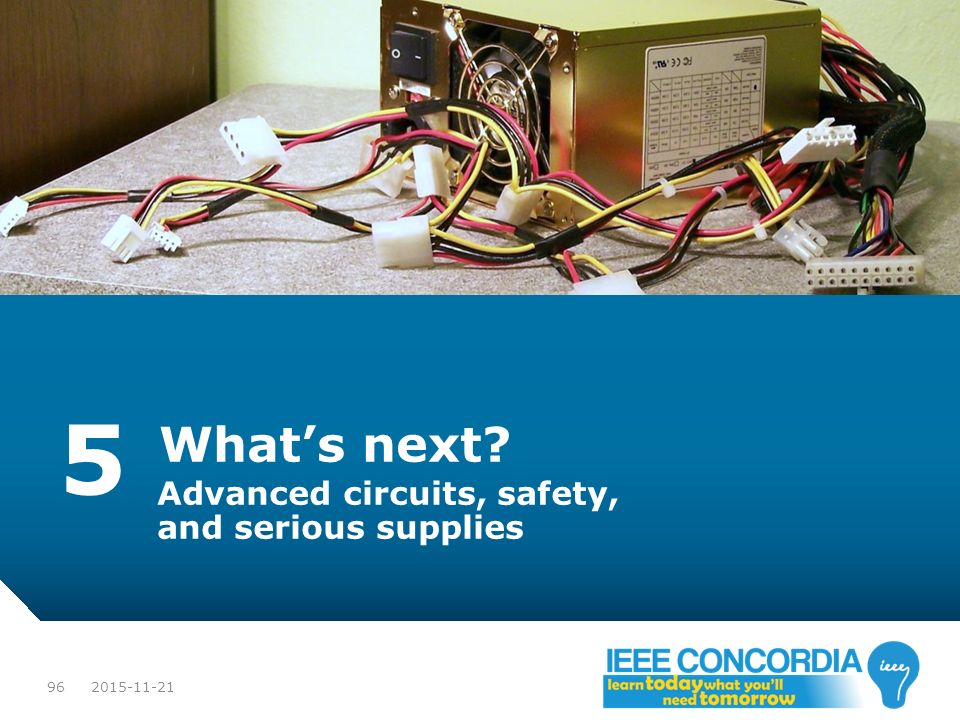
5 What’s next? Advanced circuits, safety, and serious supplies
97
5 More: Performance & safety
Transients: transition when something changes When turning on When output current changes When input voltage changes Transients can go above desired output voltage Depends on quality of controller + your design… May damage circuits! Reason #76 not to buy cheap knockoff phone chargers… Serious projects: analyze these!

98
5 More: Isolation and safety
Various safety devices Usage details outside of scope of workshop Critical to good & safe designs! Fuse: physically open-circuits if current too high Circuit breaker: like fuse but resettable PTC: automatic resetting “fuse” Higher temperature = becomes very high resistance MOV: metal oxide varistor Short-circuits if voltage above a certain value

99
5 More: Isolation and safety
Safety design features: choice of topology Isolated switching power supply Output “floating” relative to input voltage: no common ground Less dangerous to interconnect different devices/equipment Protect circuit from surges/spikes (depends on design) Simplest isolator: a transformer (unless the two sides shorted!) Optocoupling (signal isolation) Prevent surges/spikes/failures damaging controller circuits Maintain isolation for an isolated switching supply’s feedback Current limiting/short-circuit protection
 Simplest isolator: a transformer (unless the two sides shorted!) Optocoupling (signal isolation) Prevent surges/spikes/failures damaging controller circuits. Maintain isolation for an isolated switching supply’s feedback. Current limiting/short-circuit protection")
100
5 More: Switching regulators
Better/safer topologies of switching regulators Isolated switched-mode power supplies Flyback, RCC, Half-Forward, Forward, Resonant Forward, Push- Pull, Half-Bridge, Full-Bridge, Isolated Ćuk Forward converter used in phone chargers Uses transformers (high frequency = small, lightweight, cheap) Also more non-isolated SMPS Split-pi, Ćuk, SEPIC, Zeta Wall-plug power supplies use these better topologies! Buck/boost only used when you already have a good power supply and just need different voltages internally.
 Also more non-isolated SMPS. Split-pi, Ćuk, SEPIC, Zeta. Wall-plug power supplies use these better topologies! Buck/boost only used when you already have a good power supply and just need different voltages internally")
101
5 More: AC-DC Converters
Advanced rectifier Full-wave rectifier using thyristors (SCRs) Controllable diodes (control turn-on) AC-DC with output voltage control Can be used instead of a transformer Needs better filtering, more complicated (control circuit) Animation of changing output voltage with thyristors:
 Controllable diodes (control turn-on) AC-DC with output voltage control. Can be used instead of a transformer. Needs better filtering, more complicated (control circuit) Animation of changing output voltage with thyristors:")
102
5 More: AC-AC Converters
AC-AC regulator using a TRIAC TRIAC: Bi-directional thyristor AC-AC voltage control (not frequency) Can “cut off” part of AC wave (voltage ↓) DC-AC inverter: transistors High-frequency PWM sine wave + filter Control AC voltage and frequency “H-bridge” circuit can be used for this See ELEC433 TRIAC regulator: synchronous or mains motor control; light dimmer Inverter: induction motor control TRIAC symbol. [PD] No author.
 Can cut off part of AC wave (voltage ↓) DC-AC inverter: transistors. High-frequency PWM sine wave + filter. Control AC voltage and frequency. H-bridge circuit can be used for this. See ELEC433. TRIAC regulator: synchronous or mains motor control; light dimmer. Inverter: induction motor control. TRIAC symbol. [PD] No author")
103
5 More: Constant current supplies
We’ve only talked about constant-voltage… Constant-current supplies exist too! e.g. for driving high-power/lighting LEDs Simple up to 1A: LM317-based circuit [CC] SilverSrv. LM317_1A_ConstCurrent.svg

104
6 Real-world PSUs Once you’ve got this advanced stuff down
Image: Computer ATX power supply. Source: [PD] mboverlord.

105
6 Applications to Real-World PSUs
Combine these converters and regulators together Often need several voltages: e.g. 3.3V, 5V, 12V May require low noise output (SMPS too noisy?)
")
106
6 Applications to Real-World PSUs
Switch-mode power supply (no safety/isolation) Rectifier + Filter 12V Buck Regulator 5V Linear Regulator 7V Buck Regulator Inverting –5V Linear Regulator 3.3V Linear Regulator Conceptual block diagram of a switch-mode power supply featuring a high-current 12V rail and ±5V and 3.3V low-current low-noise rails. [PD] Marc-Alexandre Chan. Original.
 Rectifier. + Filter. 12V Buck Regulator. 5V Linear. Regulator. 7V Buck Regulator. Inverting. –5V Linear. Regulator. 3.3V Linear. Regulator. Conceptual block diagram of a switch-mode power supply featuring a high-current 12V rail and ±5V and 3.3V low-current low-noise rails. [PD] Marc-Alexandre Chan. Original")
107
7. Applications to Real-World PSUs
a) ATX power supply. b) Typical block diagram of an ATX power supply. [PD] mboverlord. [O] ON Semiconductor. Educational use.
 ATX power supply. b) Typical block diagram of an ATX power supply. [PD] mboverlord. [O] ON Semiconductor. Educational use")
108
What next? Designing your own power supply
Overvoltage protection, current limiting, short circuit protection, reliability/resistance to failure, isolation, load and line regulation, transient response, cooling, etc. Understanding specifications for choosing a supply Load and line reg., transient response, min/max load, cooling requirements, protection measures etc. Understanding the closed-loop controller Control systems (ELEC372 and related 400-level courses) Electronics (for analog controller: ELEC311, ELEC312) Real-time systems (if digital/software: ELEC483)
 Electronics (for analog controller: ELEC311, ELEC312) Real-time systems (if digital/software: ELEC483)")
109
Thank for you participating in this workshop!
To contact the presenter: Marc-Alexandre Chan Info & downloads: Questions? Project ideas? Want to try something out in the lab? us! Or come visit us!

Similar presentations


>")
>")


