Download presentation
Presentation is loading. Please wait.

1
Teachers Name - Suman Sarker Subject Name Subject Name – Industrial Electronics (6832) Department Department – Computer (3rd) IDEAL INSTITUTE OF SCIENCE & TECHNOLOGY
 Department Department – Computer (3rd) IDEAL INSTITUTE OF SCIENCE & TECHNOLOGY")
2
Lecture no- 08 CH-08 CH-08 THE FEATURES OF OPERATIONAL AMPLIFIER

3
Operational amplifier A μA741 integrated circuit, one of the most successful operational amplifiers.

4
An operational amplifier ("op-amp") is a DC-coupled high-gainelectronic voltage amplifier with a differential input and, usually, a single-ended output. [1] In this configuration, an op-amp produces an output potential (relative to circuit ground) that is typically hundreds of thousands of times larger than the potential difference between its input terminalsDCcoupledgainamplifierdifferential input [1]
 that is typically hundreds of thousands of times larger than the potential difference between its input terminalsDCcoupledgainamplifierdifferential input [1].")
5
Operational amplifiers had their origins in analog computers, where they were used to do mathematical operations in many linear, non- linear and frequency-dependent circuits. The popularity of the op-amp as a building block in analog circuits is due to its versatility. Due to negative feedback, the characteristics of an op-amp circuit, its gain, input and output impedance, bandwidth etc. are determined by external components and have little dependence on temperature coefficients or manufacturing variations in the op-amp itself. analog computers analog circuits negative feedback gain output impedance bandwidth Op-amps are among the most widely used electronic devices today, being used in a vast array of consumer, industrial, and scientific devices. Many standard IC op-amps cost only a few cents in moderate production volume; however some integrated or hybrid operational amplifiers with special performance specifications may cost over $100 US in small quantities. [3] Op-amps may be packaged as components, or used as elements of more complex integrated circuits. [3]

6
An op-amp without negative feedback (a comparator) The amplifier's differential inputs consist of a non-inverting input (+) with voltage V + and an inverting input (–) with voltage V − ; ideally the op-amp amplifies only the difference in voltage between the two, which is called thedifferential input voltage. The output voltage of the op-amp V out is given by the equation:

7
An op-amp with negative feedback (a non-inverting amplifier) If predictable operation is desired, negative feedback is used, by applying a portion of the output voltage to the inverting input. The closed loopfeedback greatly reduces the gain of the circuit. When negative feedback is used, the circuit's overall gain and response becomes determined mostly by the feedback network, rather than by the op-amp characteristics. If the feedback network

8
An equivalent circuit of an operational amplifier that models some resistive non-ideal parameters.

10
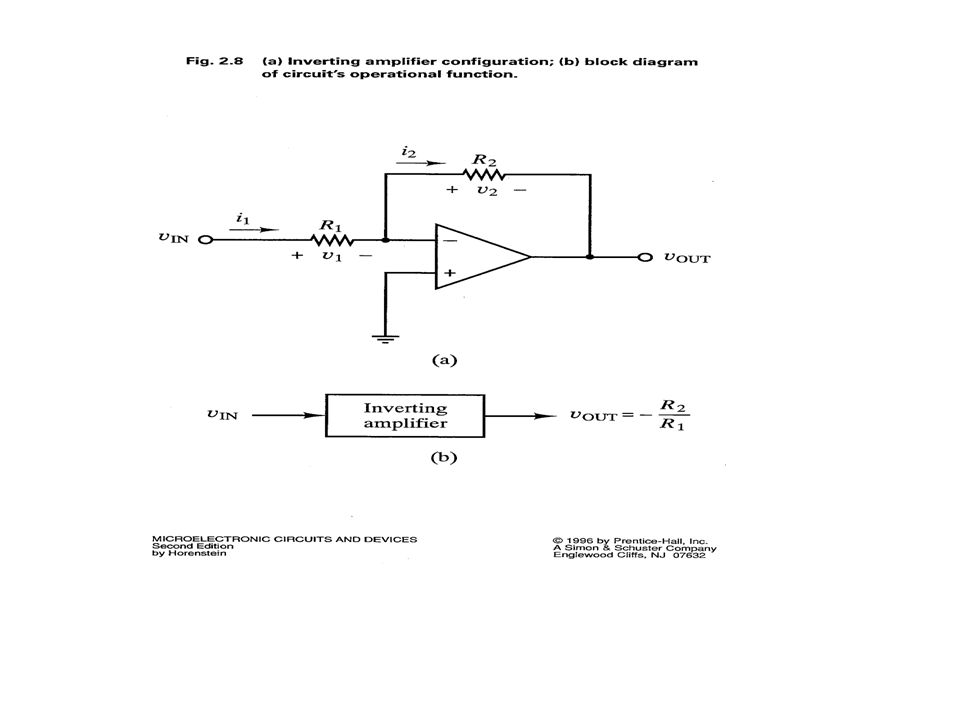
The non-inverting op-amp configuration of slide 2-4 has an apparent input resistance of infinity, since i IN = 0 and R IN = v IN /i IN = v IN /0 = infinity The inverting op-amp configuration, however, has an apparent input resistance of R1 since R IN = v IN /i IN = v IN /[(v IN – 0)/R1] = R1
![The non-inverting op-amp configuration of slide 2-4 has an apparent input resistance of infinity, since i IN = 0 and R IN = v IN /i IN = v IN /0 = infinity The inverting op-amp configuration, however, has an apparent input resistance of R1 since R IN = v IN /i IN = v IN /[(v IN – 0)/R1] = R1](http://images.slideplayer.com/27/9020466/slides/slide_10.jpg "The non-inverting op-amp configuration of slide 2-4 has an apparent input resistance of infinity, since i IN = 0 and R IN = v IN /i IN = v IN /0 = infinity The inverting op-amp configuration, however, has an apparent input resistance of R1 since R IN = v IN /i IN = v IN /[(v IN – 0)/R1] = R1")
11
op-amps into one circuit Using superposition of the results from the two previous cases, we can write v OUT = [(R1 + R2)/R1]v 1 – (R2/R1)v 2 The gain factors for both inputs are different, however We can obtain the same gain factors for both v 1 and v 2 by using the modified circuit below Here the attenuation network at v 1 delivers a reduced input v+ = v 1 (R2/(R1 + R2)) Replacing v 1 in the expression above by the attenuation factor, gives us v OUT = (R2/R1)(v 1 – v 2 ) The difference amplifier will work properly if the attenuation network resistors (call them R3 & R4) are related to the feedback resistors R1 & R2 by the relation R3/R4 = R1/R2 (i.e. same ratio)
![op-amps into one circuit Using superposition of the results from the two previous cases, we can write v OUT = [(R1 + R2)/R1]v 1 – (R2/R1)v 2 The gain factors for both inputs are different, however We can obtain the same gain factors for both v 1 and v 2 by using the modified circuit below Here the attenuation network at v 1 delivers a reduced input v+ = v 1 (R2/(R1 + R2)) Replacing v 1 in the expression above by the attenuation factor, gives us v OUT = (R2/R1)(v 1 – v 2 ) The difference amplifier will work properly if the attenuation network resistors (call them R3 & R4) are related to the feedback resistors R1 & R2 by the relation R3/R4 = R1/R2 (i.e.](http://images.slideplayer.com/27/9020466/slides/slide_11.jpg "same ratio).")
12
The example of Fig’s 2.14 and 2.15 in the text shows a difference amplifier used with a bridge circuit and strain gauge to measure strain.

14
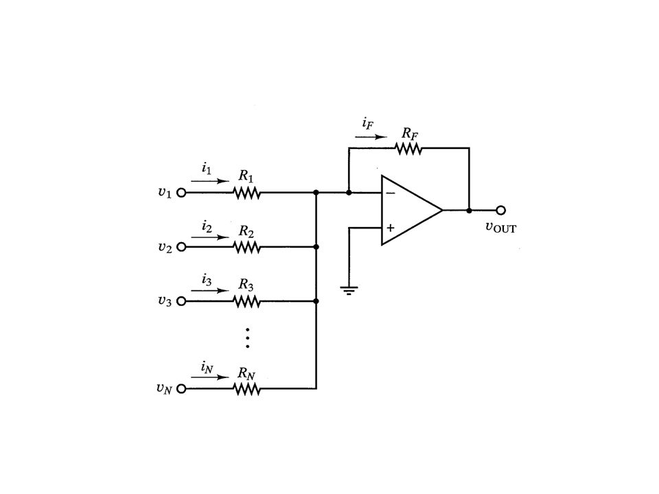
A summation op-amp (shown at left) can be used to obtain a weighted sum of inputs v1…v N The gain for any input k is given by R F /R k If any input goes positive, v OUT goes negative just enough to force the input v- to zero, due to the virtual short nature of the op-amp Combining all inputs, we have v OUT = -R F (v 1 /R 1 + v 2 /R 2 +.. + v N /R N ) The input resistance for any input k is given by R k due to the virtual short between v- and v+ Example 2.5 – use as an audio preamp with individual adjustable gain controls Note effect of microphone’s internal resistance
 The input resistance for any input k is given by R k due to the virtual short between v- and v+ Example 2.5 – use as an audio preamp with individual adjustable gain controls Note effect of microphone’s internal resistance.")
15
Given an input signal of 4V square wave for 10 ms duration, what is the integrator output versus time for the integrator circuit at the left?

16
Using the integral expression from the previous chart, the capacitor voltage will increase linearly in time (1/R 1 C) 4t = 0.8t V/ms during the square wave duration The output will therefore reduce linearly in time by – 0.8t V/ms during the pulse duration, falling from 0 to –8 volts, as shown in the figure at left Since at 10 ms the output will be –8 V > V NEG, the op-amp will not saturate during the 10 ms input pulse
 4t = 0.8t V/ms during the square wave duration The output will therefore reduce linearly in time by – 0.8t V/ms during the pulse duration, falling from 0 to –8 volts, as shown in the figure at left Since at 10 ms the output will be –8 V > V NEG, the op-amp will not saturate during the 10 ms input pulse")
17
Next Lecture POWER SWITCHING DEVICE

Similar presentations


 Circuits with Op-Amps (3.3) Prof. Phillips February 19, 2003.>")


>")


