Download presentation
Presentation is loading. Please wait.

1
Transformer Protection Over-current protection in the form of fuses may be the only protection provided to a small 100 kVA, 11 kV/440 V distribution transformer. A 250 MVA, 15 kV/400 kV generator-transformer in a large thermal power station,on the other hand, may be provided with very elaborate protection. This may consist of percentage differential protection (with harmonic restraint), a protection against incipient faults and a protection against over-fluxing as primary protection. These will be backed up by the over- current protection.
, a protection against incipient faults and a protection against over-fluxing as primary protection. These will be backed up by the over- current protection..")
2
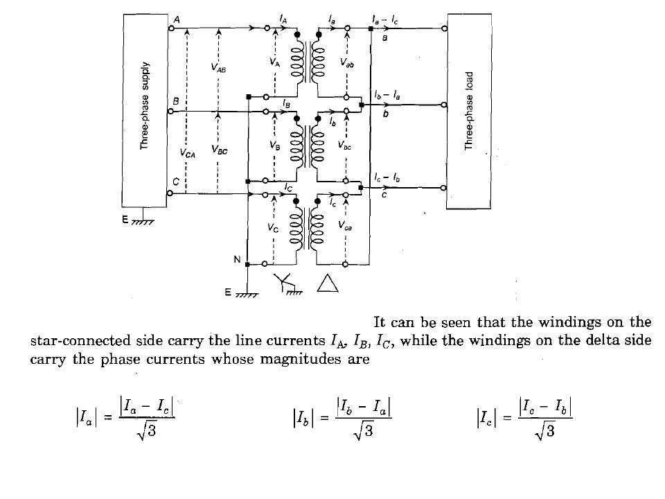
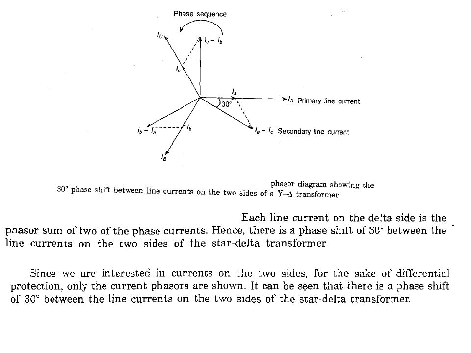
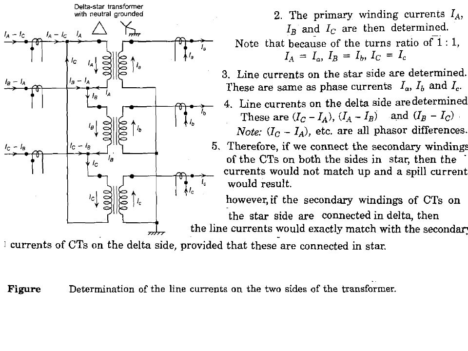
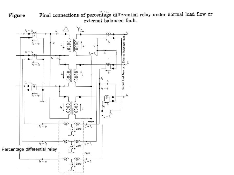
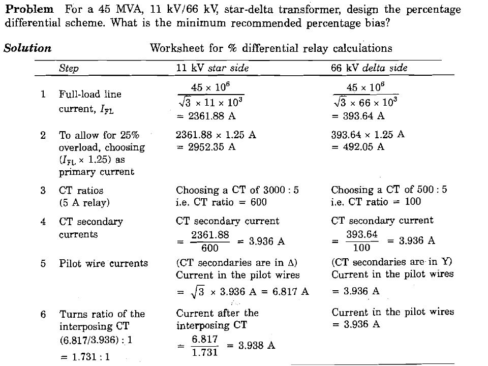
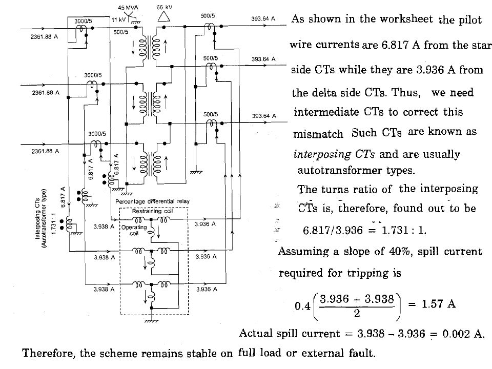
Transformer connection There are four basic types of connections of a three-phase transformer, namely Y-Y,Y-Δ, Δ -Y and Δ- Δ. The Y- Δ and the Δ -Y transformers introduce certain phase shifts between the voltages and currents on the primary and the secondary side. These phase shifts have to be carefully considered while applying differential protection. While connecting the CT secondary windings, we can choose such connections that nullify the phase shift. Further, because of transformation ratio between the primary and the secondary sides of the power transformer, the primary currents for the CTs on the two sides will be different. The CTs must, therefore, have such ratio of transformation that currents in the relay pilot wires, coming from the CTs on the two sides are equal. Thus, ratios of transformation of the CTs on the primary and secondary side of the transformer, will in general, be different. This will ensure that during normal load flow as well as during external fault conditions, the differential scheme remains stable.

5
Types of Faults in Transformers The following is a brief summary of the types of faults that can occur in a power transformer: HV and LV bushing flashovers (external to the tank) HV winding earth fault LV winding earth fault Inter-turn fault Core fault Tank fault. Phase-to-phase faults within the tank of a transformer are relatively rare by virtue of its construction. They are more likely to occur external to the tank on the HV and LV bushings. If a transformer develops a winding fault, the level of fault current will be dictated by: Source impedance Method of neutral earthing Leakage reactance Position of fault in winding (i.e. fault voltag e).
..")
6
Percentage Differential Protection of Transformers Factors Affecting Differential Protection In applying differential protection, several factors must be considered: 1. Magnetizing inrush current, overexcitation, and CT saturation. These conditions can result in an unbalance to the currents applied to thevrelay, compared with the expected currents when power flow into the transformer is equal to the power flow out of the transformer. 2. Different voltage levels; hence, the current transform ers are of different types, ratios, and performance char acteristics. 3. Phase shifts in wye–delta -connected banks. 4. Transformer taps for voltage cont ol. 5. Phase shift or voltage taps in regulating transformers.

7
Development of Connections

11
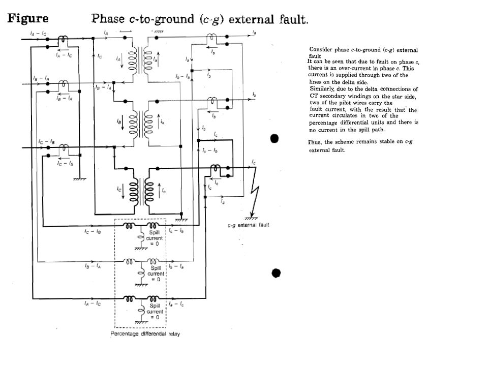
Phase c-to-Ground (c-g) Internal Fault
 Internal Fault")
14
Over-current Protection Such a scheme may serve the purpose of providing either the primary protection for smaller transformers or the back-up protection for bigger transformers. The pick-up value of the phase-fault over-current units is set such that they do not pick up on maxir.um permissible overload, but are sensitive enough to pick up on the smallest phase fault. The pick-up of the earth fault relay, on the other hand, is independent of the loading of the transformer.

15
The neutral current under load conditions is quite small. The neutral current is essentially because of load unbalance. It is interesting to note that the third harmonic currents, in particular and triple-n harmonics (harmonics of order 3, 6, 9,...) in general, which arise due to distortions introduced by electronic loads, also end up as zero sequence currents and flow through the neutral.
 in general, which arise due to distortions introduced by electronic loads, also end up as zero sequence currents and flow through the neutral..")
16
Restricted Earth Fault Protection(High Resistance Ground Fault) A percentage differential relay has a certain minimum value of pick-up for internal faults. Faults with fault current below this value are not detected by the percentage differential relay. Winding-to-core faults, which are of the single phase-to-ground type, involving high resistance, fall in this category. Therefore, we must have a more sensitive relaying scheme to cater for high resistance ground faults. The reach of such a protection must be restricted to the winding of the transformer,otherwise it may operate for any ground fault, anywhere in the system, beyond the transformer. Hence, such protection is known as restricted earth fault protection.

17
High Resistance Ground Faults on the Delta Side If there is a fault on the star side then the currents flow in the lines connected to the delta side in such a way that there is no spill current through the relay on the CT secondary side, thus the reach is automatically restricted to the delta side. Since this is a current balance scheme, it is independent of the load current and hence can be made as sensitive as desired.

18
High Resistance Ground Faults on the Star Side Ground faults beyond the star side CTs, anywhere in the system,do cause current to flow on the secondary of the CTs. However, the currents circulate through the CT in the neutral path and the CT in faulted phase. Thus, no spill current flows and the scheme remains stable on external faults.

19
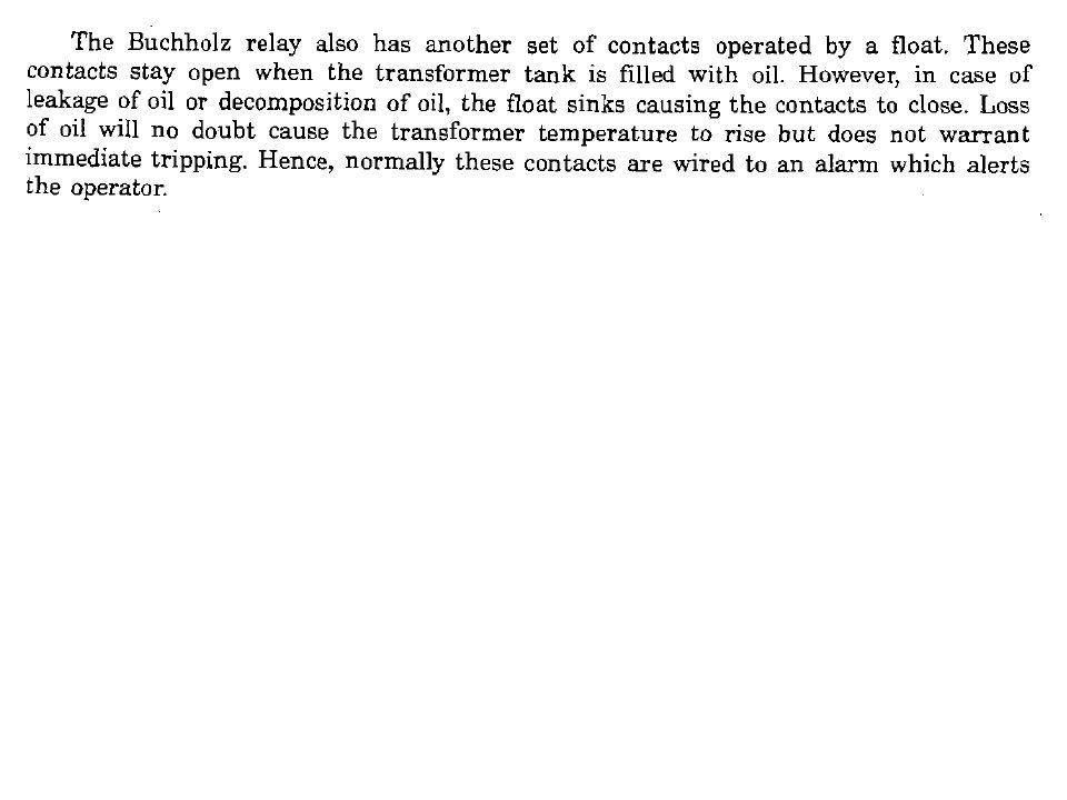
Incipient Faults in Transformers Faults which are not significant in the beginning but which slowly develop into serious faults are known as incipient faults. Buchholz relay provides protection against such incipient faults. Buchholz Relay

21
Transformer Protection Application Chart

Similar presentations


>")

 which link the same, low reluctance, magnetic path. One terminal.>")


>")
