Download presentation
Presentation is loading. Please wait.

3
THE ANALYSIS WORKFLOW

4
The specification document Informal specifications The analysis workflow Extracting the entity classes Functional modeling: The elevator problem case study Entity class modeling: The elevator problem case study

5
5

6
OOA is a semiformal analysis technique for the object-oriented paradigm ◦ There are over 60 equivalent techniques ◦ Today, the Unified Process is the only viable alternative During this workflow ◦ The classes are extracted Remark ◦ The Unified Process assumes knowledge of class extraction

7
The analysis workflow has two aims ◦ Obtain a deeper understanding of the requirements ◦ Describe them in a way that will result in a maintainable design and implementation

8
1. Entity classes ◦ Models long-lived information ◦ Examples: Account Class, Investment Class 2. Boundary classes ◦ Models the interaction between the product and the environment ◦ A boundary class is generally associated with input or output ◦ Examples: Investments Report Class, Mortgages Report Class 3. Control classes ◦ Models complex computations and algorithms ◦ Example: Estimate Funds for Week Class

9
Stereotypes (extensions of UML) Figure 11.1
 Figure 11.1")
10
Perform the following three steps incrementally and iteratively ◦ Functional modeling Present scenarios of all the use cases (a scenario is an instance of a use case) ◦ Class modeling Determine the entity classes and their attributes Determine the interrelationships and interactions between the entity classes Present this information in the form of a class diagram ◦ Dynamic modeling Determine the operations performed by or to each entity class Present this information in the form of a statechart
 ◦ Class modeling Determine the entity classes and their attributes Determine the interrelationships and interactions between the entity classes Present this information in the form of a class diagram ◦ Dynamic modeling Determine the operations performed by or to each entity class Present this information in the form of a statechart")
11
A product is to be installed to control n elevators in a building with m floors. The problem concerns the logic required to move elevators between floors according to the following constraints: 1.Each elevator has a set of m buttons, one for each floor. These illuminate when pressed and cause the elevator to visit the corresponding floor. The illumination is canceled when the corresponding floor is visited by the elevator 2.Each floor, except the first and the top floor, has two buttons, one to request an up-elevator, one to request a down-elevator. These buttons illuminate when pressed. The illumination is canceled when an elevator visits the floor, then moves in the desired direction 3.If an elevator has no requests, it remains at its current floor with its doors closed

12
For the elevator problem, there are only two possible use cases ◦ Press an Elevator Button, and ◦ Press a Floor Button Figure 11.2

13
Extract classes and their attributes ◦ Represent them using a UML diagram One alternative: Deduce the classes from use cases and their scenarios ◦ Possible danger: Often there are many scenarios, and hence ◦ Too many candidate classes Other alternatives: ◦ CRC cards (if you have domain knowledge) ◦ Noun extraction
 ◦ Noun extraction")
14
A two-stage process Stage 1. Concise problem definition ◦ Describe the software product in single paragraph

15
Stage 2. Identify the nouns ◦ Identify the nouns in the informal strategy ◦ Buttons in elevators and on the floors control the movement of n elevators in a building with m floors. Buttons illuminate when pressed to request the elevator to stop at a specific floor; the illumination is canceled when the request has been satisfied. When an elevator has no requests, it remains at its current floor with its doors closed Use the nouns as candidate classes

16
Nouns ◦ button, elevator, floor, movement, building, illumination, request, door ◦ floor, building, door are outside the problem boundary — exclude ◦ movement, illumination, request are abstract nouns — exclude (they may become attributes) Candidate classes: ◦ Elevator Class and Button Class Subclasses: ◦ Elevator Button Class and Floor Button Class
 Candidate classes: ◦ Elevator Class and Button Class Subclasses: ◦ Elevator Button Class and Floor Button Class")
17
Problem ◦ Buttons do not communicate directly with elevators ◦ We need an additional class: Elevator Controller Class Figure 11.5

18
All relationships are now 1-to-n ◦ This makes design and implementation easier Figure 11.6

19
Used since 1989 for OOA For each class, fill in a card showing ◦ Name of Class ◦ Functionality (Responsibility) ◦ List of classes it invokes (Communication) Now CRC cards are automated (CASE tool component)
 ◦ List of classes it invokes (Communication) Now CRC cards are automated (CASE tool component)")
20
A statechart is constructed by modeling the events of the scenarios Produce a UML statechart State, event, and predicate are distributed over the statechart Figure 11.7

21
Consider responsibility ◦ 1.Turn on elevator button This is totally inappropriate for the object- oriented paradigm ◦ Responsibility-driven design has been ignored ◦ Information hiding has been ignored Responsibility 1.Turn on elevator button should be 1.Send message to Elevator Button Class to turn itself on

22
Also, a class has been overlooked The elevator doors have a state that changes during execution (class characteristic) ◦ Add class Elevator Doors Class ◦ Safety considerations Modify the CRC card
 ◦ Add class Elevator Doors Class ◦ Safety considerations Modify the CRC card")
23
Figure 11.9

24
Having modified the class diagram, reconsider the ◦ Use-case diagram (no change) ◦ Class diagram (see the next slide) ◦ Statecharts ◦ Scenarios (see the slide after the next slide)
 ◦ Class diagram (see the next slide) ◦ Statecharts ◦ Scenarios (see the slide after the next slide)")
25
Figure 11.10

26
Each ◦ Input screen, ◦ Output screen, and ◦ Report is modeled by its own boundary class Each nontrivial computation is modeled by a control class

27
Figure 11.18

28
Operations performed on the two entity classes are likely to be very similar ◦ Insertions, deletions, and modifications ◦ All members of both entity classes have to be printed on demand Mortgage Class and Investment Class should be subclasses of a superclass called Asset Class

29
Figure 11.19

30
Figure 11.21

31
Dynamic modeling is the third step in extracting the entity classes A statechart is constructed that reflects all the operations performed by or to the software product The operations are determined from the scenarios

32
Figure 11.22

33
The statechart reflects the operations of the complete MSG Foundation information system ◦ The solid circle on the top left represents the initial state, the starting point of the statechart ◦ The white circle containing the small black circle on the top right represents the final state ◦ States other than the initial and final states are represented by rectangles with rounded corners ◦ The arrows represent possible transitions from state to state

34
An MSG staff member selects an option by clicking on the menu This graphical user interface (GUI) requires special software Figure 11.23
 requires special software Figure 11.23")
35
The only way a value can be stored on a long-term basis is as an attribute of an instance of that class or its subclasses Another entity class is needed for storing the estimated annual operating expenses ◦ MSG Application Class

36
MSG Application Class has other attributes as well ◦ Attributes that do not appertain to the assets Figure 11.25

37
The class diagram redrawn to show the prototypes Figure 11.26

38
It is usually easy to extract boundary classes ◦ Each input screen, output screen, and printed report is generally modeled by a boundary class One screen should be adequate for all four MSG Foundation use cases Estimate Funds Available for Week Manage an Asset Update Estimated Annual Operating Expenses Produce a Report Accordingly there is one initial boundary class ◦ User Interface Class

39
Three reports have to be printed ◦ The estimated funds for the week report ◦ The listing of all mortgages ◦ The listing of all investments Each of these has to be modeled by a separate boundary class ◦ Estimated Funds Report Class ◦ Mortgages Report Class ◦ Investments Report Class

40
Here are the four initial boundary classes Figure 11.27

41
There are three reports: ◦ The purchases report ◦ The sales report ◦ The future trends report The content of each report is different ◦ Each report therefore has to be modeled by a separate boundary class

42
l Each computation is usually modeled by a control class l The MSG Foundation case study has just one – Estimate the funds available for the week l There is one initial control class Figure 11.28

43
Sequence diagram equivalent to the communication diagram (of the realization of the scenario of the use case) Figure 11.35
 Figure 11.35")
44
The strength of a sequence diagram is that it shows the flow of messages and their order unambiguously ◦ When transfer of information is the focus of attention, a sequence diagram is superior to a communication diagram A communication diagram is similar to a class diagram ◦ When the developers are concentrating on the classes, a communication diagram is more useful than the equivalent sequence diagram

45
Sequence diagram equivalent to the communication diagram (of the realization of the scenario of the use case) Figure 11.44
 Figure 11.44")
46
Boundary class User Interface Class appears in all the realizations ◦ The same screen will be used for all commands of the information system Revised menu Figure 11.45

47
Figure 11.60

48
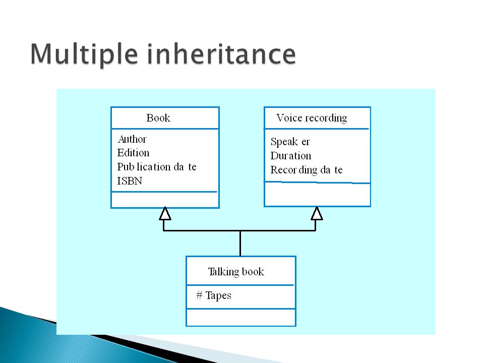
Rather than inheriting the attributes and services from a single parent class, a system which supports multiple inheritance allows object classes to inherit from several super-classes. This can lead to semantic conflicts where attributes/services with the same name in different super-classes have different semantics. Multiple inheritance makes class hierarchy reorganisation more complex.

50
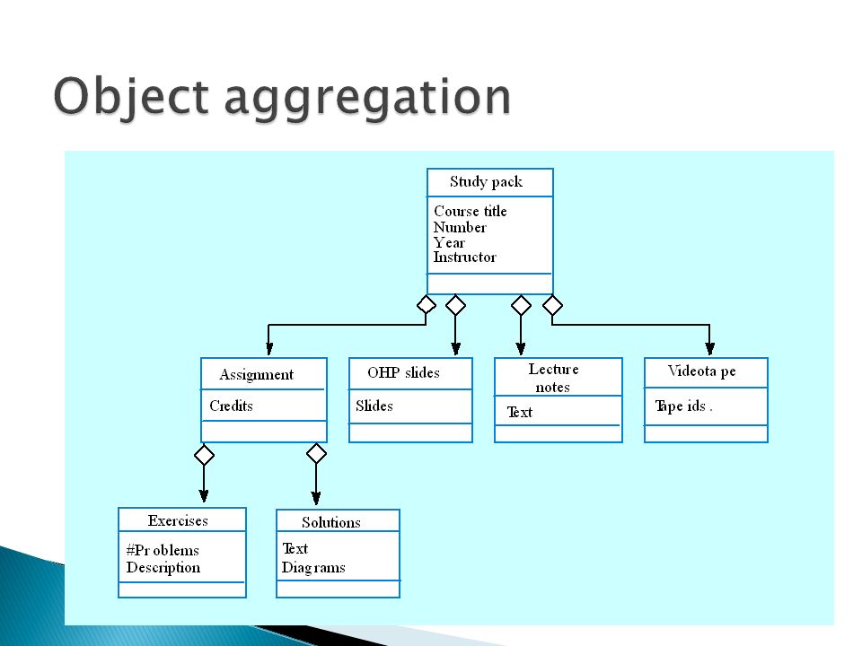
An aggregation model shows how classes that are collections are composed of other classes. Aggregation models are similar to the part-of relationship in semantic data models.

52
The Unified Process is use-case driven ◦ The use cases and the artifacts derived from them replace the traditional textual specification document The client must be shown each use case and associated artifacts, both diagrammatic and textual ◦ These UML diagrams convey to the client more information more accurately than the traditional specification document ◦ The set of UML diagrams can also play the same contractual role as the traditional specification document

53
A scenario is a specific execution sequence The client can therefore appreciate how the product works equally well from ◦ A use case together with its scenarios, or ◦ A rapid prototype The difference is ◦ The use cases are successively refined, with more information added each time, whereas ◦ The rapid prototype is discarded

54
However, a rapid prototype of the user interface is required ◦ Specimen screens and reports are needed (not a complete rapid prototype)
")
55
Diagrams play a major role in the analysis workflow Diagrams often change ◦ We need a diagramming tool ◦ Many tools go further All modern tools support UML ◦ Commercial examples IBM Rational Rose Together ◦ Open-source example ArgoUML

56
Do not cross the boundary into the design workflow Do not allocate methods to classes yet ◦ Reallocating methods to classes during stepwise refinement is wasted effort

Similar presentations