Download presentation
Presentation is loading. Please wait.

1
Unit 1 Minimization Techniques and Logic Gates

2
Introduction to Digital Systems Analog devices and systems process time-varying signals that can take on any value across a continuous range. Digital systems use digital circuits that process digital signals which can take on one of two values, we call: 0 and 1 (digits of the binary number system) or LOW and HIGH or FALSE and TRUE Digital computers represent the most common digital systems. Once-analog Systems that use digital systems today: –Audio recording (CDs, DAT, mp3) – Phone system switching –Automobile engine control –Movie effects –Still and video cameras…. High Low Digital circuit inputsoutputs :: Analog Signal Digital Signal
 or LOW and HIGH or FALSE and TRUE Digital computers represent the most common digital systems. Once-analog Systems that use digital systems today: –Audio recording (CDs, DAT, mp3) – Phone system switching –Automobile engine control –Movie effects –Still and video cameras…. High Low Digital circuit inputsoutputs :: Analog Signal Digital Signal.")
3
3 Advantages of Digital Systems Over Analog Systems 1.Reproducibility of the results 2.Accuracy of results 3.More reliable than analog systems due to better immunity to noise. 4.Ease of design: No special math skills needed to visualize the behavior of small digital (logic) circuits. 5.Flexibility and functionality. 6.Programmability. 7.Speed: A digital logic element can produce an output in less than 10 nanoseconds (10 -8 seconds). 8.Economy: Due to the integration of millions of digital logic elements on a single miniature chip forming low cost integrated circuit (ICs).
 circuits. 5.Flexibility and functionality. 6.Programmability. 7.Speed: A digital logic element can produce an output in less than 10 nanoseconds (10 -8 seconds). 8.Economy: Due to the integration of millions of digital logic elements on a single miniature chip forming low cost integrated circuit (ICs)..")
4
4 Boolean Algebra Boolean Algebra named after George Boole who used it to study human logical reasoning – calculus of proposition. Elements : true or false ( 0, 1) Operations: a OR b; a AND b, NOT a e.g. 0 OR 1 = 1 0 OR 0 = 0 1 AND 1 = 1 1 AND 0 = 0 NOT 0 = 1 NOT 1 = 0 What is an Algebra? (e.g. algebra of integers) set of elements (e.g. 0,1,2,..) set of operations (e.g. +, -, *,..) postulates/axioms (e.g. 0+x=x,..)
 Operations: a OR b; a AND b, NOT a e.g. 0 OR 1 = 1 0 OR 0 = 0 1 AND 1 = 1 1 AND 0 = 0 NOT 0 = 1 NOT 1 = 0 What is an Algebra. (e.g. algebra of integers) set of elements (e.g. 0,1,2,..) set of operations (e.g. +, -, *,..) postulates/axioms (e.g. 0+x=x,..).")
5
Boolean function Boolean function: Mapping from Boolean variables to a Boolean value. Boolean algebra: Deals with binary variables and logic operations operating on those variables.

6
BASIC IDENTITIES OF BOOLEAN ALGEBRA Postulate 1 (Definition): A Boolean algebra is a closed algebraic system containing a set K of two or more elements and the two operators · and + which refer to logical AND and logical OR
: A Boolean algebra is a closed algebraic system containing a set K of two or more elements and the two operators · and + which refer to logical AND and logical OR")
7
Basic Identities of Boolean Algebra (Existence of 1 and 0 element) (1)x + 0 = x (2)x · 0 = 0 (3)x + 1 = 1 (4)x · 1 = 1
 (1)x + 0 = x (2)x · 0 = 0 (3)x + 1 = 1 (4)x · 1 = 1")
8
Basic Identities of Boolean Algebra (Existence of complement) (5) x + x = x (6) x · x = x (7) x + x’ = x (8) x · x’ = 0
 (5) x + x = x (6) x · x = x (7) x + x’ = x (8) x · x’ = 0")
9
Basic Identities of Boolean Algebra (Commutativity): (9) x + y = y + x (10) xy = yx
: (9) x + y = y + x (10) xy = yx")
10
Basic Identities of Boolean Algebra (Associativity): (11) x + ( y + z ) = ( x + y ) + z (12) x (yz) = (xy) z
: (11) x + ( y + z ) = ( x + y ) + z (12) x (yz) = (xy) z")
11
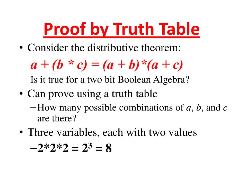
Basic Identities of Boolean Algebra (Distributivity): (13) x ( y + z ) = xy + xz (14) x + yz = ( x + y )( x + z)
: (13) x ( y + z ) = xy + xz (14) x + yz = ( x + y )( x + z)")
12
Basic Identities of Boolean Algebra (DeMorgan’s Theorem) (15) ( x + y )’ = x’ y’ (16) ( xy )’ = x’ + y’
 (15) ( x + y )’ = x’ y’ (16) ( xy )’ = x’ + y’")
13
Basic Identities of Boolean Algebra (Involution) (17) (x’)’ = x
 (17) (x’)’ = x")
21
Function Minimization using Boolean Algebra Examples: (a) a + ab = a(1+b)=a (b) a(a + b) = a.a +ab=a+ab=a(1+b)=a. (c) a + a'b = (a + a')(a + b)=1(a + b) =a+b (d) a(a' + b) = a. a' +ab=0+ab=ab
 a + a b = (a + a )(a + b)=1(a + b) =a+b (d) a(a + b) = a. a +ab=0+ab=ab.")
22
Try F = abc + abc’ + a’c

23
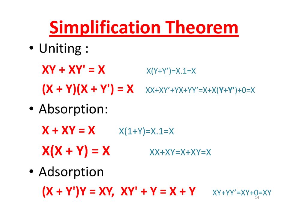
The other type of question Show that; 1- ab + ab' = a 2- (a + b)(a + b') = a 1- ab + ab' = a(b+b') = a.1=a 2- (a + b)(a + b') = a.a +a.b' +a.b+b.b' = a + a.b' +a.b + 0 = a + a.(b' +b) + 0 = a + a.1 + 0 = a + a = a
(a + b ) = a 1- ab + ab = a(b+b ) = a.1=a 2- (a + b)(a + b ) = a.a +a.b +a.b+b.b = a + a.b +a.b + 0 = a + a.(b +b) + 0 = a + a = a + a = a")
24
More Examples Show that; (a) ab + ab'c = ab + ac (b) (a + b)(a + b' + c) = a + bc (a) ab + ab'c = a(b + b'c) = a((b+b').(b+c))=a(b+c)=ab+ac (b) (a + b)(a + b' + c) = (a.a + a.b' + a.c + ab +b.b' +bc) = …
 ab + ab c = ab + ac (b) (a + b)(a + b + c) = a + bc (a) ab + ab c = a(b + b c) = a((b+b ).(b+c))=a(b+c)=ab+ac (b) (a + b)(a + b + c) = (a.a + a.b + a.c + ab +b.b +bc) = …")
25
DeMorgan's Theorem (a) (a + b)' = a'b' (b) (ab)' = a' + b' Generalized DeMorgan's Theorem (a) (a + b + … z)' = a'b' … z' (b) (a.b … z)' = a' + b' + … z‘
 (a + b) = a b (b) (ab) = a + b Generalized DeMorgan s Theorem (a) (a + b + … z) = a b … z (b) (a.b … z) = a + b + … z‘")
26
DeMorgan's Theorem F = ab + c’d’ F’ = ?? F = ab + c’d’ + b’d F’ = ??

27
DeMorgan's Theorem Show that: (a + b.c)' = a'.b' + a'.c'
 = a .b + a .c")
28
More DeMorgan's example Show that: (a(b + z(x + a')))' =a' + b' (z' + x') (a(b + z(x + a')))' = a' + (b + z(x + a'))' = a' + b' (z(x + a'))' = a' + b' (z' + (x + a')') = a' + b' (z' + x'(a')') = a' + b' (z' + x'a) =a‘+b' z' + b'x'a =(a‘+ b'x'a) + b' z' =(a‘+ b'x‘)(a +a‘) + b' z' = a‘+ b'x‘+ b' z‘ = a' + b' (z' + x')
)) =a + b (z + x ) (a(b + z(x + a ))) = a + (b + z(x + a )) = a + b (z(x + a )) = a + b (z + (x + a ) ) = a + b (z + x (a ) ) = a + b (z + x a) =a‘+b z + b x a =(a‘+ b x a) + b z =(a‘+ b x‘)(a +a‘) + b z = a‘+ b x‘+ b z‘ = a + b (z + x )")
29
More Examples (a(b + c) + a'b)'=b'(a' + c') ab + a'c + bc = ab + a'c (a + b)(a' + c)(b + c) = (a + b)(a' + c)
 + a b) =b (a + c ) ab + a c + bc = ab + a c (a + b)(a + c)(b + c) = (a + b)(a + c)")
30
Simplification of Switching Functions

31
Karnaugh Maps (K-Map) A K-Map is a graphical representation of a logic function’s truth table
 A K-Map is a graphical representation of a logic function’s truth table")
32
Two-Variable K-Map

33
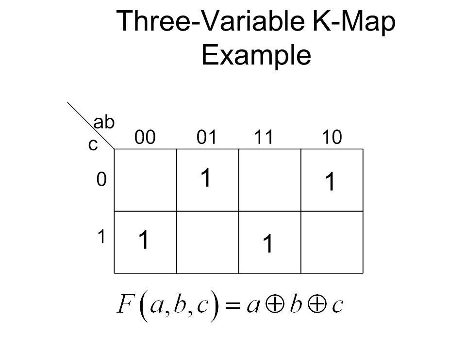
Three-Variable K-Map

35
Edges are adjacent

36
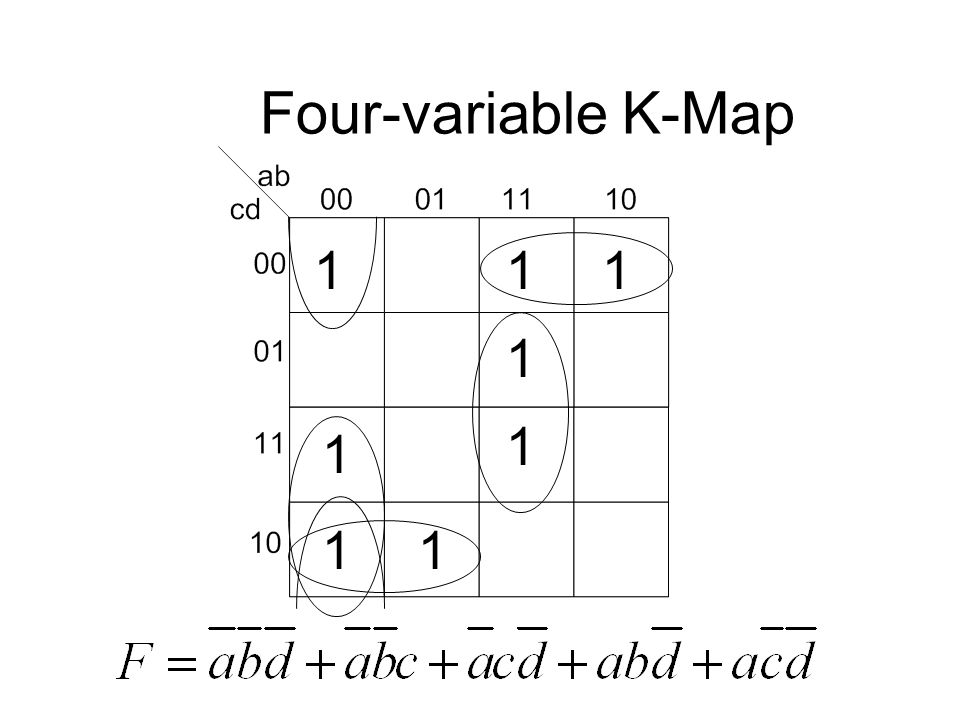
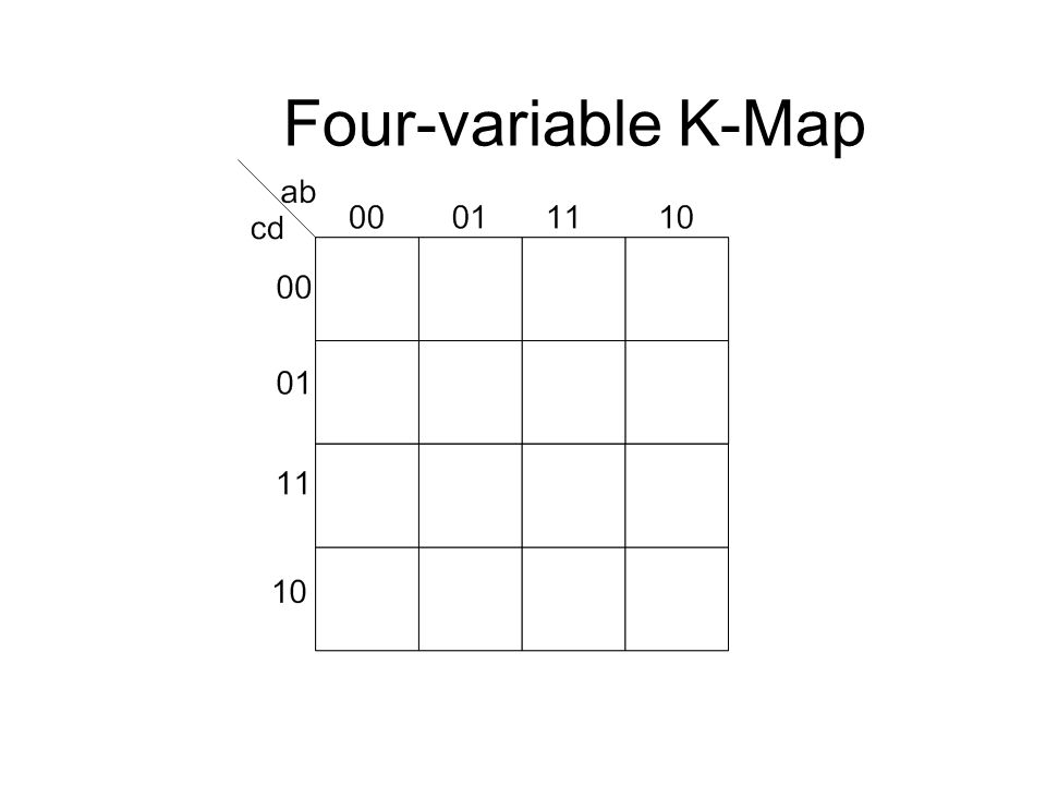
Four-variable K-Map

38
Edges are adjacent

39
Plotting Functions on the K-map SOP Form

40
Canonical SOP Form Three Variable Example using shorthand notation

41
Three-Variable K-Map Example Plot 1’s (minterms) of switching function 11 1 1
 of switching function")
42
Three-Variable K-Map Example Plot 1’s (minterms) of switching function 11 1 1
 of switching function")
43
Four-variable K-Map Example 1 1 1 1 1

44
Karnaugh Maps (K-Map) Simplification of Switching Functions using K-MAPS
 Simplification of Switching Functions using K-MAPS")
45
Terminology/Definition Literal –A variable or its complement Logically adjacent terms –Two minterms are logically adjacent if they differ in only one variable position –Ex: and m6 and m2 are logically adjacent Note: Or, logically adjacent terms can be combined

46
Terminology/Definition Implicant –Product term that could be used to cover minterms of a function Prime Implicant –An implicant that is not part of another implicant Essential Prime Implicant –An implicant that covers at least one minterm that is not contained in another prime implicant Cover –A minterm that has been used in at least one group

47
Guidelines for Simplifying Functions Each square on a K-map of n variables has n logically adjacent squares. (i.e. differing in exactly one variable) When combing squares, always group in powers of 2 m, where m=0,1,2,…. In general, grouping 2 m variables eliminates m variables.
 When combing squares, always group in powers of 2 m, where m=0,1,2,…. In general, grouping 2 m variables eliminates m variables..")
48
Guidelines for Simplifying Functions Group as many squares as possible. This eliminates the most variables. Make as few groups as possible. Each group represents a separate product term. You must cover each minterm at least once. However, it may be covered more than once.

49
K-map Simplification Procedure Plot the K-map Circle all prime implicants on the K- map Identify and select all essential prime implicants for the cover. Select a minimum subset of the remaining prime implicants to complete the cover. Read the K-map

50
Example Use a K-Map to simplify the following Boolean expression

51
Three-Variable K-Map Example Step 1: Plot the K-map 1 1 1 11

52
Three-Variable K-Map Example Step 2: Circle ALL Prime Implicants 1 1 1 11

53
Three-Variable K-Map Example Step 3: Identify Essential Prime Implicants 1 1 1 11 EPI PI

54
Three-Variable K-Map Example Step 4: Select minimum subset of remaining Prime Implicants to complete the cover. 1 1 1 11 EPI PI EPI

55
Three-Variable K-Map Example Step 5: Read the map. 1 1 1 11

56
Solution

57
Example Use a K-Map to simplify the following Boolean expression

58
Three-Variable K-Map Example Step 1: Plot the K-map 11 11

59
Three-Variable K-Map Example Step 2: Circle Prime Implicants 1 1 11 Wrong!! We really should draw A circle around all four 1’s

60
Three-Variable K-Map Example Step 3: Identify Essential Prime Implicants EPI 1 1 11 Wrong!! We really should draw A circle around all four 1’s

61
Three-Variable K-Map Example Step 4: Select Remaining Prime Implicants to complete the cover. EPI 1 1 11

62
Three-Variable K-Map Example Step 5: Read the map. 1 1 11

63
Solution Since we can still simplify the function this means we did not use the largest possible groupings.

64
Three-Variable K-Map Example Step 2: Circle Prime Implicants 1 1 11 Right!

65
Three-Variable K-Map Example Step 3: Identify Essential Prime Implicants EPI 1 1 11

66
Three-Variable K-Map Example Step 5: Read the map. 1 1 11

67
Solution

68
Special Cases

69
Three-Variable K-Map Example 1 1 1 111 1 1

71
1 1 1 1
72
Four Variable Examples

73
Example Use a K-Map to simplify the following Boolean expression

74
Four-variable K-Map 1 1 1 1 11 1 1

75
1 1 1 1 11 1 1

76
1 1 1 1 11 1 1
77
Example Use a K-Map to simplify the following Boolean expression D=Don’t care (i.e. either 1 or 0)
")
78
Four-variable K-Map 1 1 d 1 11 1 1 d d

79
1 1 d 1 11 1 1 d d

80
Five Variable K-Maps

81
Five variable K-map A=1 A=0 Use two four variable K-maps

82
Use Two Four-variable K- Maps A=0 mapA=1 map

83
Five variable example

84
Use Two Four-variable K- Maps A=0 mapA=1 map 1 1 1 1 1 1 1 1

85
Use Two Four-variable K- Maps A=0 mapA=1 map 1 1 1 1 1 1 1 1

86
Five variable example

87
Plotting POS Functions

88
K-map Simplification Procedure Plot the K-map for the function F Circle all prime implicants on the K-map Identify and select all essential prime implicants for the cover. Select a minimum subset of the remaining prime implicants to complete the cover. Read the K-map Use DeMorgan’s theorem to convert F to F in POS form

89
Example Use a K-Map to simplify the following Boolean expression

90
Three-Variable K-Map Example Step 1: Plot the K-map of F 1 1 1 11

91
Three-Variable K-Map Example Step 2: Circle ALL Prime Implicants 1 1 1 11

92
Three-Variable K-Map Example Step 3: Identify Essential Prime Implicants 1 1 1 11 EPI PI

93
Three-Variable K-Map Example Step 4: Select minimum subset of remaining Prime Implicants to complete the cover. 1 1 1 11 EPI PI EPI

94
Three-Variable K-Map Example Step 5: Read the map. 1 1 1 11

95
Solution

116
SOP and POS Forms

117
SOP Given a Table of Combinations –What is the SOP form for the following 3 input / 1 output digital device? SABf 0000 0010 0101 0111 1000 1011 1100 1111

118
Computing the SOP (2) –This SOP has 4 minterms: f = S'AB' + S'AB + SA'B + SAB SABfminterm name 0101m2m2 0111m3m3 1011m5m5 1111m7m7
 –This SOP has 4 minterms: f = S AB + S AB + SA B + SAB SABfminterm name 0101m2m2 0111m3m3 1011m5m5 1111m7m7")
119
Canonical SOP –Boolean functions can use shorthand notation when in SOP form: f = S'AB' + S'AB + SA'B + SAB f(S,A,B) = (m 2,m 3,m 5,m 7 ) or f(S,A,B) = m(2,3,5,7)
 = (m 2,m 3,m 5,m 7 ) or f(S,A,B) = m(2,3,5,7)")
120
Canonical SOP Example –f(x 1,x 2,x 3 ) = m(1,4,5,6) –f = mintermx1x1 x2x2 x3x3 f 00000 10011 20100 30110 41001 51011 61101 71110 x1'x2'x3 + x1x2'x3' + x1x2'x3 + x1x2x3'
 = m(1,4,5,6) –f = mintermx1x1 x2x2 x3x3 f x1 x2 x3 + x1x2 x3 + x1x2 x3 + x1x2x3")
121
Product of Sums Form –An alternate canonical “two-level” format “Product of sums” POS Two levels –OR level followed by AND level –Again, NOT doesn’t count as a level Not a common as SOP, but can be useful in some situations –Which ones?

122
Computing the POS –Identify rows with “0” on output (f = 0) –Represent the input for each 0 row as a maxterm A logical “sum” of the input bits which guarantees that term will be “0” (sum of literals) ABf 000 011 100 110
 –Represent the input for each 0 row as a maxterm A logical sum of the input bits which guarantees that term will be 0 (sum of literals) ABf")
123
Canonical POS Example –f(x 1,x 2,x 3 ) = ( M 0,M 2,M 3,M 7 ) = M(0,2,3,7) –f = maxtermx1x1 x2x2 x3x3 f 00000 10011 20100 30110 41001 51011 61101 71110 (x1+x2+x3)(x1+x2'+x3)(x1+x2'+x3')(x1'+x2'+x3')
 = ( M 0,M 2,M 3,M 7 ) = M(0,2,3,7) –f = maxtermx1x1 x2x2 x3x3 f (x1+x2+x3)(x1+x2 +x3)(x1+x2 +x3 )(x1 +x2 +x3 )")
124
NAND/NOR Circuits

125
Completeness of NAND Any Boolean function can be implemented using just NAND gates. Why? –Need AND, OR, and NOT –NOT: 1-input NAND (or 2-input NAND with inputs tied together) –AND: NAND followed by NOT –OR: NAND preceded by NOTs Likewise for NOR
 –AND: NAND followed by NOT –OR: NAND preceded by NOTs Likewise for NOR.")
126
Using NAND as Universal Logic –NOT –AND –OR

127
SOP Using NORs & POS Using NANDs –NANDs are natural for SOP networks You can extend this idea to multi-level circuits as long as the levels alternate AND/OR/AND/OR ending with OR You can implement an SOP circuit using only NOR gates –All gates become NORs; just add an extra “inverter” following the final NOR –NORs are natural for POS networks You can extend this idea to multi-level circuits as long as the levels alternate OR/AND/OR/AND ending with AND You can implement a POS circuit using only NAND gates –All gates become NANDs; just add an extra inverter following the final NAND

128
SOP Using NAND Networks –SOP can be implemented with just NAND gates “pushing the bubbles” Every gate just becomes a NAND!

129
2x1 MUX Using NANDs –Implement f = S'A + SB with NAND gates only –This one is complicated by the inverter on S!

130
POS Using NOR Networks –POS can be implemented with just NOR gates Every gate just becomes a NOR

131
Schematics of DeMorgan’s Laws (x ∙ y)' = x' + y' (x + y)' = x' ∙ y'
 = x + y (x + y) = x ∙ y")
132
Universal Logic Families –Any logic function can be designed using only: AND, OR, NOT NAND NOR –These are called “universal logic families” –Actual components are often designed using either NAND or NOR gates only NAND and NOR require fewer transistors to build Just having a single gate design is simpler than having 3!

133
AND/OR Networks NAND/NAND –Convert multi-level AND/OR net NAND/NAND

134
And Again … But Be Careful conserve the polarity of the input/output signals

135
Logic Gates

136
AND Function Output Y is TRUE if inputs A AND B are TRUE, else it is FALSE. Logic Symbol Text Description Truth Table Boolean Expression AND A B Y Y = A x B = A B = AB AND Symbol

137
OR Function Output Y is TRUE if input A OR B is TRUE, else it is FALSE. Logic Symbol Text Description Truth Table Boolean Expression Y = A + B OR Symbol A B Y OR

138
NOT Function (inverter) Output Y is TRUE if input A is FALSE, else it is FALSE. Y is the inverse of A. Logic Symbol Text Description Truth Table Boolean Expression AY NOT NOT Bar Y = A Y = A’ Alternative Notation Y = !A

139
NAND Function Output Y is FALSE if inputs A AND B are TRUE, else it is TRUE. Logic Symbol Text Description Truth Table Boolean Expression A B Y NAND A bubble is an inverter This is an AND Gate with an inverted output Y = A x B = AB

140
NOR Function Output Y is FALSE if input A OR B is TRUE, else it is TRUE. Logic Symbol Text Description Truth Table Boolean Expression Y = A + B A B Y NOR A bubble is an inverter. This is an OR Gate with its output inverted.

141
Circuit-to-Truth Table Example OR A Y NOT AND B C 2 # of Inputs = # of Combinations 2 3 = 8 0 0 0 0 0 1 0 1 0 0 1 1 1 0 0 1 0 1 1 1 0 1 1 1 A B C Y

142
Circuit-to-Truth Table Example OR A Y NOT AND B C 0 0 0 0 0 1 0 1 0 0 1 1 1 0 0 1 0 1 1 1 0 1 1 1 A B C Y 0 0 0 0 1 0 0 0

143
Circuit-to-Truth Table Example 0 0 0 0 0 1 0 1 0 0 1 1 1 0 0 1 0 1 1 1 0 1 1 1 A B C Y 0 OR A Y NOT AND B C 0 0 1 0 1 1 1 1

144
Circuit-to-Truth Table Example 0 0 0 0 0 1 0 1 0 0 1 1 1 0 0 1 0 1 1 1 0 1 1 1 A B C Y 0 1 0 OR A Y NOT AND B C 0 1 0 0 1 0 0 0

145
Circuit-to-Truth Table Example 0 0 0 0 0 1 0 1 0 0 1 1 1 0 0 1 0 1 1 1 0 1 1 1 A B C Y 0 1 0 0 OR A Y NOT AND B C 0 1 1 0 1 1 1 1

146
Circuit-to-Truth Table Example 0 0 0 0 0 1 0 1 0 0 1 1 1 0 0 1 0 1 1 1 0 1 1 1 A B C Y 0 1 0 1 0 OR A Y NOT AND B C 1 0 0 0 0 0 0 0

147
Circuit-to-Truth Table Example 0 0 0 0 0 1 0 1 0 0 1 1 1 0 0 1 0 1 1 1 0 1 1 1 A B C Y 0 1 0 1 0 0 OR A Y NOT AND B C 1 0 1 0 0 0 0 0

148
Circuit-to-Truth Table Example 0 0 0 0 0 1 0 1 0 0 1 1 1 0 0 1 0 1 1 1 0 1 1 1 A B C Y 0 1 0 1 0 0 0 OR A Y NOT AND B C 1 1 0 1 0 0 1 1

149
Circuit-to-Truth Table Example 0 0 0 0 0 1 0 1 0 0 1 1 1 0 0 1 0 1 1 1 0 1 1 1 A B C Y 0 1 0 1 0 0 1 0 OR A Y NOT AND B C 1 1 1 1 0 0 1 1

150
Circuit-to-Boolean Equation OR A Y NOT AND B C A B A C A = A B + A C 0 0 0 0 0 1 0 1 0 0 1 1 1 0 0 1 0 1 1 1 0 1 1 1 A B C Y 0 0 0 0 0 1 1 } 1 1 }

151
A - O - I Logic OR A Y NOT AND B C AND Gates INVERTER Gates OR Gates Other Logic Arrangements: NAND - NAND Logic NOR - NOR Logic

152
NAND Gate – Special Application A B Y NAND T S S T 00 1 0 1 1 0 Equivalent To An Inverter Gate

153
NOR Gate - Special Application S T 00 1 0 1 1 0 Equivalent To An Inverter Gate TS NOR A B Y

Similar presentations


 A K-Map is a graphical representation of a logic function’s truth table.>")


 (Karnaugh Map)>")


