Download presentation
Presentation is loading. Please wait.

1
Control Theory Lab 4 Modeling of Physical-SİMULİNK

2
Simulink Simulink is a graphical interface that allows the user to create programs that are actually run in MATLAB. When these programs run, they create arrays of the variables defined in Simulink that can be made available to MATLAB for analysis and/or plotting.

3
Simulink uses blocks to write a program. Blocks are arranged in various libraries according to their functions. Properties of the blocks and the values can be changed in the associated dialog boxes. Some of the blocks are given below. SUM (Math library): Represented Y=x1+x2-x3 GAIN (Math library): represented
: Represented Y=x1+x2-x3 GAIN (Math library): represented.")
4
INTEGRATOR (Continuous library) a- implicite initial cond B-explicite initial cond CONSTANTS (Source library) STEP (Source library)
 a- implicite initial cond B-explicite initial cond CONSTANTS (Source library) STEP (Source library)")
5
SIGNAL GENERATOR (Source library) repetitive signals 2 click:sine, square,ramp etc choose frequency....... SCOPE (Sinks library) The system response can be examined graphically Think of it as an oscilloscope
 The system response can be examined graphically Think of it as an oscilloscope.")
6
CLOCK (Sources library) To Workspace (Sinks library) The To Workspace block is used to return the results of a simulation to the MATLAB workspace, where they can be analyzed and/or plotted. Any variable in a Simulink diagram can be connected to a ToWorkspace block.

7
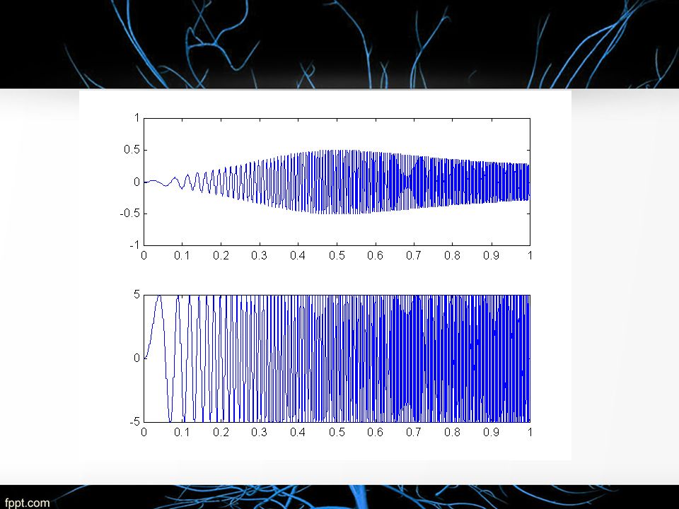
Problem1 : We need to simulate the resonant circuit and display the current waveform as we change the frequency dynamically. v aries from 0 to 2000 rad/s 10 100 uf 0.01 HV(t)=5sinwt Observe the current. What do we expect ? The amplitude of the current waveform will become maximum at resonant frequency, i.e. at = 1000 rad/s
=5sinwt Observe the current. What do we expect . The amplitude of the current waveform will become maximum at resonant frequency, i.e. at = 1000 rad/s.")
8
How to model our resonant circuit ? V(t)=5sin wt 10 100 uf 0.001H Using KVL I
=5sin wt 10 100 uf 0.001H Using KVL I")
9
Differentiate wrt time and re-arrange : Taking Laplace transform :

10
Thus the current can be obtained from the voltage: V I

11
Constructing the model using Simulink: ‘Drag and drop’ block from the Simulink library window to the untitled window

12
Constructing the model using Simulink: TF continous

14
Example in class Show the teacher the output on the scope

15
Problem1:

16
a.Reproduce the same block diagram using simulink. b. From the simulink blockk diagram fing the transfer function both in time and frequency domain

17
Problem 2:

18
Problem3: Find on the internet the transfer function of a power 2 (or higher) low pass filter. a)Define all the parameters and variable b) change the transfer function in time/frequency domain c) Use simulink to analyse the behaviors of the filter bewteen 0<t<5 cycles.
Define all the parameters and variable b) change the transfer function in time/frequency domain c) Use simulink to analyse the behaviors of the filter bewteen 0<t<5 cycles..")
Similar presentations