Download presentation
Presentation is loading. Please wait.

1
Technical Investigation Department

2
METHOD FOR 3-D MODELLING OF A MIXED FLOW PUMP USING PHOENICS D Radosavljevic

3
Introduction Background information on the investigation CFD and PHOENICS role Modelling with PHOENICS Results and analysis Conclusions (simulation, project)
")
4
The Situation A major water supply project located in North Africa (484 pumps). Pumps reported to have been unused when first put into service on this project. The type of pump is defined as a wellpump of the vertical submersible turbine type (7 stages). Pumps were specified to meet a range of duties for 25 years in relation to the envisaged drawdown schedule.
. Pumps were specified to meet a range of duties for 25 years in relation to the envisaged drawdown schedule..")
5
The Situation

6
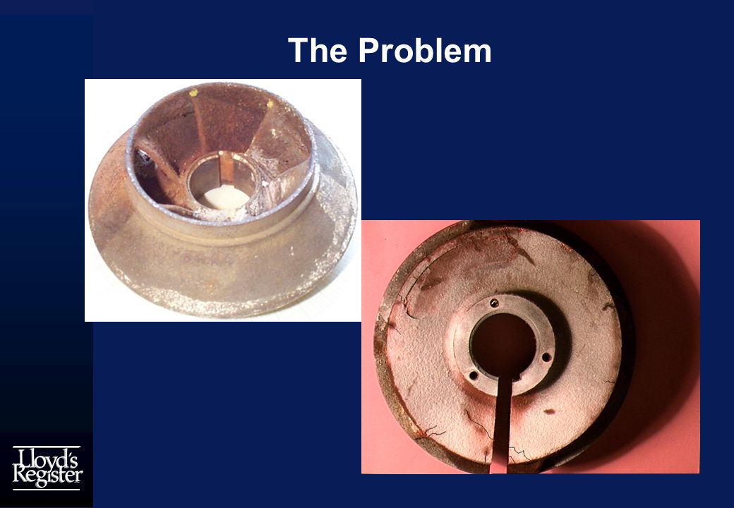
The Problem During the course of approximately 3 years of operation, pump performance problems were encountered in a number of wells. Upon withdrawal from the well, a pump was observed to exhibit severe cracking and corrosion, in particular in the region of the upper pump bowl. Cracking was also observed in the corresponding corroded impeller.

7
The Problem

9
Approach Identifying the nature of the processes involved. The primary ones may be categorised as: - physical (clogging and abrasion); - chemical (clogging and electro- chemical corrosion); - microbial (clogging and microbially- induced corrosion);
; - chemical (clogging and electro- chemical corrosion); - microbial (clogging and microbially- induced corrosion);.")
10
Approach Identifying the nature of the processes involved. Important subsidiary factors: - operational (steady loads (static water head), unsteady loads (water hammer), intermittent pumping and over-abstraction ; - structural and mechanical (design/construction and materials).
, unsteady loads (water hammer), intermittent pumping and over-abstraction ; - structural and mechanical (design/construction and materials)..")
11
Approach A number of separate studies defined including objectives to: determine quasi-steady hydrodynamically-induced loadings, using CFD analysis (PHOENICS); determine other loadings from specification, such as self-weight, torque and centrifugal; apply all loadings to finite element analysis model and determine individual and combined stresses;
; determine other loadings from specification, such as self-weight, torque and centrifugal; apply all loadings to finite element analysis model and determine individual and combined stresses;")
12
Geometry Not supplied (proprietary vane design) Perform sectioning of impeller and the bowl in order to take measurements.
 Perform sectioning of impeller and the bowl in order to take measurements.")
13
Modelling in PHOENICS Model one full stage of the pump as a single device; Apply sliding grid with Multiblock. Rotating block - impeller and stationary block - bowl; Advantage Capture of full transient effects and (true) dynamic loading;
 dynamic loading;.")
14
Modelling in PHOENICS Problems (constraints of sliding MB) no surface porosities allowed (vanes?); only uniform grid in circumferential direction allowed; only clock-wise rotation is allowed (pump rotates anti-clockwise).
 no surface porosities allowed (vanes ); only uniform grid in circumferential direction allowed; only clock-wise rotation is allowed (pump rotates anti-clockwise).")
15
Modelling in PHOENICS Despite all the Problems !

16
Modelling in PHOENICS Compromise approach Treat impeller and the bowl as separate components; Steady simulation of the impeller; Transient simulation of the diffuser with the correct input flow field (impeller exit). (More accurate rotor-stator interaction)
.")
17
Modelling in PHOENICS Impeller modelling Steady; BFC grid; Single passage (1/6 of the flow volume); Cyclic boundary at the exit (vaneless space); 2900 rpm (ROTA patch for rotational forces); Wall friction, k- model; Outlet flow field data saved in a file.
; Cyclic boundary at the exit (vaneless space); 2900 rpm (ROTA patch for rotational forces); Wall friction, k- model; Outlet flow field data saved in a file.")
18
Modelling in PHOENICS Impeller modelling - velocity field

19
Modelling in PHOENICS Stator modelling Transient; Inlet flow field cycles through impeller exit data; BFC grid; Single passage (1/7 of the flow volume); Cyclic boundary at the exit and inlet (vaneless space); Wall friction, k- model.
; Cyclic boundary at the exit and inlet (vaneless space); Wall friction, k- model.")
20
Modelling in PHOENICS Stator modelling - Ground

21
Modelling in PHOENICS Stator modelling - Numerics Convergence generally within 500sw(/tstep); Stator - start from steady solution in aligned position; 10 hours CPU for the transient run;
; Stator - start from steady solution in aligned position; 10 hours CPU for the transient run;")
22
Modelling in PHOENICS Stator modelling - velocity field

23
Modelling in PHOENICS Stator modelling - Assumptions Impeller flow calculated in isolation - no interaction with the stator; Cyclic condition ahead of stator inlet; Assessment of accuracy Pressure increase within impeller 3.6 bar; Pressure increase within stator 2-3 bar; 5.71 bar per stage; Torque 98.7 kW vs. 103kW (GXDRAG).
..")
24
Modelling in PHOENICS Transient pressure field in vaneless space Effect of the impeller blade passing NOTE: Contour scaling at plane values

25
CONCLUSIONS PHOENICS GROUND proved extremely valuable; Allowed extensive modification to the calculation procedure; Pump Obtained estimates of the hydrodynamic loading within the pump; Results do not identify any pronounced local peaks in pressure;

26
CONCLUSIONS

Similar presentations


 in the finite-volume equations.>")


