Download presentation
Presentation is loading. Please wait.

1
Metal Machining Bachelor of Industrial Technology Management with Honours Semester I Session 2013/2014

2
Introduction Mechanics of Cutting Cutting Conditions Chip Formation Types of Cutting Cutting Tool Materials Tool Wear and Tool Life Cutting Fluid Surface Finish TOPIC OUTLINE

3
LESSON OUTCOMES 1.Able to explain the fundamentals of metal cutting 2.Able to select appropriate machining operations for producing products with different specifications

4
INTRODUCTION Classification of Manufacturing Process 1.Primary Processes -Eg.: Casting, Forging, Molding, etc. 2.Secondary Processes -Eg.: Machining 3.Tertiary - Assembly -Eg.: Fabricating like Welding, Brazing, Riveting, etc. 4.Finishing and Surface Treatment – Aesthetic Look -Eg.: Painting, Electroplating, etc.

5
The place of machining operations within the entire production cycle INTRODUCTION

6
Machining is a manufacturing process in which sharp cutting tool is used to cut away material to leave the desired part shape The predominant cutting action in machining involves shear deformation of the work material to form a chip : process of removing unwanted material from a work piece in the form of chips Performed after other processes which provides final shape, more precise dimensions and smooth surface finishes. Material removal process – excess material is removed from a starting work part so that what remains is the desired final geometry MACHINING PROCESS

7
Schematic illustrations of various machining and finishing processes. INTRODUCTION

8
3 Categories: 1.Traditional / Conventional – sharp cutting tool is used to mechanically cut the material to achieve the desired geometry : turning, milling and drilling 2.Abrasive – mechanically remove material by the action of hard, abrasive particles : grinding 3.Non-traditional – use various energy forms include mechanical, electrochemical, thermal & chemical : EDM, CNC etc. MACHINING PROCESS

9
Advantages Variety of work materials Variety of part shapes and geometric features Dimensional accuracy Good surface finishes Disadvantages Wasteful of material Time consuming MACHINING PROCESS

10
MECHANICS OF CUTTING Major independent variables in cutting process Factors influencing the cutting processes: 1.Tool material and coatings 2.Tool shape, surface finish and sharpness 3.Work piece material and condition 4.Cutting speed, feed and depth of cut 5.Cutting fluids & work holding 6.Characteristics of the machine tool Major dependent variables in cutting process Influenced by the changes in the independent variables: 1.Types of chip produced 2.Force and energy distributed during cutting 3.Temperature rise in the work piece, tool and chip 4.Tool wear and failure 5.Surface finish and surface quality of the work piece

11
Problems when machining operations yield unacceptable results such as: 1.Surface finish of the work piece is unacceptable 2.Cutting tool wears rapidly and becomes dull 3.Work piece become very hot 4.Tool begins to vibrate and chatter Require a systematic investigation – study the mechanics of cutting. MECHANICS OF CUTTING

12
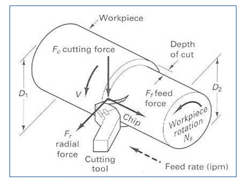
CUTTING CONDITIONS Elements: 1.Cutting speed, V (shown with heavy dark arrow) –The primary cutting motion. –Travelling velocity of the tool relative to the work piece. –Measured in m/s or m/min. 2.Feed, f (shown with dashed arrows) –In turning - amount of material removed per revolution of the work piece and measured in mm/rev –In milling and drilling – amount of material removed per pass of the tool over the work piece and measured in mm/min –To machine a large surface, the tool must be given a feed. 3.Depth of cut, d –The distance the tool is plunged into the surface of the workpiece and measured in mm.
 –In turning - amount of material removed per revolution of the work piece and measured in mm/rev –In milling and drilling – amount of material removed per pass of the tool over the work piece and measured in mm/min –To machine a large surface, the tool must be given a feed. 3.Depth of cut, d –The distance the tool is plunged into the surface of the workpiece and measured in mm..")
14
CHIP FORMATION Diagram shows removal of the deformed material from the work piece by a single point cutting tool. The movement of the tool into the work piece deforms the work material ahead of the tool face plastically and finally separates the deformed material from the work piece. This separated material flows on the rake face of the tool called as chip. The chip near the end of the rake face is lifted away from the tool, and the resultant curvature of the chip is called chip curl.

15
TYPES OF CHIPS 1.Continuous chips - looks like a long ribbon with a smooth and continuous shining surface; resulting in good surface finish, high tool life and low power consumption. 2.Built-up edge - a very hardened layer of work material gradually attached to the tool face; as it grows larger, it becomes unstable and breaks apart, carried away by the tool side and rest on work piece surface. 3.Discontinuous chips - comes off as small chunks or particles; it indicates brittle work material, work piece materials containing hard inclusions and impurities, very low or high cutting speeds, large depth of cut etc. Determined by a number of parameter: 1.Type of tool-work engagement 2.Work material properties 3.Cutting conditions

16
TYPES OF CHIPS

17
TYPES OF CUTTING Principle Types of Cutting: 1.Orthogonal Cutting Cutting edge is straight and is set in a position that is perpendicular to the direction of primary motion and the length of the cutting edge is greater than the width of the chip removed. Known as Two-Dimensional (2-D) Cutting. A few of cutting tools perform orthogonally e.g. lathe cut-off tools, straight milling cutters etc.
 Cutting. A few of cutting tools perform orthogonally e.g. lathe cut-off tools, straight milling cutters etc..")
18
2.Oblique Cutting Cutting edge is set at an angle and inclined to the cutting direction (the tool cutting edge inclination λ s ). Known as Three Dimensional (3-D) Cutting. Majority of the cutting operations perform obliquely such as turning, milling etc. TYPES OF CUTTING
 Cutting. Majority of the cutting operations perform obliquely such as turning, milling etc. TYPES OF CUTTING.")
19
CUTTING TOOL 2 types: 1.Single-point cutting Cutting tool has only one major cutting edge. Eg.: turning, boring. 2.Multipoint cutting Cutting tool has more than one major cutting edge. Eg.: drilling, milling, reaming

20
CUTTING TOOL MATERIALS Must possess properties to avoid excessive wear, fracture failure and high temperatures in cutting. Required characteristics: 1.Hardness at elevated temperatures (so-called hot hardness) - so that hardness and strength of the tool edge are maintained in high cutting temperatures.
 - so that hardness and strength of the tool edge are maintained in high cutting temperatures..")
21
2.Toughness - ability of the material to absorb energy without failing. 3.Wear resistance - depends on hot hardness, surface finish on the tool, chemical inertness and thermal conductivity of the tool material. Types: 1.Carbon steels 2.High-speed steel 3.Cemented carbides 4.Ceramics 5.Cubic Boron Nitride (CBN) 6.Synthetic Diamonds CUTTING TOOL MATERIALS
 6.Synthetic Diamonds CUTTING TOOL MATERIALS.")
22
TOOL WEAR AND TOOL LIFE Categories of tool wear: 1.Gradual wearing of certain regions of the face and flank of the cutting tool 2.Abrupt tool failure Options of resolving tool wear: 1.Re-sharpen the tool on a tool grinder, or 2.Replace the tool with a new one and applied when: a.Resource for tool resharpening is exhausted b.Tool does not allow for resharpening

23
Parameters which affect the rate of tool wear: 1.Cutting conditions (cutting speed V, feed f, depth of cut d) 2.Cutting tool geometry (tool orthogonal rake angle) 3.Cutting fluids Measures to reduce the tool wear: 1.Appropriate setting of cutting conditions 2.Application of advance cutting tool materials (coated carbide, ceramics) 3.Use of cutting fluid TOOL WEAR AND TOOL LIFE
 2.Cutting tool geometry (tool orthogonal rake angle) 3.Cutting fluids Measures to reduce the tool wear: 1.Appropriate setting of cutting conditions 2.Application of advance cutting tool materials (coated carbide, ceramics) 3.Use of cutting fluid TOOL WEAR AND TOOL LIFE")
24
CUTTING FLUID Any liquid or gas that is applied to the chip and/or cutting tool to improve cutting performance. Main functions: 1.Remove heat in cutting Depends on the method of application, type of the cutting fluid and the fluid flow rate and pressure. 2.Lubricate the chip-tool interface Cutting fluids penetrate the tool-chip interface and reducing the friction forces and temperatures. 3.Wash away chips Applicable to small, discontinuous chips only. Special devices are subsequently needed to separate chips from cutting fluids. Types: 1.Cutting oils 2.Soluble oils 3.Chemical fluids

25
Schematic illustration of the methods of applying cutting fluids (by flooding) in various machining operations: (a) turning, (b) milling, (c) thread grinding, and (d) drilling. CUTTING FLUID

26
SURFACE FINISH Machining processes generate a wide variety of surface textures. Types of surface texture: 1.Roughness - small, finely spaced surface irregularities (micro irregularities) 2.Waviness - surface irregularities of grater spacing (macro irregularities) 3.Lay - predominant direction of surface texture
 2.Waviness - surface irregularities of grater spacing (macro irregularities) 3.Lay - predominant direction of surface texture.")
27
Factors influencing surface roughness: 1.Tool geometry (major cutting edge angle and tool corner radius) - Increasing the tool rake angle improves surface finish. 2.Cutting conditions (cutting velocity and feed) - High speed and low feed provide best surface finish. 3.Work material properties (hardness) - Higher work material hardness results in better surface finish. - Tool material has minor effect on surface finish. 4.Cutting fluid - Cutting fluids affect the surface finish by changing cutting temperature. SURFACE FINISH
 - High speed and low feed provide best surface finish. 3.Work material properties (hardness) - Higher work material hardness results in better surface finish. - Tool material has minor effect on surface finish. 4.Cutting fluid - Cutting fluids affect the surface finish by changing cutting temperature. SURFACE FINISH.")
Similar presentations