Download presentation
Presentation is loading. Please wait.

1
College of Engineering Non-uniform Grid- based Coordinated Routing Priyanka Kadiyala Major Advisor: Dr. Robert Akl Department of Computer Science and Engineering Priyanka Kadiyala Major Advisor: Dr. Robert Akl Department of Computer Science and Engineering

2
Outline Research objective Overview of sensor networks Related work Motivation Non-uniform grid-based coordinated routing protocol Simulations and results Research objective Overview of sensor networks Related work Motivation Non-uniform grid-based coordinated routing protocol Simulations and results 10/2/2015

3
Overview of Sensor Networks Ad hoc networks of tiny battery powered sensor nodes capable of sensing, processing and communicating data. Applications - Video surveillance, traffic monitoring, environmental monitoring, structure and system health monitoring in buildings and aircraft interiors. The main source of energy is battery, no external supply of power - major constraint is energy available. Ad hoc networks of tiny battery powered sensor nodes capable of sensing, processing and communicating data. Applications - Video surveillance, traffic monitoring, environmental monitoring, structure and system health monitoring in buildings and aircraft interiors. The main source of energy is battery, no external supply of power - major constraint is energy available. 10/2/2015

4
Research Objective To increase the lifetime of the sensor network by using non-uniform grid based routing for the case of random node deployment. To increase the lifetime of the sensor network by using non-uniform grid based routing for the case of random node deployment. 10/2/2015

5
Overview of Sensor Networks Routing Protocols Table-driven routing protocols Rely on routing tables, hence require continuous updating of the routing table. On-demand routing protocols Do not maintain routing tables, but use a procedure to identify a route as and when a source requires to transmit information to a destination 10/2/2015

6
Overview of Sensor Networks Protocols for WSNs Flooding, Gossiping, SPIN, LEACH, PEGASIS, Directed Diffusion, and GEAR Energy efficient protocols that allow nodes to be put to sleep are GAF, SPAN, STEM, ASCENT, CEC, AFECA and GBCR. Protocols for WSNs Flooding, Gossiping, SPIN, LEACH, PEGASIS, Directed Diffusion, and GEAR Energy efficient protocols that allow nodes to be put to sleep are GAF, SPAN, STEM, ASCENT, CEC, AFECA and GBCR. 10/2/2015

7
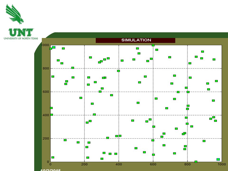
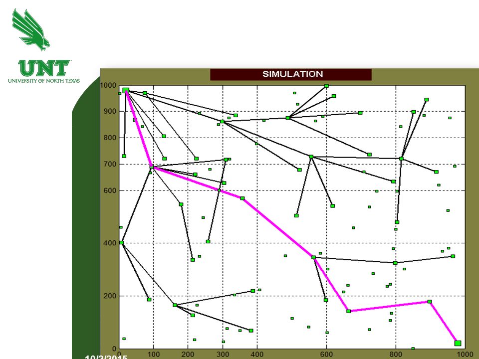
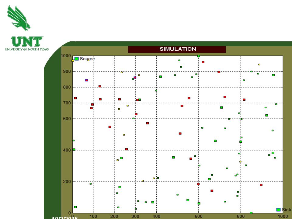
Related Work Flooding : In flooding every node that receives a packet broadcasts it to its neighbors. If the node receives the packet for the first time, it is stored in the buffer. If it is a redundant packet, it is discarded. Flooding : In flooding every node that receives a packet broadcasts it to its neighbors. If the node receives the packet for the first time, it is stored in the buffer. If it is a redundant packet, it is discarded. 10/2/2015

8
Flooding Simulation 10/2/2015

9
Related Work Geographic Adaptive Fidelity: A virtual grid is proposed with only one node active at a time in each grid. Other nodes save energy by turning their radios off, or by entering sleep mode. Each node in GAF has three states: sleeping, discovery and active states respectively. Geographic Adaptive Fidelity: A virtual grid is proposed with only one node active at a time in each grid. Other nodes save energy by turning their radios off, or by entering sleep mode. Each node in GAF has three states: sleeping, discovery and active states respectively. 10/2/2015

10
Related Work Span: Forms a backbone network of active nodes that participate in routing. A node in Span can only be in two states: coordinator and a non-coordinator. A node volunteers to be the coordinator if two of its neighbors fail to communicate with each other, either directly or through another coordinator. Span: Forms a backbone network of active nodes that participate in routing. A node in Span can only be in two states: coordinator and a non-coordinator. A node volunteers to be the coordinator if two of its neighbors fail to communicate with each other, either directly or through another coordinator. 10/2/2015

11
Related Work Grid-based Coordinated Routing: Combines flooding, GAF and Span. Network is partitioned into square shaped grids. In each grid, one node participates in routing while other nodes are put to sleep to conserve energy. Grid-based Coordinated Routing: Combines flooding, GAF and Span. Network is partitioned into square shaped grids. In each grid, one node participates in routing while other nodes are put to sleep to conserve energy. 10/2/2015

15
Motivation To save energy by radio range adjustment, dividing the network into sections of different grid sizes based on a range-traffic relationship has been proposed. Our work is motivated from the concept of non-uniform grid sizes across the network using coordinated routing. To save energy by radio range adjustment, dividing the network into sections of different grid sizes based on a range-traffic relationship has been proposed. Our work is motivated from the concept of non-uniform grid sizes across the network using coordinated routing. 10/2/2015

16
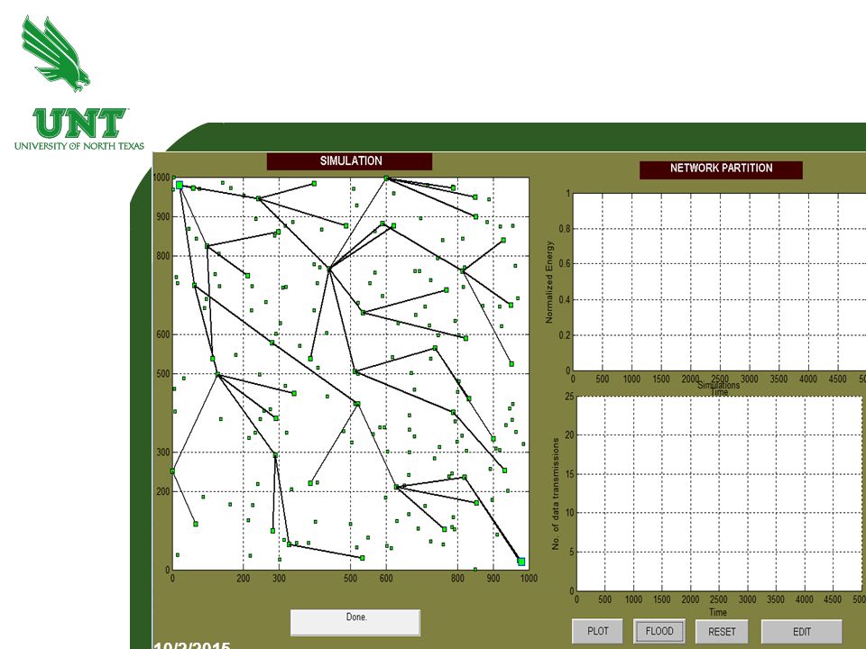
Non-uniform Grid-based Coordinated Routing Protocol The entire test area is divided into grids. Estimate the grid size to ensure proper connectivity between two coordinator nodes in adjacent grids. A coordinator node is elected in each grid to participate in routing. Energy depletion of nodes is taken into account for load balancing in the network. The entire test area is divided into grids. Estimate the grid size to ensure proper connectivity between two coordinator nodes in adjacent grids. A coordinator node is elected in each grid to participate in routing. Energy depletion of nodes is taken into account for load balancing in the network. 10/2/2015

17
Estimating the Grid Size To ensure connectivity and efficient usage of node energy, the grid size should neither be too large nor too small. 10/2/2015

18
Estimating the Grid Size (Contd.) The amount of energy that is required to establish a link between two nodes is proportional to the distance between the two nodes raised to a constant power, called the path loss exponent, n. If S is the receiver sensitivity, the communication link between the two nodes leads to a successful transmission between the nodes if the power of the received signal is greater than S. The amount of energy that is required to establish a link between two nodes is proportional to the distance between the two nodes raised to a constant power, called the path loss exponent, n. If S is the receiver sensitivity, the communication link between the two nodes leads to a successful transmission between the nodes if the power of the received signal is greater than S. 10/2/2015

19
RnRn r 2r Estimating the Grid Size (Contd.) We define an upper bound on the grid size as 200 m and consider a lower bound of 100 m. 10/2/2015

20
Non-uniform grid structures Designing the grid structures: Areas of high node density can be used efficiently for a grid size of 200 m. Areas of low node density require a grid size of 100 m. Random node placement implies sparsely and densely populated areas, therefore requiring a non-uniform distribution of grid size. Designing the grid structures: Areas of high node density can be used efficiently for a grid size of 200 m. Areas of low node density require a grid size of 100 m. Random node placement implies sparsely and densely populated areas, therefore requiring a non-uniform distribution of grid size. 10/2/2015

21
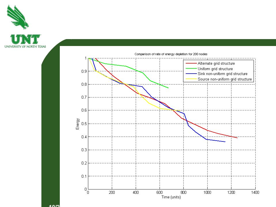
Types of non-uniform grids Source non-uniform grid structure : suitable for low density around the source node and high density around sink node. Sink non-uniform grid structure : suitable for high density around the source node and low density around the sink node. Alternating non-uniform grid structure : suitable for random node placement across the network. Source non-uniform grid structure : suitable for low density around the source node and high density around sink node. Sink non-uniform grid structure : suitable for high density around the source node and low density around the sink node. Alternating non-uniform grid structure : suitable for random node placement across the network. 10/2/2015

22
Source non-uniform grid structure 10/2/2015

23
Sink non-uniform grid structure 10/2/2015

24
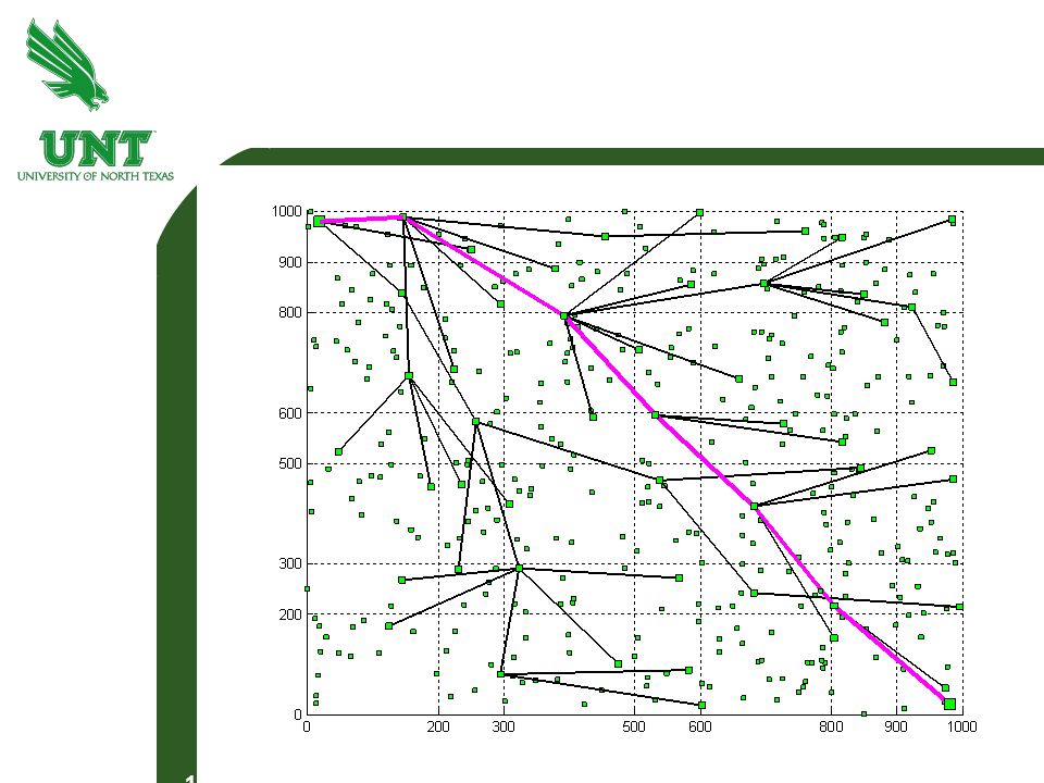
Alternating non-uniform grid structure 10/2/2015

25
Coordinator node election Each node has a randomly assigned ID. From each grid, the node with maximum node ID is the coordinator node. To distribute load across the coordinator nodes in a fair manner, load balancing is employed. Each node has a randomly assigned ID. From each grid, the node with maximum node ID is the coordinator node. To distribute load across the coordinator nodes in a fair manner, load balancing is employed. 10/2/2015

26
Load Balancing If coordinator node energy > 25% of battery life, node rank = node rank +1 If the energy < 25% of battery life, node rank = node rank + 2 For each grid, the current coordinators are replaced with lower ranked nodes. If coordinator node energy > 25% of battery life, node rank = node rank +1 If the energy < 25% of battery life, node rank = node rank + 2 For each grid, the current coordinators are replaced with lower ranked nodes. 10/2/2015

29
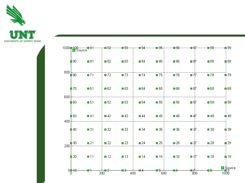
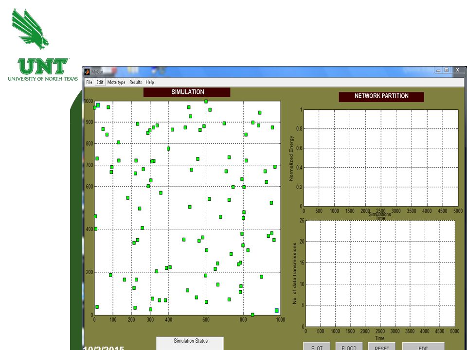
Simulations and results Assumptions: Energy consumption by nodes is assumed as Idle:transmit:receive = 1:2:1.5 Test area is assumed to be replicating an actual sensor field of size 1000 m in the x-direction and 1000 m in the y-direction. Position of nodes deployed is assumed to be the same for all grid structures. Assumptions: Energy consumption by nodes is assumed as Idle:transmit:receive = 1:2:1.5 Test area is assumed to be replicating an actual sensor field of size 1000 m in the x-direction and 1000 m in the y-direction. Position of nodes deployed is assumed to be the same for all grid structures. 10/2/2015

32
Network Parameters 10/2/2015

33
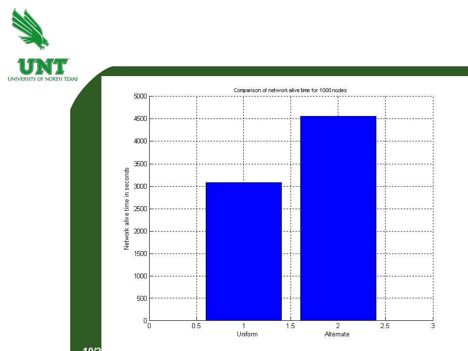
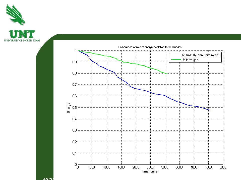
Results Metrics: Normalized energy Network lifetime Graphs: Network lifetime graph. Energy depletion graph. Metrics: Normalized energy Network lifetime Graphs: Network lifetime graph. Energy depletion graph. 10/2/2015

34
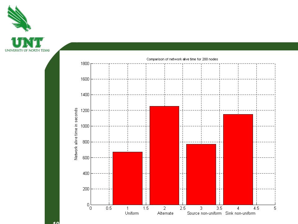
Network Lifetime Graph 10/2/2015

37
Energy Depletion Graph 10/2/2015

40
Node density Lifetime for Uniform grid structure (seconds) Lifetime for Alternating non – uniform grid structure (seconds) Lifetime for Source non- uniform grid (seconds) Lifetime for Sink non- uniform grid (seconds) 100 nodes 600 880 550 800 200 nodes 680 1250 780 1170 400 nodes 1800 1840 1660 1250 1000 nodes 3000 4500 4000 4300
 Lifetime for Alternating non – uniform grid structure (seconds) Lifetime for Source non- uniform grid (seconds) Lifetime for Sink non- uniform grid (seconds) 100 nodes nodes nodes nodes")
41
Conclusion Different non-uniform grid structures provide different levels of energy savings and network lifetime. For random node deployment, using a non-uniform grid structure of alternating small and large grid size improves network lifetime over a uniform grid structure. Different non-uniform grid structures provide different levels of energy savings and network lifetime. For random node deployment, using a non-uniform grid structure of alternating small and large grid size improves network lifetime over a uniform grid structure. 10/2/2015

43
Future Work Implementation on actual motes. Mobility of nodes. Irregular distribution of nodes. Implementation on actual motes. Mobility of nodes. Irregular distribution of nodes. 10/2/2015

44
Thank you Questions ? 10/2/2015

Similar presentations


 Presented by Yi Cheng Lin.>")


