Download presentation
Presentation is loading. Please wait.

1
Magnetism Intro

2
Magnets About three thousand years ago, the Greeks discovered rocks which would attract iron or similar rocks (a mineral ore we call magnetite). They were found in Magnesia, an area in Asia Minor
. They were found in Magnesia, an area in Asia Minor")
3
Lodestones The Chinese later used these naturally occurring magnets, called lodestones, for ocean navigation. The first recorded description of a compass was in the Chinese Book Dream Pool Essays (1086) by Shen Kuo in the Song Dynasty, about 100 years earlier than its first record in Europe by Alexander Neekam in 1190. Source:
 by Shen Kuo in the Song Dynasty, about 100 years earlier than its first record in Europe by Alexander Neekam in Source:")
4
Magnets William Gilbert (a physician to Queen Elizabeth I) made many discoveries about magnets – including that the Earth itself is a giant magnetic sphere! He also discovered that he could make his own magnets, and coined the term “magnetic pole”.
 made many discoveries about magnets – including that the Earth itself is a giant magnetic sphere! He also discovered that he could make his own magnets, and coined the term magnetic pole .")
5
Magnets Magnetism is caused by the
Magnets Magnetism is caused by the movement of electrons within an atom. Magnets are surrounded by magnetic fields Electrons produce magnetic fields because they orbit the nucleus spin on their own axis.

6
!!! Chemistry Flashback !!! Electrons pair up two per orbital – one spins clockwise, the other counter clockwise. Direction of spin determines the “pole” of the electron. Diamagnetic materials – have paired electrons where the fields cancel out because all the electrons are in pairs and have opposite spins. Material will be repelled by a magnetic field (weak effect). (1/1,000,000 weaker than iron). The electric fields required to levitate these materials are extremely large. Source: Magnetic Frog
. (1/1,000,000 weaker than iron). The electric fields required to levitate. these materials are extremely large. Source: Magnetic Frog.")
7
Paramagnetic materials - have unpaired electrons.
!!! Chemistry Flashback !!! Paramagnetic materials - have unpaired electrons. Iron (Fe) electron configuration 4 s2 3 d6 In d cloud electrons occupy 5 orbitals. Auf bau principle – electrons must enter an empty orbital before they pair up. The magnetic fields of the unpaired electrons combine to make each Fe atom a tiny magnet.
 electron configuration 4 s2 3 d6. In d cloud electrons occupy 5 orbitals. Auf bau principle – electrons must enter an empty orbital before they pair up. The magnetic fields of the unpaired electrons combine to make each Fe atom a tiny magnet.")
8
But not all iron is magnetic…right? Why not?
The unpaired electrons give areas in these elements small magnetic fields. When the individual areas or domains all line up, the piece of metal has a BIG magnetic field

9
Magnetic Materials Ferromagnetic – an element which is
Magnetic Materials Ferromagnetic – an element which is attracted to magnets and can be made into temporary magnets. Iron, nickel and cobalt. All are paramagnetic elements

10
http://www. physics. carleton
Magnetic Materials Hard magnetic materials - require a strong external magnetic field to orient their domains. Once oriented the domains stay aligned. Permanent magnets Alnico, an alloy of aluminum, nickel, cobalt, iron and copper common permanent magnet. Heating or hitting can move the domains out of alignment Soft magnetic materials (nails & paper clips) are easily magnetized but demagnetized when the external field is removed. Domains become random again when the magnet is removed. Temporary magnetism
 are easily magnetized but demagnetized when the external field is removed. Domains become random again when. the magnet is removed. Temporary magnetism.")
11
Magnetic Poles Magnets have polarity (different parts of a magnet experience different forces) Poles of a magnet are called north and south Opposite poles attract, like poles repel. Magnetic poles always come in pairs (north and south) not possible to have only one pole Magnetic dipole. Breaking a magnet in half forms two new magnets.
 not possible to have only one pole. Magnetic dipole. Breaking a magnet in half forms two new magnets.")
12
Cutnell & Johnson, Wiley Publishing, Physics 5th Ed.
Magnetic Field The space around a magnet has an invisible magnetic field that exerts magnetic forces This field is represented by drawing magnetic field lines or lines of magnetic flux Greater magnetic flux density (stronger field) is shown with more flux lines closer lines stronger the magnetic field. the flux density is the greatest at the POLES! arrows show the direction (out of the north pole and into the south pole) pass through the magnet to form loops. Cutnell & Johnson, Wiley Publishing, Physics 5th Ed. Earth’s Field
 is shown with more flux lines. closer lines stronger the magnetic field. the flux density is the greatest at the POLES! arrows show the direction (out of the north pole and into the south pole) pass through the magnet to form loops. Cutnell & Johnson, Wiley Publishing, Physics 5th Ed. Earth’s Field.")
13
Drawing Magnetic Fields
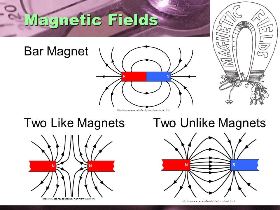
Compass Method If we could scatter tiny compass needles over a piece of paper and bring a bar magnet underneath them, the needles would line up in the bar magnet’s magnetic field Iron Filing Method Sprinkling iron files near a magnet will cause the filings to line up along the magnetic flux lines Cutnell & Johnson, Wiley Publishing, Physics 5th Ed.

14
Magnetic Fields Bar Magnet Two Like Magnets Two Unlike Magnets
15
Magnetic Field Between two like poles.

16
Magnetic Field Between two opposite poles.

17
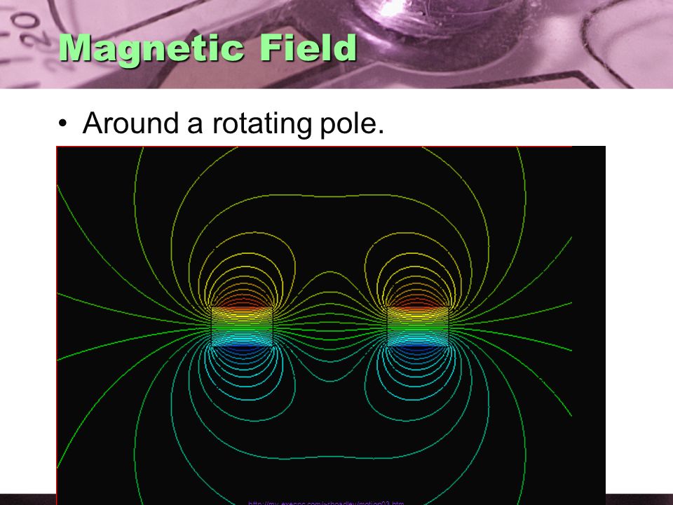
Magnetic Field Around a rotating pole.
18
Magnetic Field Field Variations.

19
Earth’s Magnetism The earth has a magnetic field!
Earth’s Magnetism The earth has a magnetic field! Scientists theorize it is caused by electric currents circulating in the liquid outer core. The earth has both a north and a south magnetic pole, like a magnet. Notice the earth’s magnetic field lines! Same shape as a bar magnet Is the Earth’s North Pole a North or a South magnetic pole? Cutnell & Johnson, Wiley Publishing, Physics 5th Ed.

20
Compass If suspended, a magnet’s north pole will point toward the earth’s geographic north. A compass is a magnetic needle on a pivot. Cutnell & Johnson, Wiley Publishing, Physics 5th Ed.

21
North Pole Fallacy Is the Earth’s North Pole a North or South magnetic pole? You already know that like poles _______and that unlike poles _______. But think about this… The north end of a magnet is attracted to the south end of a second magnet. The north end of a compass needle points to the geographic NORTH pole of the earth…. So…the earth’s geographic NORTH pole must be a magnetic SOUTH pole. Cutnell & Johnson, Wiley Publishing, Physics 5th Ed.

22
Earth’s Magnetic Field
Since the earth is tilted, the magnetic poles of the earth don’t line up exactly with the geographic poles. This discrepancy is called magnetic declination. Angle of declination Copywrited by Holt, Rinehart, & Winston

23
Importance of Earth’s Magnetic Field
Navigation Animal migration Navigational systems Protects the earth from solar winds Charged particles from the sun Aurora Borealis – Northern Light Aurora Australis – Southern Lights Earth’s Core

24
Earth’s Magnetic Field
Earth’s Magnetic Field Over the past 150 years, the main component of the Earth's magnetic field has decayed by nearly 10%, a rate ten times faster than expected This is centered around an area in the south Atlantic Ocean that has a field 35% weaker than expected. source: Earth’s Magnetic Field

25
Are Magnetism and Electricity Connected?
Until 1820 everyone thought electricity and magnetism were completely separate. Hans Oersted discovered that a compass needle is deflected by an electric current. Electricity and Magnetism are just different aspects of the same thing! Oersted – Dutch teacher. Demonstrating that magnetism and electricity not connected. Student after class switched direction of the wire.

26
Magnetic Field Generation
Moving charges create magnetic fields. The magnetic field of a current through a straight wire makes circles perpendicular to the current.

27
Magnetic Field Generation
Copywrited by Holt, Rinehart, & Winston Cutnell & Johnson, Wiley Publishing, Physics 5th Ed.

28
Right Hand Rule (Grip Rule)
Cutnell & Johnson, Wiley Publishing, Physics 5th Ed. Copywrited by Holt, Rinehart, & Winston To calculate the direction of the magnetic field produced by a current carrying wire: Point your right thumb in the direction of the conventional current flow. Your fingers curl in the direction of the magnetic field. Current Convention:

29
RHR Practice What direction would the magnetic field be around a current coming out of the screen? A. Clockwise B. Counterclockwise C. Into the screen D. Out of the screen

30
Checking Understanding
The magnetic field of a straight, current- carrying wire is parallel to the wire. perpendicular to the wire. around the wire. inside the wire. zero. Answer: C Slide 24-4

31
Checking Understanding
Point P is 5 cm above the wire as you look straight down at it. In which direction is the magnetic field at P? Answer: D Slide 24-19

32
Checking Understanding
Point P is 5 cm above the wire as you look straight down at it. In which direction is the magnetic field at P? Answer: D Slide 24-20

33
Magnetic Force A charge moving in a magnetic field feels a force.
The force on the charge is a “sideways” force - perpendicular to the field line and to the charge’s velocity.

34
Magnetic Force Charge not moving? Charge moving with field line?
Cutnell & Johnson, Wiley Publishing, Physics 5th Ed. Magnetic Force Charge not moving? Charge moving with field line? The charge must move ACROSS the field lines to feel a force NO FORCE

35
Magnetic Force Experiments show that: F ~ the current, I
Cutnell & Johnson, Wiley Publishing, Physics 5th Ed. Magnetic Force Experiments show that: F ~ the current, I F ~ the length of conductor in the field, F = (a constant) I x the constant is called the magnetic flux density (B) when current flows at 90° to the field. B is a measure of the strength of the magnetic field B units are NA-1m-1 or Teslas (T)
 I x. the constant is called the magnetic flux density (B) when current flows at 90° to the field. B is a measure of the strength of the magnetic field. B units are NA-1m-1 or Teslas (T)")
36
Magnetic Force Flux density is the force per unit
Cutnell & Johnson, Wiley Publishing, Physics 5th Ed. Magnetic Force Flux density is the force per unit length acting on a conductor placed at 90° to the field. If the conductor is placed at an angle θ to the field, then the force is given by:

37
Right Hand Rule (Slap Rule)

38
Magnetic Force on a Wire
Checking Understanding Magnetic Force on a Wire A horizontal wire carries a current and is in a vertical magnetic field. What is the direction of the force on the wire? 1) left 2) right 3) zero 4) into the page 5) out of the page I B
 left. 2) right. 3) zero. 4) into the page. 5) out of the page. I. B.")
39
Magnetic Force on a Wire
Checking Understanding Magnetic Force on a Wire 1) left 2) right 3) zero 4) into the page 5) out of the page A horizontal wire carries a current and is in a vertical magnetic field. What is the direction of the force on the wire? B I
 left. 2) right. 3) zero. 4) into the page. 5) out of the page. A horizontal wire carries a current and is in a vertical magnetic field. What is the direction of the force on the wire B. I.")
40
Magnetic Force on a Charge
On average, the charges must be moving with speed v = /t. Therefore, If the direction of the velocity is not at 90° to the flux lines, we use the component of the velocity which acts at 90° to the field. and the direction of the force is at 90° (perpendicular) to both the velocity and the magnetic field. Consider a conductor of length, having n free electrons per unit volume. A current, I, is flowing through it. Recall, and This is the sum of the forces acting on all the free charges as they move through the piece of conductor. Therefore, force per charge, F, is given by Charged Particle in a Magnetic Field
 to both the velocity and the magnetic field. Consider a conductor of length, having n free electrons per unit volume. A current, I, is flowing through it. Recall, and. This is the sum of the forces acting on all the free charges as they move through the piece of conductor. Therefore, force per charge, F, is given by. Charged Particle in a. Magnetic Field.")
41
Right Hand Rule (Slap Rule)
The direction of the magnetic field can be determined using the right hand rule. Cutnell & Johnson, Wiley Publishing, Physics 5th Ed. Force direction calculation Thumb direction of (+) charge Point fingers in the direction of the magnetic field The palm indicates the direction of force Alternative method Is there a left hand rule? Yes, when a (–) charge is involved Copywrited by Holt, Rinehart, & Winston
 charge. Point fingers in the direction. of the magnetic field. The palm indicates the direction of force. Alternative method. Is there a left hand rule Yes, when a (–) charge is involved. Copywrited by Holt, Rinehart, & Winston.")
42
What direction? A positive charge moving with a constant velocity enters a uniform magnetic field pointing out of the paper. What way will the charge move? Continue straight Curve upward Curve downward Go into the paper What would have happened if it was a negative charge moving into a magnetic field pointing into the paper? Cutnell & Johnson, Wiley Publishing, Physics 5th Ed.

43
Checking Understanding
Magnetic Force A positive charge enters a uniform magnetic field as shown. What is the direction of the magnetic force? 1) out of the page 2) into the page 3) downward 4) to the right 5) to the left x x x x x x v q
 out of the page. 2) into the page. 3) downward. 4) to the right. 5) to the left. x x x x x x. v. q.")
44
Checking Understanding
Magnetic Force A positive charge enters a uniform magnetic field as shown. What is the direction of the magnetic force? 1) out of the page 2) into the page 3) downward 4) upward 5) to the left x x x x x x v q
 out of the page. 2) into the page. 3) downward. 4) upward. 5) to the left. x x x x x x. v. q.")
45
Checking Understanding
Magnetic Force A positive charge enters a uniform magnetic field as shown. What is the direction of the magnetic force? 1) out of the page 2) into the page 3) zero 4) to the right 5) to the left ® ® ® ® ® v q
 out of the page. 2) into the page. 3) zero. 4) to the right. 5) to the left. ® ® ® ® ® v. q.")
46
Charge Paths in a Magnetic Field
Cutnell & Johnson, Wiley Publishing, Physics 5th Ed. Three possible paths followed by a charged particle moving through a uniform magnetic field: if q = zero the path is a straight line if q = 90° the path is circular if 0 < q < 90° the path is a helix. Cutnell & Johnson, Wiley Publishing, Physics 5th Ed. Cutnell & Johnson, Wiley Publishing, Physics 5th Ed.

47
Flux Density due to Current Flowing in a Long, Straight Wire
The flux density, B, at point p is directed out of the plane of the diagram. The magnitude of B depends on The current, I The perpendicular distance, r The medium in the space around the wire Assumption: if r is small compared with the length of wire, then B does not depend on the length of the wire. Therefore, where µ is the permeability of the medium µo represents air or a vacuum and has units of NA-2 or Henrys per meter (Hm-1).
.")
48
Force per Unit Length between Two Long Parallel Conductors Carrying Current
Flux density, B, near conductor 2 due to I1 is So, the force (F=I B) which acts on length of conductor 2 is given by Therefore, the force per unit length is given by Also, by Newton’s third law we can say that there is an equal but opposite force acting on conductor 1. Now, if F/ .= 2 × 10⁻⁷ Nm-1 and r = 1m and I1 = I2, then the current in each conductor is 1 Amp. Derivation source:
 which acts on length of conductor 2 is given by. Therefore, the force per unit length is given by. Also, by Newton’s third law we can say that there is an equal but opposite force acting on conductor 1. Now, if F/ .= 2 × 10⁻⁷ Nm-1 and r = 1m and I1 = I2, then the current in each conductor is 1 Amp. Derivation source:")
49
Formal Amp Definition One Amp is that current which, when flowing in each of two straight, parallel, infinitely long wires, separated by 1m, in a vacuum, produces a force per unit of 2 ×10⁻⁷Nm-1.

50
Attraction or Repulsion
What will happen if two long parallel wires are carrying currents, I1 and I2, flowing in the same direction are placed next to each other? They attract each other They repel each other No interaction Copywrited by Holt, Rinehart, & Winston Copywrited by Holt, Rinehart, & Winston Cutnell & Johnson, Wiley Publishing, Physics 5th Ed.

51
Attraction or Repulsion
What will happen if two long parallel wires are carrying currents, I1 and I2, flowing in the opposite direction are placed next to each other? They attract each other They repel each other No interaction Copywrited by Holt, Rinehart, & Winston Cutnell & Johnson, Wiley Publishing, Physics 5th Ed.

52
Flux Density inside a Long Coil (Solenoid)
Current flowing through a conductor produces a magnetic field. For a long straight wire, then the field is distributed over a large region of space. If the wire is used to make a coil, the magnetic field is concentrated into a smaller space and is therefore stronger. Cutnell & Johnson, Wiley Publishing, Physics 5th Ed.

53
Wire Loop Bending a current carrying wire into a circle gives a magnetic field like this: Cutnell & Johnson, Wiley Publishing, Physics 5th Ed.

54
Solenoid Cutnell & Johnson, Wiley Publishing, Physics 5th Ed. Winding many turns makes a solenoid coil with a magnetic field like a bar magnet.

55
Right Hand Rule (Coil Rule)
")
56
Checking Understanding
Current Loop What is the direction of the magnetic field at the center (point P) of the square loop of current? 1) left 2) right 3) zero 4) into the page 5) out of the page P I
 of the square loop of current 1) left. 2) right. 3) zero. 4) into the page. 5) out of the page. P. I.")
57
Magnetic Strength of a Coil
Theory suggests that the flux density, Bc, at the center of a long coil, is Where N = # of turns = length Measurements shows that if the solenoid’s length ≥ 10 times its diameter, the flux density inside is uniform over most of its length. The graph shows the variation of B along the axis of a long solenoid.

58
Electromagnet A coil of wire with a current passing through it creates a magnetic field just like a bar magnet. Can be turned on/off or reversed by controlling the current flow.

59
Electromagnet How can you strengthen an electromagnet?
Putting an iron core in the center of the coil strengthens the magnetic field. Adding more coils makes the magnetic field stronger. Increasing the current through the wire strengthens the magnetic field.

60
Simple Electric Motors
A coil, with current flowing through it, placed in a magnetic field, can experience a torque. When a current-carrying loop is placed in a magnetic field, the loop tends to rotate such that its normal becomes aligned with the magnetic field. Cutnell & Johnson, Wiley Publishing, Physics 5th Ed. Cutnell & Johnson, Wiley Publishing, Physics 5th Ed.

61
Simple Electric Motors
Cutnell & Johnson, Wiley Publishing, Physics 5th Ed. Simple Electric Motors Torque (τ): magnitude of the torque ~ I depends on the angle, θ, between the field and the coil. Torque ~ sin θ τ =F x d for a loop of wire d = w/2 sinΦ where w = width of the loop Φ is the angle between the normal to the plane of the loop and the direction of the magnetic field. Net torque = τ = ILB(1/2 w sin Φ) + ILB(1/2 w sin Φ) = IAB sin Φ Wire is wrapped to form a loop of N loops t = NIABsinf
: magnitude of the torque ~ I. depends on the angle, θ, between the field and the coil. Torque ~ sin θ. τ =F x d for a loop of wire. d = w/2 sinΦ. where w = width of the loop. Φ is the angle between the normal to the plane of the loop and the direction of the magnetic field. Net torque = τ = ILB(1/2 w sin Φ) + ILB(1/2 w sin Φ) = IAB sin Φ. Wire is wrapped to form a loop of N loops. t = NIABsinf.")
62
Simple Electric Motors
A simple d.c. electric motor consists of a coil of wire placed in a magnetic field. When current flows through the coil, a torque is produced. The brushes and commutator conduct the current from the supply to the coil. Each of the carbon brushes makes contact with one half of the commutator. The commutator rotates with the coil. This arrangement ensures that the torque produces a constant sense of rotation. Copywrited by Holt, Rinehart, & Winston

63
Simple Electric Motors
In the diagram below, the force on side a – b of the coil will be directed downwards so the rotation is counter-clockwise (viewed from the front). When the coil has rotated 180°, side d – c is on the left but, as the commutator has also rotated, the torque is still in the same sense. DC Motors
. When the coil has rotated 180°, side d – c is on the left but, as the commutator has also rotated, the torque is still in the same sense. DC Motors.")
64
Simple Electric Motors

65
Simple Electric Motors

66
Simple Electric Motors

67
Simple Electric Motors

68
Simple Electric Motors

69
Magnetic Flux If B is at 90° to the area, A, then the total magnetic flux, Φ "passing through" A is defined to be Φ greek letter phi The units of flux are Tm² 1 Tm² = 1 Weber If B is not at 90° to the area: the component of B which acts at 90° to A is B cos α. So, the flux passing through the area is f = AB

70
Flux Linkage a flux, Φ, "passes through" a coil of N turns then the coil is said to be linked to the flux so we define the quantity "flux linkage" as N = # of turns, B = magnetic field strength A = cross sectional area of coil θ = angle to normal of coil Associated with a multiple turned coil or solenoid Flux linkage = # of turns x magnetic flux Φ = NBA cosθ

71
Can a Magnetic Field produce a Current?
For 12 years after Oersted’s discovery that electric current creates a magnetic field, scientists looked for a way for magnetic fields to create a current. In 1832, Michael Faraday made a suggestion: “Move the Magnet!” Doing so “induced” an electric current!!!! The result of Faraday’s work became known as electromagnetic induction.

72
Electromagnetic Induction
Thrusting a magnet into a loop of wire induces current. Holding the magnet still does not! It doesn’t matter whether the magnetic field moves or the wire moves. It works either way! Faraday described this by saying that electromotive forces are generated in the wire whenever field lines cut across the wire. When the magnet is thrust into the loop, its field lines cut across the wire generating EMF that produces current. Ditto when the loop is moved over the magnet.

73
EMF Clarification Warning: The term EMF can be misleading!!!!!
The electromotive forces that are generated are not really “forces”. They are actually increases in electrical potential (voltage) and are therefore measured in VOLTS! IB defines EMF – work done per unit charge Circuit EMF –in moving charge from one terminal of the battery to the other. Motional EMF – induced as a result of the motion of a conductor in the magnetic field But WHY??!?!?!?!
 and are therefore measured in VOLTS! IB defines EMF – work done per unit charge. Circuit EMF –in moving charge from one terminal of the battery to the other. Motional EMF – induced as a result of the motion of a conductor in the magnetic field. But WHY ! ! ! !")
74
EMF Generation Copywrited by Holt, Rinehart, & Winston No relative motion between the conductor and the magnetic field no emf.

75
EMF Induced in a Conductor Moving through a Magnetic Field
A conductor moves a distance, Δs, at 90° to a magnetic field of flux density B, in time Δ t. The free electrons in the conductor will experience a force causing them to move through the conductor. Suppose that a total charge Δ Q moves past any point in the conductor in time Δ t. The work done by the force F is given by This work is equal to the energy given to the charge Δ Q. Therefore the work done per unit charge is and, work done per unit charge is the induced emf . F Δ s/ Δ Q W = FDs

76
EMF Induced in a Conductor Moving through a Magnetic Field
If the conductor moves at constant speed, the force F must be equal but opposite to the force acting on it due to the current, I, induced in it. Therefore, So, Derivation source:

77
EMF Generation

78
EMF generation In the case of TWO wire loops, when current is first turned on in one loop, magnetic field lines build up, cutting across the other loop – producing EMF. When the current is switched off, the field lines collapse, again cutting across the loop. Cutnell & Johnson, Wiley Publishing, Physics 5th Ed. Electrical Induction

79
Faraday’s Law of Electro-Magnetic Induction
The induced emf is directly proportional to the rate of change of magnetic flux linking the conductor. and, if the conductor is a coil having N turns, we have: In the case of a straight conductor moving at 90° to a uniform field, we found If the conductor moves a distance Δs in time Δt, then the speed, v, is given by v = Δ s/ Δ t. So, in this case, the two statements are equivalent. Derivation source:

80
Generators Cutnell & Johnson, Wiley Publishing, Physics 5th Ed. Generator action requires a conductor, a magnetic field, and relative motion. Generators and motors are almost identical in construction. Both consist of wire loops wrapped around an iron form - the armature - placed in a strong magnetic field. Convert energy in opposite directions. Electric generators convert mechanical energy to electric energy. Electric motors convert electrical energy into mechanical energy.

81
Generator vs Motor In a generator, as the armature turns, current is induced in the wire. This current cuts across the magnetic field lines and produces an EMF (voltage). In a motor, a voltage is placed across an armature coil that is in a magnetic field. The voltage causes current to flow in the coil creating a magnetic force which causes the armature to turns (torque) Copywrited by Holt, Rinehart, & Winston
. In a motor, a voltage is placed across an armature coil that is in a magnetic field. The voltage causes current to flow in the coil creating a magnetic force which causes the armature to turns (torque) Copywrited by Holt, Rinehart, & Winston.")
82
Generator Applied Induction

83
The Laws of Electro-Magnetic Induction
No current No effect Short circuited current flows due to induced emf coil is repelled from the magnet Similarly, if the magnet is moved the opposite way, the coil "tries" to follow it.

84
Lenz’s Law When an induced current flows in a wire, it creates a magnetic field. This magnetic field must resist the magnet’s motion, so work is done in moving it. When the north pole of a magnet is thrust into the loop, the current must flow in a direction to make a north pole repelling the magnet. Copywrited by Holt, Rinehart, & Winston

85
Lenz’s Law Induced current flows in a direction to oppose the change that produced it. law of conservation of energy electro-magnetic induction.

86
Lenz’s Law This circuit is completed by the falling conducting rod. As it falls the magnetic flux decreases inducing a current. The force due to the induced current is upward, slowing the fall of the rod. Copyright ©2007 Pearson Prentice Hall, Inc. Copyright ©2007 Pearson Prentice Hall, Inc.

87
Eddy Currents Induced currents in bulk conductors.
Desired Effect: used as powerful brakes. Undesired Effect: source of energy loss (heat) Copyright ©2007 Pearson Prentice Hall, Inc.
 Copyright ©2007 Pearson Prentice Hall, Inc.")
88
Eddy Currents in Motors
As DC motor begins to rotate, an emf (back emf) will be induced in the loop due to the changing magnetic flux in the loop. Lenz’s law states that this emf will oppose the change in the flux that created it. The induced current will flow in the loop in the opposite direction to the direction of the current fed by the battery. The current in the loop when it is rotating will be lower than initially before the loop has started to rotate. Lights dimming when the refrigerator motor turns on
 will be induced in the loop due to the changing magnetic flux in the loop. Lenz’s law states that this emf will oppose the change in the flux that created it. The induced current will flow in the loop in the opposite direction to the direction of the current fed by the battery. The current in the loop when it is rotating will be lower than initially before the loop has started to rotate. Lights dimming when the refrigerator motor turns on.")
89
AC Generation Copywrited by Holt, Rinehart, & Winston Copywrited by Holt, Rinehart, & Winston AC Generator – coil of wire is made to rotate in a magnetic field causing the magnetic flux in the wire to change with its rotation producing an alternating EMF.

90
AC Generation Flux Linkage =
Copywrited by Holt, Rinehart, & Winston If the coil turns at a constant angular speed, Therefore, Faraday’s Law Substituting, Flux Linkage = where N is number of coils, B is magnetic field, and θ is the angle between the magnetic field and the normal of the coil.

91
AC Generation where represents
the slope of a graph of cos (ωt) against t. Slope is (calculus) EMF becomes (max EMF) Note: EMF is zero when the flux is a max or min and flux is zero when the EMF is a max or min ----- Meeting Notes (9/15/15 14:16) -----
 against t. Slope is (calculus) EMF becomes. (max EMF) Note: EMF is zero when the flux is a max or min and flux is zero when the EMF is a max or min Meeting Notes (9/15/15 14:16)")
92
AC Generation How does the speed of the coil rotation in a generator effect the output power? P=ε I If the speed is doubled what will be the change in output power?

93
AC Generation If an identical light was burning with the same intensity in the DC and AC circuits shown below, would the average current be the same?

94
AC Generation From Ohm’s Law: So, or But, average IAC is zero
Average or mean AC Power must be the same as the DC Power for the light to have the same intensity. Physics for the IB Diploma 5th Edition (Tsokos) 2008
")
95
Root Mean Square Since P = I2R, then Where, or
This is called the root mean square (rms) The r.m.s. value of an a.c. supply is analogous to the steady d.c.value which would convert heat at the same rate in a given resistance.
 The r.m.s. value of an a.c. supply is analogous to the steady d.c.value which would convert heat at the same rate in a given resistance.")
96
AC Notation Copywrited by Holt, Rinehart, & Winston

97
Transformer Copywrited by Holt, Rinehart, & Winston A device used to change voltage in an alternating current from one value to another. Constructed with two sets of independent coils (primary and secondary) of wire around a common iron core. Copyright ©2007 Pearson Prentice Hall, Inc. Copywrited by Holt, Rinehart, & Winston
 of wire around a common iron core. Copyright ©2007 Pearson Prentice Hall, Inc. Copywrited by Holt, Rinehart, & Winston.")
98
The Ideal Transformer Assumptions of an ideal transformer:
the coils have zero resistance all the magnetic flux, Φ, produced by the primary current, Ip, is linked with the secondary coil When Ip changes, Φ changes. From Faraday’s law, we have: Combining these two statements gives Copywrited by Holt, Rinehart, & Winston Transformers

99
Transformer Power in both the primary and secondary circuit of the transformer is the same. Transformer Equations P = primary quantities S = secondary quantities Challenges: Eddy currents are produced in the iron core because the electrons in the iron move due to the magnetic field. These cause the material to heat up. By laminating the core into thin sandwiches of iron these are eliminated.

100
Transformer Example A TV contains a transformer with primary windings of 200 turns and a secondary winding of 50 turns. If 120 V is supplied to the primary winding what is the secondary output voltage? What is the secondary output current? Transformer Examples Cutnell & Johnson, Wiley Publishing, Physics 5th Ed.

101
AC vs DC Power Distribution

102
AC vs DC Power – Current Wars
DC – Thomas Edison AC – Nikola Tesla Invented the light bulb Owned the patents for DC Power Distribution Provided DC Power to 59 customers in NYC, September 4, 1882 Company became General Electric Invented the AC Motor, radio (Marconi given credit), radio control. Owned the patents for AC Power Distribution Worked for Edison then went to work for George Westinghouse Won contract to provide electricity to Chicago World Fair in 1893
, radio control. Owned the patents for AC Power Distribution. Worked for Edison then went to work for George Westinghouse. Won contract to provide electricity to Chicago World Fair in")
103
What if Edison had won the current wars?
If so Homes powered with DC Power. Power plants needed to be within a few miles of home. Currently, power plants are far from homes. Why? Long power lines Feasibility? power plant home appliance long transmission line looks like: Rload Rwire X

104
DC Power Distribution – Feasibility?
AC Electricity 02/07/2008 DC Power Distribution – Feasibility? 120 Watt Light bulb 12 Volt Connection Box Power Plant on Colorado River 150 miles Estimate resistance of power lines: ~ Ohms per meter length 200 km Calculate current required by a single bulb 120 W light bulb 12 Volt connection box using Calculate power lost in transmission line Recall, Plost = I2R 0.001 W/m 2105 m = 20 Ohms P = VI so I = P/V I = 120 W/12 V = 10 A Plost = I2R = (10A)2 x 20Ω = 2000 W Lecture 7
2 x 20Ω = 2000 W. Lecture 7.")
105
DC Power Distribution – Feasibility?
AC Electricity 02/07/2008 DC Power Distribution – Feasibility? 150 miles 120 Watt Light bulb Power Plant on Colorado River 12 Volt Connection Box Rwire Calculate Total Power Required Total Power = Power Lost + Power Required Calculate the efficiency (e)? e = Pout/Pin What could we change in order to do better? Rload Total Power = 2 (2000) = 4120 W X Rwire e = Po/Pi= 120 W/4120 W = 0.3% Lecture 7
 e = Pout/Pin. What could we change in order to do better Rload. Total Power = 2 (2000) = 4120 W. X. Rwire. e = Po/Pi= 120 W/4120 W = 0.3% Lecture 7.")
106
AC Electricity 02/07/2008 The Tradeoff Major Problem: high current through the (fixed resistance) transmission lines Need less current Power Loss is I2R I2 increases exponentially with current Appliances require minimum amount of power P = VI so less current demands higher voltage Solution: High Voltage transmission Repeat the power calculation for a 120 W light bulb with 12,000 Volts or 12kV delivered to the house. Lecture 7

107
DC Power Distribution – Feasibility?
AC Electricity 02/07/2008 DC Power Distribution – Feasibility? 150 miles 120 Watt Light bulb Power Plant on Colorado River 12,000 Volt Connection Box Calculate Current Power Lost in Transmission Line Total Power Required Efficiency (e)? e = Pout/Pin More Power Delivered More Profit! I = P/V = I = 120 W/12,000 V = 0.01 A Plost = I2R = (0.01A)2 x 20Ω = W Total Power = 2 (0.002W) + 120W = W e = Po/Pi= 120 W/ W = % Lecture 7
 e = Pout/Pin. More Power Delivered More Profit! I = P/V = I = 120 W/12,000 V = 0.01 A. Plost = I2R = (0.01A)2 x 20Ω = W. Total Power = 2 (0.002W) + 120W = W. e = Po/Pi= 120 W/ W = % Lecture 7.")
108
AC Electricity 02/07/2008 DANGER High Voltage! High voltage in each household is a recipe for disaster sparks every time you plug something in risk of fire not cat or kid friendly Need a way to step-up/step-down voltage Transformer not possible with DC, Why? Works only with AC (Tesla wins) Lecture 7
 Lecture 7.")
109
A way to provide high efficiency, safe low voltage:
AC Electricity 02/07/2008 Power Transmission A way to provide high efficiency, safe low voltage: step-up to 500,000 V step-down, back to 5,000 V step-down to 120 V ~5,000 Volts High Voltage Transmission Lines Low Voltage to Consumers Lecture 7

110
Transmission structures
AC Electricity 02/07/2008 Transmission structures three-phase “live” wires to house 500, , , ,000 7–13,000 long-distance neighborhood Lecture 7

111
How electricity gets to your home….
Power Transmission How electricity gets to your home…. Power station Step-up transformer National Grid Step-down transformer Homes, businesses and factories etc

112
Power Transmission Power Generated at Power Plant
Power stepped up in voltage and sent to high voltage transmission lines Power stepped down in voltage through transformers prior to sending it to your home. Example: 480kW Plant Transmission Lines transmit electricity at 240kV What is the current in the line? If the resistance of the cable is 100 Ω what is the power lost in the transmission? What would be the power lost if the lines transmitted power at 120kV? Cutnell & Johnson, Wiley Publishing, Physics 5th Ed.

113
120 VAC is a root-mean-square number: peak-to-peak is 340 Volts!
AC Electricity 04/25/2006 = 170 Volts = -170 Volts Spring 2006 UCSD: Physics 8; 2006 120 VAC is a root-mean-square number: peak-to-peak is 340 Volts! Lecture 8

114
Power Transmission Most U.S. voltages are 120 V. It used to be 110-V because early light bulbs couldn’t handle higher voltages. Most other countries have switched to 220 V, which transmits power more efficiently.

115
AC Receptacle Receptacles have three holes each
AC Electricity 04/25/2006 AC Receptacle Receptacles have three holes each Lower (rounded) hole is earth ground connected to pipes. green wire Larger slot is “neutral” for current “return” never far from ground white wire if wired correctly Smaller slot is “hot” swings to +170 and 170 black wire dangerous one Cutnell & Johnson, Wiley Publishing, Physics 5th Ed. Lecture 8
 hole is earth ground. connected to pipes. green wire. Larger slot is neutral for current return never far from ground. white wire. if wired correctly. Smaller slot is hot swings to +170 and 170. black wire. dangerous one. Cutnell & Johnson, Wiley Publishing, Physics 5th Ed. Lecture 8.")
116
AC DC - Rectification Half-wave Rectification A single diode convert
AC into a pulsating DC Diode Electrical gate Allows only positive current through (forward biased) Blocks negative current (reverse biased) Output limitation Electrical energy in AC negative cycle not used.
 Blocks negative current (reverse biased) Output limitation. Electrical energy in AC negative cycle not used.")
117
AC DC - Rectification Full-wave Rectification
A diode bridge converts AC into a pulsating DC signal using all the energy of the AC signal

118
AC DC - Rectification Full-wave Rectification
Positive half cycle, current flows A-C Negative half cycle, current flows B-D

119
AC DC - Rectification Full-wave Rectification Drawing the circuit
Diodes on parallel sides point in the same direction AC signal is fed to the point where opposite ends of two diodes join. Positive output comes from the junction of the negative side of two diodes Negative output comes from the junction of the negative side of two diodes

120
AC DC – Smoothing Circuit
Turns the pulsating output of a rectifying circuit into a more steady DC output. Uses a capacitor in parallel with the output of rectifying circuit. Smoothed half-wave Rectification

121
AC DC – Smoothing Circuit
Turns the pulsating output of a rectifying circuit into a more steady DC output. Smoothed full-wave Rectification

122
AC DC – Smoothing Circuit
Output ripple – slight fluctuation Capacitor Short term energy storage Constantly charging and discharging Slow discharge requires a large capacitance C so the time constant τ is significantly large τ=RC where R = resistance

123
Wheatstone Bridge Arrangement used to estimate an unknown resistor
Used primarily with DC circuits Four resistors Two fixed resistors One variable resistor One unknown resistor (RX) Variable resistor always paired with unknown resistor. Galvanometer (Ammeter) bridges pair of resistors Adjust variable resistor so galvanometer reads 0 A
 Variable resistor always paired with unknown resistor. Galvanometer (Ammeter) bridges pair of resistors. Adjust variable resistor so galvanometer. reads 0 A.")
124
Wheatstone Bridge When galvanometer reads 0 A, no potential difference across BD. Therefore, the potential difference across R1 and R3 are identical and the same is true for R2 and RX. V1=I1R1=I3R3 and V2=I1R2=I3RX So,

125
Wien Bridge Modification of Wheatstone bridge allow identification of resistance and capacitance values for an unknown component Used with AC power supply Current in center arm adjusted to zero. Adjusting R2, C2 and the frequency of the supply to minimize current. Unknown values of RX and CX can be calculated.

126
Sources: Homer, D. and Bowen-Jones, M.,(2014) Physics: Course Companion, Oxford University Press Tsokos, K.A.,(2014) Physics for the IB Diploma,6th edition, Cambridge University Press University of California at San Diego (2008). AC Electricity: Why AC Distribution? Retrieved from
 Physics for the IB Diploma,6th edition, Cambridge University Press. University of California at San Diego (2008). AC Electricity: Why AC Distribution Retrieved from")
Similar presentations


