Download presentation
Presentation is loading. Please wait.

1
MITA Business Processes, Technical Functions & Services
Monday Quarter 2 Presentation May 18, 2009

2
Technical / Business Services: Where does one start and/or stop and the other take over?

3
Foundation Concepts

4
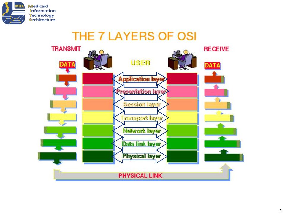
International Standards Organization (ISO) defined communications model, Open Systems Interconnection (OSI) reference model Levels HL7 corresponds to the conceptual definition of an application-to-application interface placed in the seventh layer of the OSI model. 7 6 5 4 3 2 1

6
MITA Technical Functions
International Standards Organization (ISO) defined communications model, Open Systems Interconnection (OSI) reference model Levels 7 MITA Business Process. MITA Technical Functions 6 5 4 3 2 1
 defined communications model, Open Systems Interconnection (OSI) reference model. Levels. 7. MITA Business Process. MITA Technical Functions")
7
NHIN Services Interface Standard Description Subject Discovery PIXv3
Service for locating patients based on demographic information Query for Documents XCA Locate health documents associated with a specific patient that conforms to a set of criteria Retrieve Documents Retrieve specific requested documents associated with a patient Query Audit Log IHE ATNA Log requests for patient health information and make this log available to patients. Authorization Framework SAML Articulate the justification for requesting patient medical information Consumer preference XACML Enable consumers to specify with whom they wish to share their electronic health information Messaging SOAP/WSDL/WS-addressing/ws-security Provide secure messaging services for all communication between nhin ENABLED HEALTH ORGANIZATIONS Authorize Case follow up Provide an ability to re-identify pseudonymized patient record when legally permitted for public health case investigation Health Information Event messaging WS-Base Notification Provides a publish/subscribe capability for ongoing feeds of data between NHIN enabled health organizations NHIE Service registry UDDI Registry that enables NHIN enabled health organizations to discover the existence and connection information for other NHIN enabled health organizations

8
MITA Basics

9
MITA Medicaid Enterprise
CDC Department of Homeland Security CMS Notifications and Alerts Notifications and Alerts MSIS Data; Dual Eligibility Other Agency License Board FEA FHA ONC Guidelines; Directives Interface Interface MITA Business Process #1 Standards of Interoperability; EHR Other Payer Interface RHIO Interface MITA Business Process #2 MITA Business Process #3 Interface Interface Use Standards; Develop New Ones Interface Interface Standards Organization Interface Provider SURS or Fraud Contractor Information Exchange Benefit Manager State Unemploy- ment Agency – MITA guidelines apply; FFP available – Entity is encouraged to follow MITA guidelines – May exchange information; may influence MITA or vice versa

10
Business Process Model v2.01
Operations Management Program Management Contractor Management Member Management Determine Eligibility Enroll Member Disenroll Member Manage Member Information Inquire Member Eligibility Perform Population & Member Outreach Manage Applicant & Member Communication Manage Member Grievance & Appeal 26 19 9 8 Authorize Referral Inquire Payment Status Draw and Report FFP Manage F-MAP Inquire Contractor Information Award Administrative or Health Services Contract Authorize Service Manage Drug Rebate Manage Rate Setting Manage FFP for Services Manage Contractor Information Close out Administrative or Health Services Contract Authorize Treatment Plan Manage Estate Recovery Manage FFP for MMIS Manage State Funds Manage Contractor Communication Manage Administrative or Health Services Contract Apply Attachment Prepare COB Formulate Budget Manage 1099s Perform Contractor Outreach Produce Administrative or Health Services RFP Apply Mass Adjustment Prepare EOB Develop Agency Goals & Objectives Maintain State Plan Support Contractor Grievance and Appeal Audit Claim-Encounter Manage Recoupment Develop & Maintain Program Policy Develop & Maintain Benefit Package Edit Claim-Encounter Manage Cost Settlement Maintain Benefits- Reference Information Perform Accounting Functions Manage TPL Recovery Prepare Medicare Premium Payment Designate Approved Services & Drug Formulary Monitor Performance & Business Activity Price Claim – Value Encounter Manage Payment Information Monitor Performance & Business Activity Manage Program Information Prepare Remittance Advice-Encounter Report Calculate Spend-Down Amount Dev. & Manage Perform. Measures & Reporting Prepare Provider EFT-check Prepare Capitation Premium Payment Prepare Premium EFT-check Prepare Member Premium Invoice Here is your vision test for the day! Please do not strain to read the content of each tiny box. Instead, let me walk you through the important things to recognize. The MITA BPM has 8 Business Areas. [read each BA title aloud] These likely sound familiar to you. Although states may have their own names for these areas, the functions within each are relatively easy to recognize and common to most Programs. Each one of the 8 Business Areas has defined Business Processes. These definitions include descriptions, triggers, process steps, results, dependencies, etc… Through the course of the SS-A, we will help your team identify the corresponding Business Area and Process within your organization, then gather the appropriate stakeholders to define where you align with the MITA definitions and where you may differ. There is no requirement to align completely today. Rather this documentation helps lay the foundation for understanding where your state can leverage MITA components and where you will have to implement additional development to accommodate state-specific requirements. Prepare Health Insurance Premium Payment Prepare Home & Community Based Services Payment Program Integrity Management Care Management Business Relationship Management Provider Management 2 4 4 7 Identify Candidate Case Manage Case Establish Case Manage Medicaid Population Health Establish Business Relationship Terminate Business Relationship Enroll Provider Manage Provider Communication Manage Case Manage Registry Manage Business Relationship Manage Business Relationship Comm. Disenroll Provider Manage Provider Grievance & Appeal Inquire Provider Information Perform Provider Outreach Manage Provider Information

11
Technical Functions Framework 2.0 Framework 2.0 Plus
Technology Standards Application Architecture Technical Services Technical Capability Matrix Business Services Solution Sets Technology Standards Application Architecture Technical Services Technical Functions Business Services Solution Sets Achieves consistency Business process equivalent to technical function BP -> ML -> BS -> SS TF -> ML -> TS -> SS Inconsistent use of the word “capabilities” in TA Not consistent with taxonomy of the business architecture BA -> BP -> ML -> BS -> SS TCM -> ML -> TS -> SS

12
Technical Functions Examples of technical functions are Authentication and Authorization. Interfaces to technical functions modeled as triggers and results. Technical function only exists to enable the business processes. Initially, technical functions will be defined using a template but like the business processes will ultimately be based on UML models. Technical function maturity level pairs (function + capability) will result in a technical service. The technical functions are being defined by the Private Sector Technology Group’s Technical Architecture Committee (TAC).
 will result in a technical service. The technical functions are being defined by the Private Sector Technology Group’s Technical Architecture Committee (TAC).")
13
Technical Maturity Levels Are Based on Industry Standards
Framework 2.0 Technical Services Technical Function Maturity Levels 5 4 3 2 1 Framework 2.0 Plus Maturity Levels Z ….. B A Technical Services Technical Function One to many maturity levels for each technical functions Maturity levels are specified by letter (A, B, C) Maturity levels only have meaning within the scope of that particular technical function Provides flexibility Artificially linked technology to MITA Business maturity Did not allow flexibility for industry standards Did not provide flexibility in designing technical services/solution sets
 Maturity levels only have meaning within the scope of that particular technical function. Provides flexibility. Artificially linked technology to MITA Business maturity. Did not allow flexibility for industry standards. Did not provide flexibility in designing technical services/solution sets.")
14
Benefits of New Maturity Level Approach
Technical maturity no longer maps technology to the five levels of business maturity. Instead each technical function is defined with its own independent maturity levels. The technical function may have one or many levels of maturity based on the industry standards for that particular technical function. This allows a technical service to be based on the industry derived capabilities/maturity levels. Solution sets for business services can make use of a heterogeneous mix of technical maturity levels based on the value that they bring to the business process.

15
Technical Services Update
There have been no structural changes to the concept of Technical Services. A service can be defined for each technical function—maturity level pair. The methodology used to define the technical service is the same as for business services, i.e., HL7. The HL7 Reference Information Model will be used in the development of the technical service interfaces whenever possible.

16
Application Architecture Updates
The application architecture captures technical infrastructure needs that can not be defined as a technical function/technical service. An example of this is an enterprise service bus. Each element of the application architecture will have technical maturity levels and technical solution sets. Application Architecture Technical Service Technical Service Business Service End User Technical Service Technical Service

17
Technical Solution Sets
The role of technical solution sets remains unchanged. There may be one or many technical solution sets for each technical function—maturity level or application element-maturity level pair. A solution set has the metadata describing a specific implementation approach.

18
Technical Maturity Levels
Framework 2.0 Framework 2.0 Plus Business Service Business Process Maturity Levels 5 4 3 2 1 Business Solution Set Technical Service Technical Function A Maturity Levels 5 4 3 2 1 Technical Solution Set Technical Function B Business Service Business Process Maturity Levels 5 4 3 2 1 Business Solution Set Maturity Levels D B A Technical Services Technical Function C Technical Solution Set

19
Relation to Business Service Solution Sets
Business services solution sets contain pointers to all technical function—maturity level pairs that are used by the particular implementation of the business service. Allows maximum flexibility for the implementer to use the mix of technology while maintaining a loose inventory of technology available for use.

20
Technical Assessment Framework 2.0 Sporadically mentioned
Process same as Business process self assessment Resulted in an assessment of the technical maturity in terms of the five levels of MITA Business Maturity Assessed technology for technology sake Framework 2.0 Plus Refocuses assessment process on business Process is now an inventory of the technical services and applications available Technical assessment is performed to determine what technical assets are currently available in a State’s infrastructure that can support future business needs Used in conjunction with Business service solution sets and the “to-be” business service assessment to determine technical needs to meet the business “to-be” configuration.

21
MITA Technical Services
Goal is to support semantic interoperability of the MITA business processes and technical functions Interface standardization begins at Maturity level 3 Provides enabling functionality to business services Examples Gateways/adapters CAQH Content X12 Communications CAQH connectivity NHIN EDI Authorization & Authentication Audit logging Encryption

22
Business Capability Maturity
MITA Business Process, Business Capability Matrix, and Business Services Definition Description of business logic Performance measures Business Logic Business Process Trigger Result Level 1 Capability Level 2 Level 3 Level 5 Level 4 Business Capability Maturity Once the MITA Business Processes have been identified the next step is to develop the MITA Business Service. As part of the development of the Business Process an entry in the business capability maturity matrix was developed for each process (For a more detail discussion of the MITA CMM see the MITA whitepaper.). For each business processes non-level 1 ( and optionally level 2) capability a single business service will be developed. This relationship is shown in the diagram. Level 2 Business Service Level 3 Level 4 Level 5
. For each business processes non-level 1 ( and optionally level 2) capability a single business service will be developed. This relationship is shown in the diagram. Level 2. Business. Service. Level 3. Level 4. Level 5.")
23
Purpose of a MITA Business Service
The MITA Business service is a logical implementation of a Medicaid Enterprise business process (e.g., Enroll Provider) The MITA business service supports Interoperability and plug-and-play States adapting and extending the service to meet their individual requirements A MITA business service is implementation neutral MITA business service A service is the basic element in a Service Oriented Architecture (SOA). A goal of an SOA is to provide services that have a concrete meaning on the business level. A service is a software element that provides a complete business process or function. Service - an resource that provides a capability of performing tasks that form a coherent functionality Business Service - corresponds to the logical implementation of an Business Process in a web service. The business service contains a service maturity level description and a Business Service Definition Package The MITA Business Service allows two things- “Plug n Play” - An individual service can be replaced with a new implementation without impacting the rest of the enterprise. (Replace a service that is currently a wrapped COBOL application with a COTS product or J2EE C++ program., without changing any of the external interfaces.) “Interoperability” – The ability to change an external user of a service without changing the service. This could delete, add or modify external services, or clients ( A new service ( could be an application or other client) is added to the enterprise that takes as input the output from an existing service)
 The MITA business service supports. Interoperability and plug-and-play. States adapting and extending the service to meet their individual requirements. A MITA business service is implementation neutral. MITA business service. A service is the basic element in a Service Oriented Architecture (SOA). A goal of an SOA is to provide services that have a concrete meaning on the business level. A service is a software element that provides a complete business process or function. Service - an resource that provides a capability of performing tasks that form a coherent functionality. Business Service - corresponds to the logical implementation of an Business Process in a web service. The business service contains a service maturity level description and a Business Service Definition Package. The MITA Business Service allows two things- Plug n Play - An individual service can be replaced with a new implementation without impacting the rest of the enterprise. (Replace a service that is currently a wrapped COBOL application with a COTS product or J2EE C++ program., without changing any of the external interfaces.) Interoperability – The ability to change an external user of a service without changing the service. This could delete, add or modify external services, or clients ( A new service ( could be an application or other client) is added to the enterprise that takes as input the output from an existing service)")
24
Black Box Concept of a Service
Custom Code Service COTS Service Legacy Application Service look identical on the outside same input same output same behavior Inside (“under the hood”) they can be very different. As shown here a service can be all custom code, or a COTS product, or wrapped legacy code, or a combination of the above, or a composite of other services. Service Custom Code COTS Custom Code Service Service Service Service
 they can be very different. As shown here a service can be all custom code, or a COTS product, or wrapped legacy code, or a combination of the above, or a composite of other services. Service. Custom. Code. COTS. Custom. Code. Service. Service. Service. Service.")
25
Formally defined interface Behavior characteristics Business logic
Parts of a MITA Service Service name Formally defined interface Behavior characteristics Business logic Service Contract (Processing pattern, etc.) Business Service Definition Package (BSDP) In the MITA framework a business service must have the following associated data Service name is the name that the service is invoked by Formally defined interface – the interface is defined by using the Web service definition language (WSDL) Behavior characteristics business logic – describes what goes on under the hood of the business service service contract – describes the expected behavior of the interface ( eg is the interface a real time or online interface) The BSDP is a MITA defined set of metadata describing the service
 Business Service Definition Package (BSDP) In the MITA framework a business service must have the following associated data. Service name is the name that the service is invoked by. Formally defined interface – the interface is defined by using the Web service definition language (WSDL) Behavior characteristics. business logic – describes what goes on under the hood of the business service. service contract – describes the expected behavior of the interface ( eg is the interface a real time or online interface) The BSDP is a MITA defined set of metadata describing the service.")
26
Services are loosely coupled
MITA Service Flow Services are loosely coupled NO predefined predecessor or successor services to an individual service Services configured through use of a service contract and an orchestration language Changes to the flow of services through changes to this orchestration; NOT by changes to the service Interfaces between the services must be compatible The business service’s objective is to provide an independent version of a business process that can woven together with other services to form composite business processes. Service contract is defined by the web service definition language and service patterns. Orchestration is done using Business Process Execution Language

27
Interoperability - Replacement
Service A Service B Service C Starting Configuration Service A Service B1 Service C Final Configuration Starting configuration is three services that have been orchestrated serially to form a composite business service. The change is that the middle service is replaced with a new service. Examples of this are: replacement of a legacy service with COTS Replacing an existing service with a new services cont6aining new Medicaid regulations As long as the interface does not change for the service the preceding and succeeding services do not have to be changed to successfully run with the new service e.g., replacement of legacy service with COTS

28
Interoperability – Addition
Service A Service B Service C Starting Configuration Service A Service B Service C Starting configuration is three services that have been orchestrated serially to form a composite business service. The change is that a new service. Has been added to the front end Examples of this are: HIPAA translator Web enabled The only change required is to orchestrate Service D into the composite service. As long as the interface does not change for the service B none of the existing services need to be changed to successfully run with the new service Final Configuration Service D e.g., HIPAA translator

29
Interoperability – New
Service A Service B Service C Starting Configuration Service A Service B Service C Service E Starting configuration is three services that have been orchestrated serially to form a composite business service. The change is that a new service. Has been added to the back end Examples of this are: New utilization review The only change required is to orchestrate Service E into the composite service. As long as the interface does not change for the service C none of the existing services need to be changed to successfully run with the new service Final Configuration e.g., new utilization review process

30
Interoperability – New Business Process
Service A Service B Service C Starting Configuration Service A Service B3 Service C Starting configuration is three services that have been orchestrated serially to form a composite business service. The change is that service B is replaced with the new service B3 which generates an additional response. The new response is used by a brand new service, Service F. The only changes required are to orchestrate the new response from Service B3 and Service F into the composite service. As long as the interface does not change the existing interfaces for the service B none of the existing services need to be changed to successfully run with the new services Final Configuration Service F e.g. , utilization review service with new potential fraud report e.g., automated fraud detection processing

31
Business Process and Business Service Relationship
Definition Description of business logic Performance measures Business Process Business Logic Trigger Result What does the service do and what is needed to engage the service Business capability Business Service WSDL defined Service Contract WSDL defined Business Logic Data The business process and capability are used to define the services business logic and service contract. A services interface is derived from the business processes trigger and responses and is described using the Web Definition Language (WSDL) Example Eligibility Inquiry Response HIPAA 271 XML schema Example Eligibility Inquiry HIPAA 270 XML schema Performed by legacy subsystem, new code or services, COTS or combination Shared between or with other services
 Example. Eligibility Inquiry Response. HIPAA 271 XML schema. Example. Eligibility Inquiry. HIPAA 270 XML schema. Performed by legacy subsystem, new code or services, COTS or combination. Shared between or with other services.")
32
MITA Service Definition Methods
Interfaces are defined in Web Service Definition Language (WSDL) Messages are defined in XML schemas Business Logic – currently free form text, will become business rules in the future Business Service Management (orchestration) is defined in Web Service – Business Process Execution Language (WS-BPEL) Data is defined in MITA logical data model
 Messages are defined in XML schemas. Business Logic – currently free form text, will become business rules in the future. Business Service Management (orchestration) is defined in Web Service – Business Process Execution Language (WS-BPEL) Data is defined in MITA logical data model.")
33
State Personalization of Services
Change Message Structure - Schema change Change data being used – Change data set name (e.g., instead of mapping to “state-A-MVA” map to “state-B-MVA) Replace capability – Replace service with state unique service preserving input and output Re-Orchestrate business services – Add new services to flow Change business rules – Replace the set of business rules used by a service with a new set of business rules An example of when a schema change could be used is if the standard schema show certain entities as being optional and a state wants its implementation to have the entities as mandatory. That data set being used by either replacing the dataset itself or by changing the name of the data set to be used. Replacing a services was already discussed in the previous slides. Re-orchestration can be used to recombine existing services or to add new services
 Replace capability – Replace service with state unique service preserving input and output. Re-Orchestrate business services – Add new services to flow. Change business rules – Replace the set of business rules used by a service with a new set of business rules. An example of when a schema change could be used is if the standard schema show certain entities as being optional and a state wants its implementation to have the entities as mandatory. That data set being used by either replacing the dataset itself or by changing the name of the data set to be used. Replacing a services was already discussed in the previous slides. Re-orchestration can be used to recombine existing services or to add new services.")
34
Service Interface Specification Development Process
Standard Analysis Applicable Standard Report MITA Business Process Specification (template & BCM) Model Business Process MITA Governance Boards (Adoption packages) Develop BS Interface Specification adoption recommendation (WSDL, XML Schema and models) (Adoption packages) Coordinate with TAC and identify Technical Service gaps TAC
 Model. Business. Process. MITA. Governance. Boards. (Adoption packages) Develop BS Interface. Specification adoption. recommendation. (WSDL, XML Schema and models) (Adoption packages) Coordinate. with TAC and. identify Technical. Service gaps. TAC.")
35
Putting it all together

36
Service Orchestration
Business Service Invocation Business Service - B Technical Service- 3 True Technical Service - 1 Technical Service - 2 Business Service - A Business Service- C False Service orchestration are the sequencing rules used to provide a business service. Currently for MITA this service orchestration is not dynamic but is configured prior to execution of the business service. Shown is the figure is a generic example of a service orchestration. Business services shown are one of the ~100 MITA Business Services (i.e. enroll member, enroll provider, calculate spend-down, etc.) MITA technical services provide technical functions such as security, privacy, logging, forms management, etc Business Service- D
 MITA technical services provide technical functions such as security, privacy, logging, forms management, etc. Business. Service- D.")
37
Service Contract Interaction Specification Service “XYZ” Service
Request Interface Request Interface Response Service contracts document the rules and procedures used to activate a service. These service contracts are used by the Enterprise service bus and service management engine to activate a service and to route responses from the service.

38
Sample Service #2 – Member Eligibility and Enrollment
Step 1: Member Invokes “Determine Eligibility” Service Step 6: Provider Receives “Determine Eligibility” Response Step 11: Member completes enrollment form Sample Service #2 – Member Eligibility and Enrollment Enrollment Info Request Step 10: Send request for more info Enrollment Response Access Channel Determine Eligibility Request Enrollment Info Response Member Service Portal Eligibility Response Step 9: Route request for more information to Service Portal MITA Enrollment Info Request Security & Privacy Services Eligibility Response MITA Determine Logging Services MITA Enrollment Response Data Format Services MITA Determine Eligibility Request MITA Enrollment Info Response Step 5: Receive/ Route/ Manage Step 2: Receive/ Route/ Manage Enterprise Service Bus Determine Eligibility Service Contract Service Management Engine Enroll Member Service Contract Step 7: Service contract – “activate” enroll member service This slide shows the orchestration of a two MITA Business Services. The Determine Eligibility and Enroll Member services are executed in this example, the scenario demonstrates a potential beneficiary checking if they are eligible and then doing a self-enrollment. Even though this scenario shows a potential member initiating the process it could be also be a MEDICAID administrator. Step 1 – A potential member makes a request via the MITA access channel. This request could be done by using a web client, PDA or Kiosk. The Access Channel and Provider Service Portal will call MITA technical services to perform the following activities Data Format Services – support device specific protocols, wrap payload data with MITA envelope, and perform high level data validation. Security & Privacy Services – authenticate user, single logon, validate user is authorized to perform this function, validate user is authorized to use data (privacy) Logging Services – captures all input/output data to a log. Note: some of the services may be invoked from the ESB and not the service portal. These details are still being worked and will be included in Framework 2 Step 2 – The Enterprise Service Bus (ESB) an Service Management Engine (SME) route the MITA message to the appropriate MITA business service. The service contract is used to determine how this service is invoked. It should be noted that the service may not be on the same platform as the ESB receiving the request. In this case the ESB/SME will determine where the service is located and routing the message to the appropriate ESB. Step 3 – The Determine Eligibility Service receives the MITA determine eligibility request and executes the business logic associated with the request. Step 4 – This scenario demonstrates a successful execution of the business logic resulting in a message sent back indicating potential beneficiary is eligibility. The message generated is a MITA formatted message ( i.e. MITA envelope and payload) Step 5 – ESB/SME determines what to do after receiving response message ( was message expected, who should receive the message, should other business services be invoked). In this example the Determine Eligibility Response message is routed to the Service portal. The SME also determines that the enroll member service should also be activated based on the successful ( potential member is eligible) determine eligibility. Steps 6 and 7 are both initiated Step 6 – The service portal/access channel log the response, validate security and privacy rules, and translate the data into the specific format required by the hardware used by the requestor. The potential member then receives the response that they are eligible. Step 7 – ESB/SME activate enroll member service with enroll member request Step 8 – Enroll Member Service executes business logic and determines that additional information is needed to perform the enrollment A MITA message is generated requesting the additional information. Step 9 – ESB/SME routes message to service portal Step 10 – The service portal/access channel log the response, validate security and privacy rules, and translate the data into the specific format required by the hardware used by the potential member. The potential member then receives the request for additional information for enrollment. This scenario shows the member is deciding to enroll, but in reality member may decide not to self enrollment at this time Step 11 – Member receives request for enrollment information and completes form Step 12 – The service portal/access channel log the response, validate security and privacy rules, and translate the data into the MITA format . Step 13 ESB/SME route Enrollment information response to enroll member service Step 14 Enroll Member service executes business logic to process enrollment information response It should be noted that the figure does not show that the business service also updates other shared data ( i.e. plan registries) stores Step 15 Enroll Member service generates and sends MITA message for successful enrollment. Step 16 ESB/SME routes message to service portal Step 17 The service portal/access channel log the response, validate security and privacy rules, and translate the data into the specific format required by the hardware used by the requestor. The member then receives the response that they are enrolled. Step 3: Execute Determine Eligibility Business Process MITA Determine Eligibility Request MITA Determine Eligibility Response Member Request MITA Enroll MITA Enrollment Info Request MITA Enrollment Info Response MITA Enrollment Response Step 8: Request Information for enrollment Determine Eligibility Service Enroll Member Service Step 4: Return Response
 Logging Services – captures all input/output data to a log. Note: some of the services may be invoked from the ESB and not the service portal. These details are still being worked and will be included in Framework 2. Step 2 – The Enterprise Service Bus (ESB) an Service Management Engine (SME) route the MITA message to the appropriate MITA business service. The service contract is used to determine how this service is invoked. It should be noted that the service may not be on the same platform as the ESB receiving the request. In this case the ESB/SME will determine where the service is located and routing the message to the appropriate ESB. Step 3 – The Determine Eligibility Service receives the MITA determine eligibility request and executes the business logic associated with the request. Step 4 – This scenario demonstrates a successful execution of the business logic resulting in a message sent back indicating potential beneficiary is eligibility. The message generated is a MITA formatted message ( i.e. MITA envelope and payload) Step 5 – ESB/SME determines what to do after receiving response message ( was message expected, who should receive the message, should other business services be invoked). In this example the Determine Eligibility Response message is routed to the Service portal. The SME also determines that the enroll member service should also be activated based on the successful ( potential member is eligible) determine eligibility. Steps 6 and 7 are both initiated. Step 6 – The service portal/access channel log the response, validate security and privacy rules, and translate the data into the specific format required by the hardware used by the requestor. The potential member then receives the response that they are eligible. Step 7 – ESB/SME activate enroll member service with enroll member request. Step 8 – Enroll Member Service executes business logic and determines that additional information is needed to perform the enrollment A MITA message is generated requesting the additional information. Step 9 – ESB/SME routes message to service portal. Step 10 – The service portal/access channel log the response, validate security and privacy rules, and translate the data into the specific format required by the hardware used by the potential member. The potential member then receives the request for additional information for enrollment. This scenario shows the member is deciding to enroll, but in reality member may decide not to self enrollment at this time. Step 11 – Member receives request for enrollment information and completes form. Step 12 – The service portal/access channel log the response, validate security and privacy rules, and translate the data into the MITA format . Step 13 ESB/SME route Enrollment information response to enroll member service. Step 14 Enroll Member service executes business logic to process enrollment information response. It should be noted that the figure does not show that the business service also updates other shared data ( i.e. plan registries) stores. Step 15 Enroll Member service generates and sends MITA message for successful enrollment. Step 16 ESB/SME routes message to service portal. Step 17 The service portal/access channel log the response, validate security and privacy rules, and translate the data into the specific format required by the hardware used by the requestor. The member then receives the response that they are enrolled. Step 3: Execute Determine Eligibility Business Process. MITA Determine. Eligibility. Request. MITA Determine. Eligibility. Response. Member Request. MITA Enroll. MITA Enrollment. Info Request. MITA Enrollment. Info Response. MITA Enrollment. Response. Step 8: Request Information for enrollment. Determine Eligibility. Service. Enroll Member. Service. Step 4: Return Response.")
39
Sample Service #1 – Provider Enrollment
Step 1: Provider Invokes “Enroll Provider” Service Step 6: Provider Receives “Enroll Provider” Response Sample Service #1 – Provider Enrollment Access Channel Enrollment Request Provider Service Portal Enrollment Response MITA Enrollment Request MITA Enrollment Response Security & Privacy Services Logging Services Data Format Services Step 2: Receive/ Route/ Manage Step 5: Receive/ Route/ Manage Enterprise Service Bus Provider Enrollment Service Contract Service Management Engine This slide shows the orchestration of a single MITA Business Service. The Enroll Provider service is executed in this example, the scenario demonstrates a provider doing a self-enrollment. Step 1 – A provider makes a request via the MITA access channel. This request could be done by using a web client, PDA or Kiosk. The Access Channel and Provider Service Portal will call MITA technical services to perform the following activities Data Format Services – support device specific protocols, wrap payload data with MITA envelope, and perform high level data validation. Security & Privacy Services – authenticate user, single logon, validate user is authorized to perform this function, validate user is authorized to use data (privacy) Logging Services – captures all input/output data to a log. Note: some of the services may be invoked from the ESB and not the service portal. These details are still being worked and will be included in Framework 2 Step 2 – The Enterprise Service Bus (ESB) an Service Management Engine (SME) route the MITA message to the appropriate MITA business service. The service contract is used to determine how this service is invoked. It should be noted that the service may not be on the same platform as the ESB receiving the request. In this case the ESB/SME will determine where the service is located and routing the message to the appropriate ESB. Step 3 – The Enroll Provider Service receives the MITA enroll provider request and executes the business logic associated with the request. Step 4 – This scenario demonstrates a successful execution of the business logic resulting in a message sent back indicating successful enrollment. The message generated is a MITA formatted message ( i.e. MITA envelope and payload) Step 5 – ESB/SME determines what to do after receiving response message ( was message expected, who should receive the message, should other business services be invoked). In this example the Enrollment Response message is routed to the Service portal. Step 6 – The service portal/access channel log the response, validate security and privacy rules, and translate the data into the specific format required by the hardware used by the requestor. The provider then receives the enrollment response MITA Enrollment Request MITA Enrollment Response Step 3: Execute Provider Enrollment Business Process Step 4: Return Response Enroll Provider Service
 Logging Services – captures all input/output data to a log. Note: some of the services may be invoked from the ESB and not the service portal. These details are still being worked and will be included in Framework 2. Step 2 – The Enterprise Service Bus (ESB) an Service Management Engine (SME) route the MITA message to the appropriate MITA business service. The service contract is used to determine how this service is invoked. It should be noted that the service may not be on the same platform as the ESB receiving the request. In this case the ESB/SME will determine where the service is located and routing the message to the appropriate ESB. Step 3 – The Enroll Provider Service receives the MITA enroll provider request and executes the business logic associated with the request. Step 4 – This scenario demonstrates a successful execution of the business logic resulting in a message sent back indicating successful enrollment. The message generated is a MITA formatted message ( i.e. MITA envelope and payload) Step 5 – ESB/SME determines what to do after receiving response message ( was message expected, who should receive the message, should other business services be invoked). In this example the Enrollment Response message is routed to the Service portal. Step 6 – The service portal/access channel log the response, validate security and privacy rules, and translate the data into the specific format required by the hardware used by the requestor. The provider then receives the enrollment response. MITA Enrollment. Request. MITA Enrollment. Response. Step 3: Execute Provider Enrollment Business Process. Step 4: Return Response. Enroll. Provider. Service.")
40
MITA Medicaid Enterprise
CDC Department of Homeland Security CMS Notifications and Alerts Notifications and Alerts MSIS Data; Dual Eligibility Other Agency License Board FEA FHA ONC Guidelines; Directives Interface Interface MITA Business Process #1 Standards of Interoperability; EHR Other Payer Interface RHIO Interface MITA Business Process #2 MITA Business Process #3 Interface Interface Use Standards; Develop New Ones Interface Interface Standards Organization Interface Provider SURS or Fraud Contractor Information Exchange Benefit Manager State Unemploy- ment Agency – MITA guidelines apply; FFP available – Entity is encouraged to follow MITA guidelines – May exchange information; may influence MITA or vice versa Business Service Technical Service Connection

41
The TAC’s 5010 Gateway Project
GUI Phase 1 Inquire Member Eligibility 1 GUI Phase 2 IME TS-B1 TS-C1 GUI Phase 3 IME TS-A TS-B1 TS-C1 TS-D Legend Business Service Technical Service GUI Potential Post Phase 3 Other Business Services TS TS-B TS-C TS TS TS

42
IME Test Suite Dash- Board Inquire Member Eligibility BS CAQH Core In
Connectivity TS X12/MITA XML adapter TS Dash- Board Inquire Member Eligibility BS MITA XML/X12 adapter TS CAQH Core Out Connectivity TS

43
Technical Implementer
The Big Picture MITA Users STAG MITA Review Boards ARB Technical Implementer New Bus Proc BARB TARB IARB NMEH TAC Roles and responsibilities MITA Review Boards Adoptions of MITA specifications Evaluation of recommendations Harmonization of collateral architecture impacts Notification Changes to MITA standards to MITA user community NMEH Business process recommendations Business process capability level recommendations HL7-MITA Workgroup Business Process Information Model recommendations Business Service WSDL recommendations Harmonization recommendation between MITA and HL7 (vocabulary, models, data types, code sets) Interface between MITA and HL7 TAC Technical function recommendations Technical Function capability level recommendations Technical Function Information Model recommendations Technical Service WSDL recommendations Harmonization recommendation between MITA and Technical DSMO Interface between MITA and technical industry Other DSMOs State Business SMEs HL7-MITA Project Independent Information Spec. HL7 HL7Healtth Data Community
 Interface between MITA and HL7. TAC. Technical function recommendations. Technical Function capability level recommendations. Technical Function Information Model recommendations. Technical Service WSDL recommendations. Harmonization recommendation between MITA and Technical DSMO. Interface between MITA and technical industry. Other DSMOs. State Business. SMEs. HL7-MITA. Project. Independent. Information Spec. HL7. HL7Healtth Data. Community.")
44
MITA Architecture Governance Structure
Review Board MITA Business Architecture Information Architecture Technical Architecture Business Process Business Capability S-SA process Conformance Criteria Data Models Vocabulary Mapping to Standards Data Management Strategy Service definitions Infrastructure definitions Technical processes Technical capabilities MITA Standards Framework updates

45
MITA Architecture Governance Artifacts
Review Board MITA Business Architecture Information Architecture Technical Architecture Business Process Templates Activity diagrams Business Capability Business Information Vocabulary and glossary Conformance Criteria Data Models and associated views WSDL and associated XSD Information Vocabulary and glossary Mapping to Standards Service definitions Technical Functions Technical Information Vocabulary and glossary Tec Function capabilities Infrastructure definitions MITA Standards Framework updates

Similar presentations

 Ltd>")


 Process Flow Diagram (Move-In) Customer Supplier Customer authorizes Enrollment (11.3.2.1)>")


