Download presentation
Presentation is loading. Please wait.

1
Group 5 Tony Joseph Sergio Martinez Daniel Rultz Reginald Brandon Haas Emmanuel Sacristan Keith Bellville

2
To understand the organization of the CPU, we must learn those requirement which are Fetch instructions Interpret instructions Fetch data Process data Write data Organization of the CPU

3
Fetch instructions: the CPU reads an instruction from the memory Interpret instruction: the instruction is decode to determine what action is required Fetch data: the execution of an instruction may require reading data from memory or an I/o module Process data: the execution of an intruction may require to perform arithmetic or logic operation Instruction Definition

4
Write data: the results of an executive may require writing data to memory or an I/O module. The CPU is connected to the rest of the system by the system bus. The major components of the CPU are the arithmetic and logic unit (ALU) and control unit (CU). Definitions Cont.
 and control unit (CU). Definitions Cont..")
5
The ALU does the actual computation or processing of data. The CU controls the movement of the data and instruction into and out of the CPU and controls the operation of the ALU. It has a minimal internal memory called register ALU and CU

8
Computer employs memory hierarchy, at higher levels of hierarchy, memory is faster, smaller and more expensive. Within the processor, there is a set of registers that function as a level of memory above main memory and cache in the hierarchy level. Registers in the Processor Registers in the Processor User-visible User-visible Control and Status Control and Status

9
May be referenced by machine language programmer: General purpose Data Address Condition codes User-Visible Registers

10
Data (hold data only) Addressing (general purpose or addressing mode) Segment pointers Index Stack pointer General Purpose True general purpose (can contain the operand for any opcode) Restricted (dedicated for floating and stack operations) Sometimes used for addressing and data.
 Addressing (general purpose or addressing mode) Segment pointers Index Stack pointer General Purpose True general purpose (can contain the operand for any opcode) Restricted (dedicated for floating and stack operations) Sometimes used for addressing and data.")
11
Make them general purposeMake them specialized Increase flexibility and programmer options Increase instruction size & complexity Smaller (faster) instructions Less flexibility
 instructions Less flexibility")
12
Condition Codes An arithmetic operation may produce a positive, negative, zero, or overflow result. Those results are stored into one or more registers, usually forming part of control registers. They can be read but not altered by the programmer. The condition code may be tested as part of a conditional branch operation. Many processors do not use condition codes, but they use conditional branch instructions to make comparison without using condition codes.

13
Condition Codes Advantages and Disadvantages: Advantages: Reduce the number of compare and test instructions needed. Conditional instructions are simplified to composite instructions. Facilitate multi-way branches. Disadvantages: Add complexity to hardware and software. Irregular, they are not typically part of data path, so they require extra wire connections. Must add non-condition code instructions. In a pipeline implementation, they require special synchronization to avoid conflicts.

14
User-Visible Registers In some machines, a subroutine call will result in the automatic saving of all user-visible registers, to be restored on return. This allows each subroutine to use this registers independently. On other machines it is a task to be performed by the programmer.

15
1.- program counter 2.- instruction register 3.- memory address register 4.- memory buffer register

16
1.- Sign : contains the sign bit of the result 2.- Zero: set when the result is zero 3.- Carry: set if an operation resulted in a carry into or borrow out of high-order bit 4.-Equal: set if a logical compare result is equality 5.- Overflow: used to indicate arithmetic overflow 6.- Interrupt : used to enable or disable interrupts 7.- Supervisor : indicates whether the cpu is executing in supervisor or user mode

17
PCI Standard Registers VID - Vendor Identification Register DID - Device Identification Register RID - Revision Identification Register CCR - Class Code Register HDR - Header Type Register SID/SVID - Subsystem Identity/Subsystem Vendor Identification Register PCICMD - Command Register PCISTS - PCI Status Register SAD - System Address Decoder Registers SAD_PAM0123 SAD_PAM456 SAD_HEN SAD_SMRAM SAD_PCIEXBAR SAD_DRAM_RULE_0, SAD_DRAM_RULE_1, SAD_DRAM_RULE_2, SAD_DRAM_RULE_3 SAD_DRAM_RULE_4, SAD_DRAM_RULE_5 SAD_DRAM_RULE_6, SAD_DRAM_RULE_7 2.6.7 SAD_INTERLEAVE_LIST_0, SAD_INTERLEAVE_LIST_1 SAD_INTERLEAVE_LIST_2, SAD_INTERLEAVE_LIST_3 SAD_INTERLEAVE_LIST_4, SAD_INTERLEAVE_LIST_5 SAD_INTERLEAVE_LIST_6, SAD_INTERLEAVE_LIST_7

18
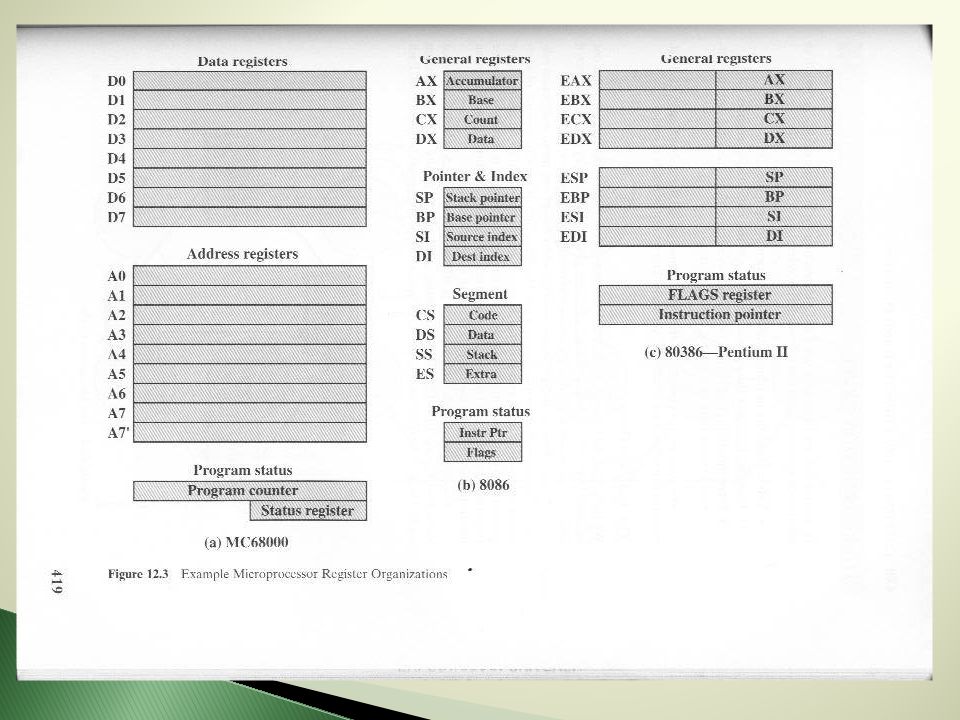
MC 68000 32 - bit register into eight data registers and nine address registers Intel 8086 16 bit data register, and four pointer and index register

20
To recap, basic instruction cycle contains: ◦ Fetch: Read the next instruction from memory into the processor. ◦ Execute: Interpret the opcode and perform the indicated operation. ◦ Interrupt: If interrupts are enabled and an interrupt has occurred, save the current process state and service the interrupt.

21
Execution requires memory access to one or more operands. Indirect addressing requires additional memory access. This can be thought of as an additional instruction stage.

22
Most activity consists of alternating between fetch and execute. Fetch opcode Check addressing Execute Check for Interrupt ◦ Service ◦ No interrupt Fetch next opcode

24
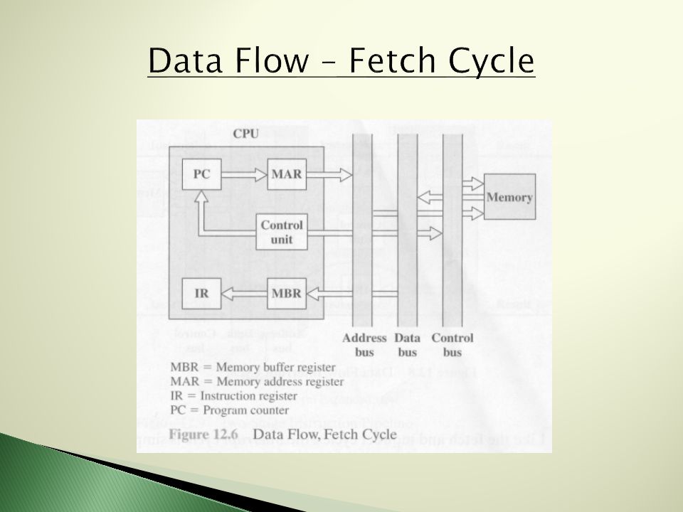
Event sequencing depends on design of processing unit. Assume processor uses: ◦ Memory Address Register (MAR) ◦ Memory Buffer Register (MBR) ◦ Program Counter (PC) ◦ Instruction Register (IR)
 ◦ Memory Buffer Register (MBR) ◦ Program Counter (PC) ◦ Instruction Register (IR).")
25
An instruction is fetched from memory PC Contains address of next instruction This address is moved to MAR and placed on address bus Control Unit requests memory read and result is placed on data bus to be placed into MBR and then to the IR. PC is incremented for the next fetch

27
Fetch cycle ends Control Unit examines IR for indirect addressing Rightmost N bits of the MBR moved to MAR CU requests memory read to get the address of operand into MBR

29
Contents of PC must be saved ◦ Moved to MBR to be written ◦ Special memory location for this purpose is loaded into MAR from the CU PC is loaded with address of interrupt routine Next instruction cycle begins with fetch

31
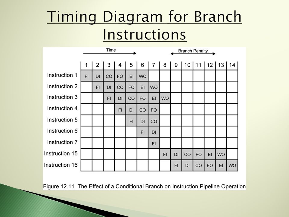
o Fetch Instruction ( FI ) o Decode Instruction ( DI ) o Calculate Operands ( CO ) o Fetch Operands ( FO ) o Execute Instruction ( EI ) o Write Operand ( WO ) Stages of Instruction Processing
 o Decode Instruction ( DI ) o Calculate Operands ( CO ) o Fetch Operands ( FO ) o Execute Instruction ( EI ) o Write Operand ( WO ) Stages of Instruction Processing")
32
Without pipelining, registers become idle between stages With pipelining registers can be used between stages by other instruction sets Very similar to an assembly line Various stages allows for multiple instructions sets to occur simultaneously Ideally the instruction sets go through all stages The more stages the better the pipeline

35
A pipeline hazard occurs when some portion of the pipeline must stall because conditions do not permit continued execution. The different hazards are: ◦ Resource Hazard ◦ Data Hazard ◦ Control Hazard

36
When two or more instructions require the same resource in a pipeline This causes execution to be done in serial as opposed to parallel This is sometimes referred to as a Structural Hazard Another example when two stages require access to the ALU

38
Read after write ( RAW ) : An instruction modifies a register or memory location before another instruction reads from said location. Hazard occurs if read takes place before write. Write after read ( WAR ) : Instruction reads a register or memory location before another instruction writes to location. Hazard occurs if write completes before the read. Write after write ( WAW ) : Two instructions write to the same location. Hazard occurs if write order occurs in reverse.
 : Instruction reads a register or memory location before another instruction writes to location. Hazard occurs if write completes before the read. Write after write ( WAW ) : Two instructions write to the same location. Hazard occurs if write order occurs in reverse..")
39
Known as a Branch Hazard Occurs when pipeline makes wrong decision on a branch prediction which brings in a instruction set that needs to then be discarded.

40
A major problem in designing a pipeline is dealing with conditional branch instructions. Impossible to determine if a branch will be taken until execution. There are several approaches to the problem of conditional branches.

41
Methods for dealing with branches ◦ Multiple Streams ◦ Pre-fetch the branch target ◦ Loop buffer ◦ Branch prediction ◦ Delayed branch

42
Simple pipelines suffer a penalty if they choose the wrong instruction for a branch. Solution, replicate initial pipeline portions. Fetch both instructions. Two problems with this approach. ◦ Register access delay. ◦ Each branch requires a stream.

43
Identify the conditional branch, prefetch the target. Prefetch the instruction after the target. Save the target. Target and instruction already fetched if branch is taken. Method is a gamble.

44
A small, high speed memory. Contains the most recently fetched instructions. Procedure if a branch is taken ◦ Check the loop buffer for the target ◦ Fetch instruction from loop buffer.

45
Loop buffer benefits ◦ Instructions in sequence will be available without the usual memory access time. ◦ Targets a few address locations ahead will be preloaded ◦ With a large enough buffer an entire loop’s worth of instructions need only be fetched once.

46
Common techniques for predicting. ◦ Predict never taken ◦ Predict always taken ◦ Predict by opcode ◦ Taken/not taken switch ◦ Branch history table

47
Predict never taken. ◦ Assume the branch is never taken ◦ Fetch instructions as if there were no branch Predict always taken. ◦ Assume the branch is always taken ◦ Fetch the instructions from the branch target Predict by opcode. ◦ Decide if a branch is taken by the branch opcode.

48
Taken/not taken switch. ◦ Record the history of branch instructions ◦ More than one bit is preferred ◦ Use the history as a guide for the next encounter ◦ A drawback, the target cannot be fetched until the target address is decoded.

50
Branch history table. ◦ A small cache of memory ◦ Helps solve the problem of taken/not taken switch ◦ Usually three elements in the table Address of the branch instruction A number of history bits Information about the target

51
Possible to improve the pipeline through rearranging instructions. Arrangements are made so that branches occur later in a program Further examined in chapter 13

52
1) What are the two major components of a CPU? 2) How are the user-visible registers classified? 3) What are the four registers needed in order for the control and status register to work? 4) All CPU designs include a register or set of registers often known as? 5) What register does the control unit examine to determine addressing mode? 6) Why do the PC contents need to be stored in memory in the event of an interrupt.
 What are the four registers needed in order for the control and status register to work. 4) All CPU designs include a register or set of registers often known as. 5) What register does the control unit examine to determine addressing mode. 6) Why do the PC contents need to be stored in memory in the event of an interrupt..")
53
7) What are the hazards in pipelining? 8) Does pipelining increase clock speed? 9) What is the difference between Predict Never Taken and Predict Always Taken? 10) What is one of the two problems with multiple streams?
 What is the difference between Predict Never Taken and Predict Always Taken. 10) What is one of the two problems with multiple streams .")
54
1) ALU and Control Unit 2) General purpose, Data, Address, Condition Code 3) The IR, PC, MAR, MBR 4) PSW 5) IR 6) Contents must be saved so the processor can resume normal activity after the interrupt.
 ALU and Control Unit 2) General purpose, Data, Address, Condition Code 3) The IR, PC, MAR, MBR 4) PSW 5) IR 6) Contents must be saved so the processor can resume normal activity after the interrupt.")
55
7) Control, data, and resource hazards 8) No, it increases the amount of instructions able to be completed in a given cycle. 9) PNT assumes the branch is never taken, PAT assumes the branch target will always be taken. 10) Multiple streams will encounter delays for access to a needed register or each stream can encounter a branch of its own.
 PNT assumes the branch is never taken, PAT assumes the branch target will always be taken. 10) Multiple streams will encounter delays for access to a needed register or each stream can encounter a branch of its own..")
56
Processors and datapath http://www.cise.ufl.edu/~mssz/CompOrg/CDA- proc.html http://www.cise.ufl.edu/~mssz/CompOrg/CDA- proc.html Pipelining overview http://arstechnica.com/old/content/2004/09/pipel ining-1.ars/1 http://arstechnica.com/old/content/2004/09/pipel ining-1.ars/1 Intel core i7 data sheet http://download.intel.com/design/processor/datas hts/320835.pdf http://download.intel.com/design/processor/datas hts/320835.pdf

Similar presentations