Download presentation
Presentation is loading. Please wait.

1
Status of the advanced LIGO laser O. Puncken, L. Winkelmann, C. Veltkamp, B. Schulz, S. Wagner, P. Weßels, M. Frede, D. Kracht

2
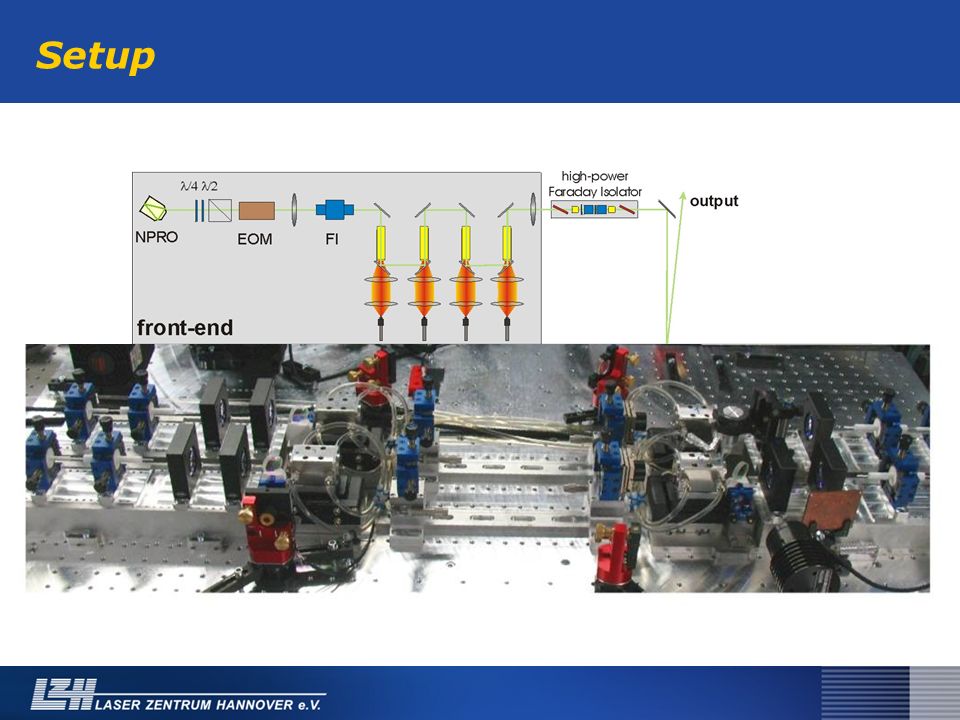
Content Setup Status in October 2007 Current status Characterization work –Crystals –Mirrors –Diodes System improvement / outlook –Crystal cooling

3
Advanced LIGO PSL: high power laser

4
Setup

6
Adv. LIGO electronics

7
Start-up behavior Complete system started and locked after 3 min ! status 10/07

8
Beam quality Output power: 180.5 W 91.5% (~165 W) in TEM 00 status 10/07
 in TEM 00 status 10/07")
9
53h test run Relock events status 10/07

10
Current status ≈ 174 W at 4 x 185 W pump power 91 % in TEM 00 DC noise ≈ 5% (not changed) Typical relock time < 50 ms (not changed) Startup: complete system started after 3 min
 Typical relock time < 50 ms (not changed) Startup: complete system started after 3 min")
11
Doping of the crystals Nd:YAG crystals, 40mm 0.1 at % doped region / 7mm undoped endcap –Doping specifications 0.1 at. % +/- 0.01 at. % Actual incoming from different vendors: –~ 0.1 – 0.13 at % –Doping gradient over crystal length different thermal optical effects !

12
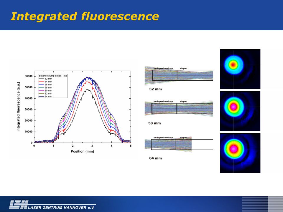
Integrated fluorescence

14
Spot diameters from integrated fluorescence Crystals are slightly different doped Characterization of the incoming crystals

15
Incoming inspection of the components Since small qualitative differences seem to have a big effect, this is the only way to guarantee the reproducibility of the system ! Development of characterization facilities for –Crystals –Mirrors and lenses –Pump diodes

16
Crystal characterization so far: longitudinal measurement of the fluorescence upcoming: transversal measurement of the absorption Direct measurement of the doping concentration Possibility of „scanning“ the crystal to find doping gradients

17
Mirror characterisation automated polarimeterpolarization analysis software

18
Diode characterisation Automated test facility for measuring –Slope –Spectral FWHM at different currents –Spectrum at different currents –Peak wavelength –Threshold –Operating current for 45 W optical output

19
Content Setup Status in October 2007 Status now Characterization work –Crystals –Mirrors –Diodes System improvement / outlook –Crystal cooling

20
Improvements: new pump chambers More homogeneous cooling at the crystal surface ? Higher cooling efficiency ? Less acoustic noise ?

21
Improvements: new pump chambers

22
Calculated thermal lens for old chamber: 0.027 dpt/W Calculated thermal lens for new chamber: 0.025 dpt/W

23
Test setup

24
Improvements: new pump chambers

25
Summary System runs with lower output power and more pump power than 6 month before Reason: probably lower doped crystals We have to take care that all incoming components are well characterized and of the same high quality Ideas on system improvement (pump chambers) are going to be checked
 are going to be checked")
26
Thank you for your attention !

27
Improvements: non-conventional cut crystals + good birefringence compensation with quarz rotators (adv. LIGO laser: output power: 170 W cw, linear polarized; depolarized power: 1W) -Additional components inside the resonator (Absorption/thermal effects/losses, spots) -Sensitive adjustment 0° 5° 7°
 -Additional components inside the resonator (Absorption/thermal effects/losses, spots) -Sensitive adjustment 0° 5° 7°.")
28
Improvement: non-conventional cut crystals Reduction of birefringence is possible by use of crystals, which are cut in [100]- or [110]-direction instead of [111]-direction 1) Birefringence depends on the angle between crystal-axis and polarization-axis 1) I. Shoji et al: Appl. Phys. Lett., Vol. 80, No. 17, 29 April 2002
![Improvement: non-conventional cut crystals Reduction of birefringence is possible by use of crystals, which are cut in [100]- or [110]-direction instead of [111]-direction 1) Birefringence depends on the angle between crystal-axis and polarization-axis 1) I.](http://images.slideplayer.com/24/7011146/slides/slide_28.jpg "Shoji et al: Appl. Phys. Lett., Vol. 80, No. 17, 29 April")
29
Improvements: pump combiners 7x200µm input : 1 up to 700 W input power transfer efficiency > 93% Source: ITF

30
Integrated fluorescence

31
RIN (unstabilized, locked laser)
")
32
Spots on surfaces and coatings Spots on coatings and optical components knocked out the system several times Bring as few dust as possible to the laser table Check quality of incoming components ca. 150 µm

Similar presentations


. The shaded atoms make up a unit cell of the structure. The aluminum atom inside the.>")

 NSF-supported UF/IAP collaborative project Methods and Instruments for High-Precision Characterization of LIGO Optical Components>")
>")


 near 1.3 µm Didier Mondelain 1, Agnès Perrin 2, Samir Kassi 1 & Alain Campargue.>")


