Download presentation
Presentation is loading. Please wait.

1
Oscillators with LC Feedback Circuits

2
LC Feedback elements are used for the generation of higher frequencies of oscillation. Because of lower unity gain frequency of most op amps, discrete transistors are often used as the gain elements in LC Feedback oscillators. Colpitts, Clapp, Hartley, Armstrong and Crystal controlled oscillators are the examples

3
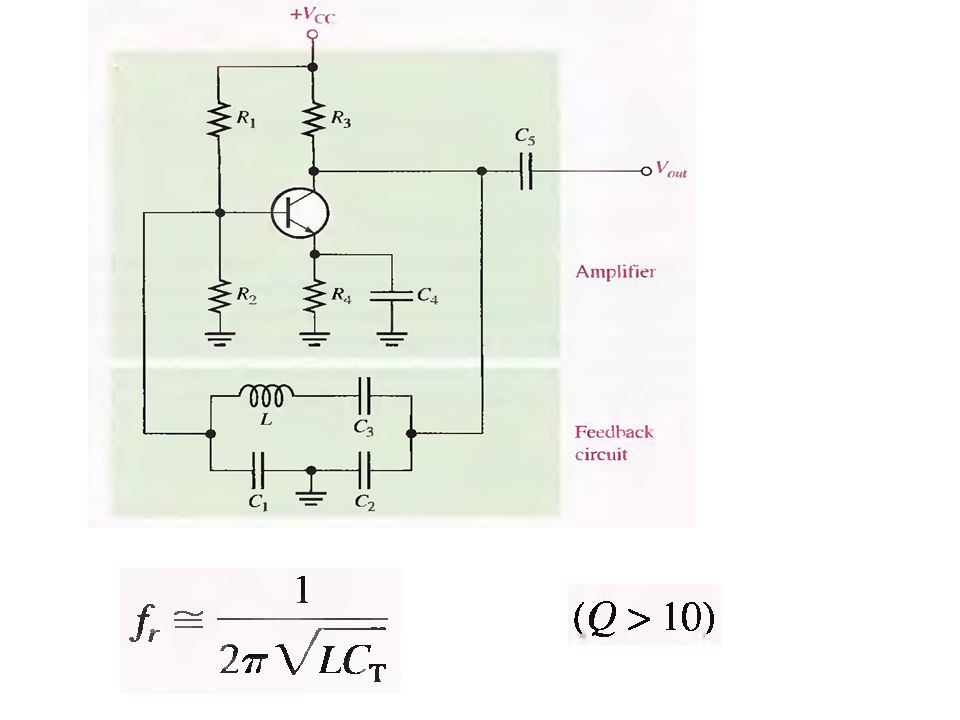
The Colpitts Oscillator LC feedback circuit provides the required phase shift and acts as resonant filter that passes only the desired frequency of oscillation.

4
Conditions for Oscillation and Startup Values of C1 and C2 determine the attenuation as or But for Oscillation

5
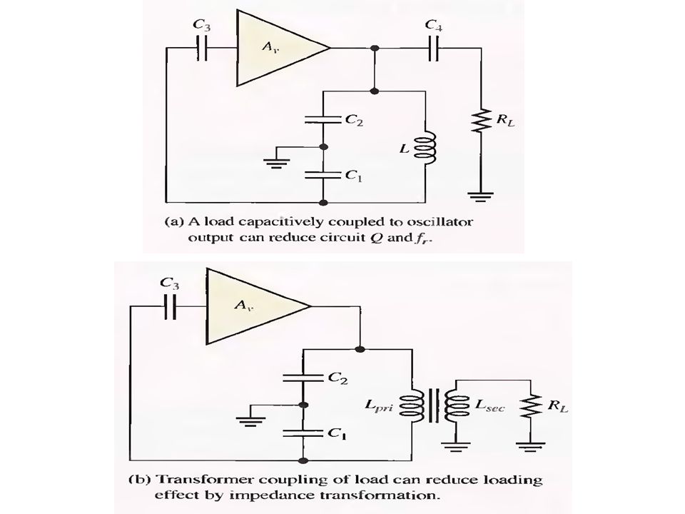
For the oscillator to be self starting, OR Loading Effect on Feedback Circuit Input impedance of the amplifier acts as a load on the resonant feedback circuit and reduces the quality factor of the circuit When Q>10, When Q<10, the resonant frequency is significantly reduced

6
To avoid this loading effect, we can use JFET instead of BJT as it has very high input impedance as compared to BJT.

8
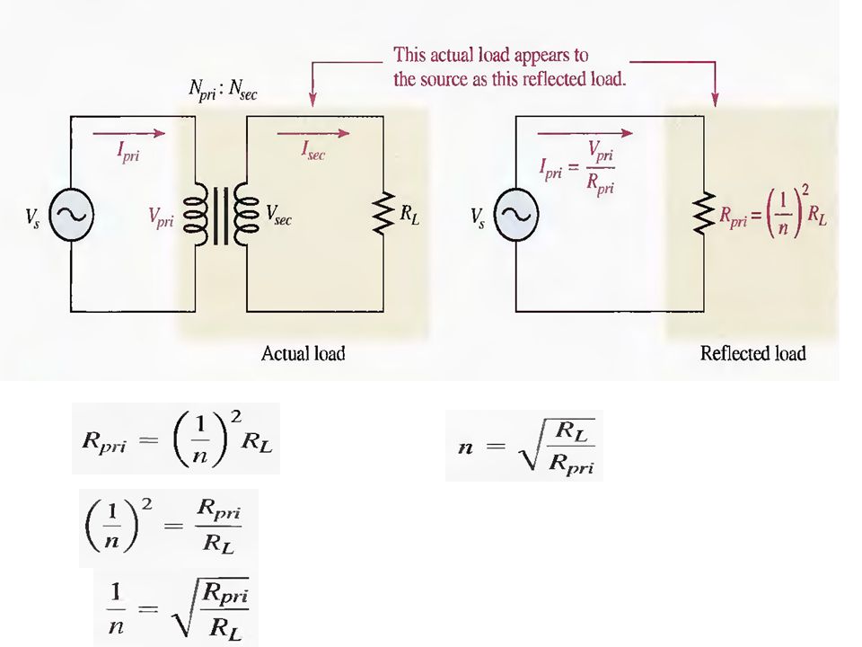
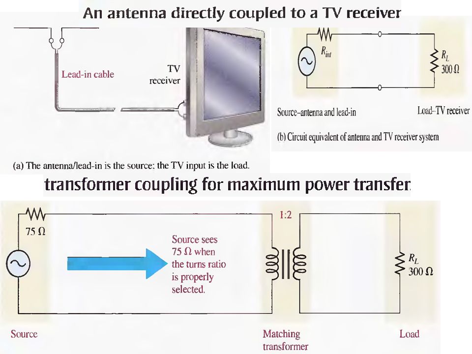
The concept of Reflected Load and Impedance Matching using Transformer Coupling

11
Matching Audio amplifier with an output resistance of 800 ohm to an 8 ohm speaker using transformer coupling

12
The Clapp Oscillator Clapp oscillator is a variation of Colpitts An additional capacitance C 3 in series with the inductor This new capacitance is in series with C 1 and C 2 within the tank circuit Total capacitance is given by

14
If C 3 is much smaller than C 1 and C 2,then C 3 almost entirely controls the resonant frequency Since one end of each of C 1 and C 2 is grounded, junction capacitance and other stray capacitances appear in parallel with these altering their values C 3 is not affected yet and hence helps to provide a more accurate and stable frequency of oscillation

15
The Hartley Oscillator

16
OR Loading Effect is the same as in the case of Colpitts, i.e, to reduce the quality factor hence reducing the resonant frequency.

17
The Armstrong Oscillator

18
Uses transformer coupling for feedback provision of the signal voltage. Sometimes called tickler oscillator in reference to transformer secondary of tickler coil. Less common as compared to previous ones mainly because of transformer size and cost. The frequency of oscillation is set by the inductance of primary winding, L pri in parallel with C 1

19
Crystal Controlled Oscillators Most stable and accurate type of feedback oscillators Exhibits a very high Q (values of several thousand are typical) Piezoelectric crystal is used in the feedback loop for the frequency control Quartz crystal is normally used in electronic applications in the form of a quartz wafer Piezoelectric Effect: when a changing mechanical stress is applied across the crystal to cause it to vibrate, a voltage is developed at the frequency of mechanical vibration Conversely when an ac voltage is applied across the crystal, it vibrates at the frequency of applied voltage The greatest vibration occurs at the natural resonant frequency.
 Piezoelectric crystal is used in the feedback loop for the frequency control Quartz crystal is normally used in electronic applications in the form of a quartz wafer Piezoelectric Effect: when a changing mechanical stress is applied across the crystal to cause it to vibrate, a voltage is developed at the frequency of mechanical vibration Conversely when an ac voltage is applied across the crystal, it vibrates at the frequency of applied voltage The greatest vibration occurs at the natural resonant frequency.")
20
Natural resonant frequency is determined by the physical dimensions and by the way the crystal is cut. Quartz wafer is mounted between two electrodes and enclosed in a protective can Series-Parallel RLC circuit can operate either in series or parallel resonance

21
At the series resonance, the inductive reactance is cancelled by the reactance of C S and now R S determines the impedance of the crystal Parallel resonance occurs when the inductance reactance and reactance of C m are equal Parallel resonant frequency is usually at least 1kHz higher than the series resonant frequency

22
Crystal used as series resonant circuit Maximum feedback is provided at series resonant frequency where impedance of the crystal is minimum. C C is used to fine tune the oscillator frequency by pulling the resonant frequency of the crystal slightly up or down

23
Crystal used as parallel resonant circuit (modified Colpitts configuration) Impedance of the crystal is maximum at parallel resonance and maximum voltage is develops across the capacitors The voltage across the capacitor C 1 is fed back to the input
 Impedance of the crystal is maximum at parallel resonance and maximum voltage is develops across the capacitors The voltage across the capacitor C 1 is fed back to the input")
24
Modes of Oscillation in the Crystals There are two modes of oscillation Fundamental Mode : It is the lowest natural resonant frequency of oscillation. It depends upon the crystal mechanical dimensions, type of cut and inversely proportional to the thickness of crystal slab. Upper limit on fundamental frequency is set by the thickness of crystal slab as it cannot be cut too thin without fracturing. For most crystals, this upper limit is less than 20MHz. Overtone Mode : Overtones are the approximate integer multiples of the fundamental frequency Usually these are the odd multiples of the fundamental

Similar presentations