Download presentation
Presentation is loading. Please wait.

1
Chapter 8 Second-Order Circuits
Circuit Theory Chapter 8 Second-Order Circuits Copyright © The McGraw-Hill Companies, Inc. Permission required for reproduction or display.

2
Second-Order Circuits Chapter 8
8.1 Examples of 2nd order RLC circuit 8.3 The source-free parallel RLC circuit 8.5 Step response of a parallel RLC 8.2 The source-free series RLC circuit 8.4 Step response of a series RLC circuit

3
8.1 Examples of Second Order RLC circuits (1)
What is a 2nd order circuit? A second-order circuit is characterized by a second-order differential equation. It consists of resistors and the equivalent of two energy storage elements. RLC Series RLC Parallel RL T-config RC Pi-config

4
8.3 Source-Free Parallel RLC Circuits (1)
Let v(0) = V0 Apply KCL to the top node: Taking the derivative with respect to t and dividing by C The 2nd order of expression
 = V0. Apply KCL to the top node: Taking the derivative with respect to t and dividing by C. The 2nd order of expression.")
5
8.3 Source-Free Parallel RLC Circuits (2)
There are three possible solutions for the following 2nd order differential equation: 1. If a > wo, over-damped case where 2. If a = wo, critical damped case where 3. If a < wo, under-damped case where

6
8.3 Source-Free Parallel RLC Circuits (3)
Example 3 Refer to the circuit shown below Find v(t) for t > 0. Please refer to lecture or textbook for more detail elaboration. Answer: v(t) = 66.67(e–10t – e–2.5t) V
 for t > 0. Please refer to lecture or textbook for more detail elaboration. Answer: v(t) = 66.67(e–10t – e–2.5t) V.")
10
8.5 Step-Response Parallel RLC Circuits (1)
The step response is obtained by the sudden application of a dc source. The 2nd order of expression It has the same form as the equation for source-free parallel RLC circuit. The same coefficients (important in determining the frequency parameters). Different circuit variable in the equation.
. Different circuit variable in the equation.")
11
8.5 Step-Response Parallel RLC Circuits (2)
The solution of the equation should have two components: the transient response vt(t) & the steady-state response vss(t): The transient response it is the same as that for source-free case (over-damped) (critical damped) (under-damped) The steady-state response is the final value of i(t). iss(t) = i(∞) = Is The values of A1 and A2 are obtained from the initial conditions: i(0) and di(0)/dt.
 & the steady-state response vss(t): The transient response it is the same as that for source-free case. (over-damped) (critical damped) (under-damped) The steady-state response is the final value of i(t). iss(t) = i(∞) = Is. The values of A1 and A2 are obtained from the initial conditions: i(0) and di(0)/dt.")
12
8.5 Step-Response Parallel RLC Circuits (3)
Example 5 Find i(t) and v(t) for t > 0 in the circuit shown in circuit shown below: Please refer to lecture or textbook for more detail elaboration. Answer: v(t) = Ldi/dt = 5x20sint = 100sint V
 and v(t) for t > 0 in the circuit shown in circuit shown below: Please refer to lecture or textbook for more detail elaboration. Answer: v(t) = Ldi/dt = 5x20sint = 100sint V.")
16
8.2 Source-Free Series RLC Circuits (1)
The solution of the source-free series RLC circuit is called as the natural response of the circuit. The circuit is excited by the energy initially stored in the capacitor and inductor. The 2nd order of expression How to derive and how to solve?

17
8.2 Source-Free Series RLC Circuits (3)
There are three possible solutions for the following 2nd order differential equation: General 2nd order Form where => The types of solutions for i(t) depend on the relative values of a and w.
 depend on the relative values of a and w.")
18
8.2 Source-Free Series RLC Circuits (4)
There are three possible solutions for the following 2nd order differential equation: 1. If a > wo, over-damped case where 2. If a = wo, critical damped case where 3. If a < wo, under-damped case where

19
8.2 Source-Free Series RLC Circuits (5)
Example 1 If R = 10 Ω, L = 5 H, and C = 2 mF in 8.8, find α, ω0, s1 and s2. What type of natural response will the circuit have? Please refer to lecture or textbook for more detail elaboration. Answer: underdamped

21
8.2 Source-Free Series RLC Circuits (6)
Example 2 The circuit shown below has reached steady state at t = 0-. If the make-before-break switch moves to position b at t = 0, calculate i(t) for t > 0. Please refer to lecture or textbook for more detail elaboration. Answer: i(t) = e–2.5t[5cos1.6583t – 7.538sin1.6583t] A
 for t > 0. Please refer to lecture or textbook for more detail elaboration. Answer: i(t) = e–2.5t[5cos1.6583t – 7.538sin1.6583t] A.")
25
8.4 Step-Response Series RLC Circuits (1)
The step response is obtained by the sudden application of a dc source. The 2nd order of expression The above equation has the same form as the equation for source-free series RLC circuit. The same coefficients (important in determining the frequency parameters). Different circuit variable in the equation.
. Different circuit variable in the equation.")
26
8.4 Step-Response Series RLC Circuits (2)
The solution of the equation should have two components: the transient response vt(t) & the steady-state response vss(t): The transient response vt is the same as that for source-free case (over-damped) (critically damped) (under-damped) The steady-state response is the final value of v(t). vss(t) = v(∞) The values of A1 and A2 are obtained from the initial conditions: v(0) and dv(0)/dt.
 & the steady-state response vss(t): The transient response vt is the same as that for source-free case. (over-damped) (critically damped) (under-damped) The steady-state response is the final value of v(t). vss(t) = v(∞) The values of A1 and A2 are obtained from the initial conditions: v(0) and dv(0)/dt.")
27
8.4 Step-Response Series RLC Circuits (3)
Example 4 Having been in position for a long time, the switch in the circuit below is moved to position b at t = 0. Find v(t) and vR(t) for t > 0. Please refer to lecture or textbook for more detail elaboration. Answer: v(t) = {10 + [(–2cos3.464t – sin3.464t)e–2t]} V vR(t)= [2.31sin3.464t]e–2t V
 and vR(t) for t > 0. Please refer to lecture or textbook for more detail elaboration. Answer: v(t) = {10 + [(–2cos3.464t – sin3.464t)e–2t]} V. vR(t)= [2.31sin3.464t]e–2t V.")
31
1)determine the qualitative form of the response vc(t) as being either overdamped, underdamped, or critically damped. Underdamped Overdamped Underdamped Critically damped

32
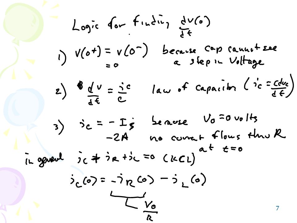
2) Determine the initial value of Vr(t), and dVr(t)/dt, and the final value of Vr(t)
Vr(0) = 6V; dVr(0)/dt = 3V/s; Vr(infinity) = 0V
 = 6V; dVr(0)/dt = 3V/s; Vr(infinity) = 0V.")
33
3) For both the inductor current and voltage, determine their initial values, the initial values of their derivatives, and their final values. The capacitor has 9 J of stored energy before the switch closes.

34
4)Plot the inductor current iL(t) and inductor voltage vL(t) for time t = -0.1 seconds to t = 3 seconds. Confirm your results using a circuit simulator. iL(t) = sin(4.15t) e -1.67t , t>=0
 = sin(4.15t) e -1.67t , t>=0.")
Similar presentations