Download presentation
Presentation is loading. Please wait.

1
Are you using the right CT's and PT's for your application
Are you using the right CT's and PT's for your application? John Levine, P.E. Levine Lectronics and Lectric GE Multilin/ Instrument Transformers, Inc.

2
Current & Voltage Transformer Basics (IEEE Standards)
")
3
Agenda Current Transformers Voltage Transformers
Required Information for Specifying CTs & VTs Take Home Rules” for CTs & VTs Configure Tool for CTs and VTs Products and tour of Plant Applications where used FT Switches Configure Tool for FT Switches

4
Why use Instrument Transformers?
Circuit Isolation Reduce voltage and currents to reasonable working levels. Phasor combinations for summing and measuring power

5
& VOLTAGE TRANSFORMERS
CURRENT TRANSFORMERS & VOLTAGE TRANSFORMERS TYPES OF C.T. AND V.T. CONSTRUCTION The most common type of C.T. construction is the `DOUGHNUT' type. It is constructed of an iron toroid, which forms the core of the transformer, and is wound with secondary turns. Secondary Winding Primary Conductor Iron Core The `doughnut' fits over the primary conductor, which constitutes one primary turn. If the toroid is wound with 240 secondary turns, then the ratio of the C.T. is 240 : 1 or 1200 : 5A The continuous rating of the secondary winding is normally 5 AMPS in North America, and 1 AMP or 0.5 AMP in many other parts of the world. This type of `doughnut' C.T. is most commonly used in circuit breakers and transformers. The C.T. fits into the bushing `turret', and the porcelain bushing fits through the centre of the `doughnut'. Up to four C.T.'s of this type can be installed around each bushing of an oil circuit breaker. This arrangement is shown in the following diagram.

6
_____________________
Transformer ratio (TR) Primary Current Secondary Current Transformer Ratio = _____________________ Primary Current (100 amps) Secondary Current (5 amps) 100 5 ___ = 100:5 or 20:1
 Primary Current. Secondary Current. Transformer Ratio = _____________________. Primary Current. (100 amps) Secondary Current. (5 amps) ___. = 100:5 or 20:1.")
7
Polarity Remember: Primary current into “polarity” =
Direction of Secondary Current Direction of Primary Current Secondary Polarity Marks IEEE X1 S1 IEC Primary Polarity Marks IEEE H1 IEC P1 Remember: Primary current into “polarity” = Secondary current out of “polarity”

8
Polarity Remember: Primary current into “non-polarity” =
Direction of Secondary Current Secondary Polarity Marks IEEE X1 S1 IEC Primary Polarity Marks IEEE H1 IEC P1 Direction of Primary Current Remember: Primary current into “non-polarity” = Secondary current out of “non-polarity”

9
G30 typical wiring

10
What is your application?
If your application is metering , how high do I need to go in current? 2 times ? If your application is protective relaying, how high do I need to go in current? 20 times ?

11
CT Rating Factor (RF) -- IEEE
Rated current x (RF) = Maximum continuous current carrying capability: Without exceeding temperature limits Without loss of published accuracy class Typical rating factors , 1.33, 1.5, 2.0, 3.0, 4.0
 = Maximum continuous current carrying capability: Without exceeding temperature limits. Without loss of published accuracy class. Typical rating factors , 1.33, 1.5, 2.0, 3.0, 4.0.")
12
CT Rating Factor (RF) -- IEEE
IEEE C57.13 Accuracy BX.X RF 4.0 0.60 0.6% Accuracy Region 0.30 0.3% Accuracy Region Accuracy Class - % 10% 100% 200% 300% 400% 0.30 0.60 1.0 2.0 3.0 4.0 Rating Factor

13
Short-Time Thermal Current Rating
One (1) – second thermal rating Expressed as value of RMS primary current Main influencing factor: CT primary & secondary wire size Can be converted to thermal rating for any time period (t) up to five (5) seconds: I1-sec t
 – second thermal rating. Expressed as value of RMS primary current. Main influencing factor: CT primary & secondary wire size. Can be converted to thermal rating for any. time period (t) up to five (5) seconds: I1-sec t.")
14
Difference in % is known as the “Accuracy”
CT Metering Accuracy = Actual secondary current Rated secondary current Difference in % is known as the “Accuracy” of the CT

15
IEEE CT Metering Accuracy
Class ( * ) Application High Accuracy Metering 0.15S “Special” High Accuracy Metering Revenue Metering Indicating Instruments Indicating Instruments * All accuracy classes defined by IEEE C57.13 or C * Accuracy classes include both ratio & phase angle error
 Application High Accuracy Metering. 0.15S Special High Accuracy Metering. 0.3 Revenue Metering. 0.6 Indicating Instruments. 1.2 Indicating Instruments. * All accuracy classes defined by IEEE C57.13 or C * Accuracy classes include both ratio & phase angle error.")
16
IEEE CT Metering Accuracy
Burden Load connected to CT secondary Includes devices & connecting leads Expressed in ohms Standard values = B0.1, B0.2, B0.5, B0.9, B1.8 E0.04, E0.2 All burdens defined by IEEE C57.13 or C for 60 Hz only

17
IEEE CT Metering Accuracy
Standard IEEE CT Burdens (5 Amp) (Per IEEE Std. C & C ) E0.2 E0.04 0.2 0.04 5 1 1.0
 (Per IEEE Std. C & C ) E0.2. E")
18
CT CLASSIFICATION for Metering
A current transformer for metering purposes may typically have an accuracy of 0.3%. The C.T. must maintain this accuracy for normal load currents, provided the rated burden on the C.T. is not exceeded. It is quite acceptable, and in fact desirable, for the C.T. to saturate when fault current flows. The accuracy for a typical metering C.T. is specified as: 0.3 M 0.9 O.3% METERING O.9 OHMS BURDEN This metering C.T. has an accuracy of 0.3% when the connected burden does not exceed 0.9 OHMS.

19
IEEE CT Metering Accuracy
“Accuracy” expressed as: Typical Examples + = Accuracy Class (0.3, 0.6, 1.2) (*) Burden (Ohms) (B0.1, B0.2, B0.5, B0.9, B1.8) 0.3B0.2 0.6B0.9 1.2B1.8 0.15E0.2 (0.15*, 0.15S^) E0.2, E0.04) * Accuracy class is stated at 100% rated current * At 10% rated current, twice the error is allowed (5% for 0.15 class) ^ Accuracy class is stated at 100% to 5% rated current
 (*) Burden (Ohms) (B0.1, B0.2, B0.5, B0.9, B1.8) 0.3B B B E0.2. (0.15*, 0.15S^) E0.2, E0.04) * Accuracy class is stated at 100% rated current. * At 10% rated current, twice the error is allowed (5% for 0.15 class) ^ Accuracy class is stated at 100% to 5% rated current.")
20
IEEE CT Metering Accuracy
IEEE C57.13 Accuracy BX.X; RF 4.0 0.60 0.6% AccuracyRegion 0.30 0.3% Accuracy Region Accuracy Class - % 10% 100% 200% 300% 400% 0.30 No accuracy guaranteed at current levels less than 10% 0.60 1.0 2.0 3.0 4.0 Rating Factor

21
IEEE CT Metering Accuracy
CT Parallelogram – IEEE C57.13 0.3 class parallelogram 10% 100% 0.6 class parallelogram Note: Burden must be specified Out of 0.3% Class

22
IEEE CT Metering Accuracy
CT Parallelogram – IEEE C57.13 0.3 class parallelogram 10% 100% 0.6 class parallelogram Note: Burden must be specified Corrected to 0.3% Class

23
IEEE CT Metering Accuracy
IEEE C Accuracy E0.04, E0.20; BX.X; RF4.0 0.60 0.30 0.15% Accuracy Region 0.15 0.3% AccuracyRegion Accuracy Class - % 5% 100% 200% 300% 400% 0.15 0.30 No accuracy guaranteed at current levels less than 5% 0.60 1.0 2.0 3.0 4.0 Rating Factor

24
IEEE CT Metering Accuracy
IEEE C Accuracy E0.04, E0.20; BX.X, RF4.0 0.60 0.30 0.15% Accuracy Region 0.15 Accuracy Class - % 5% 100% 200% 300% 400% 0.15 0.30 No accuracy guaranteed at current levels less than 5% 0.60 1.0 2.0 3.0 4.0 Rating Factor

25
Standard Relay Accuracy Classes
IEEE CT Relay Accuracy Standard Relay Accuracy Classes C or T100 C or T200 C or T400 C or T800 What do these mean?

26
IEEE CT Relay Accuracy Relay class (C or T___ ) designates minimum secondary terminal volts… At 20 times rated current Without exceeding 10% ratio error Into a maximum specified burden Now that everyone is totally confused let’s look at some simple examples …

27
CT CLASSIFICATION for RELAYING
Protection Class CT’s - Must supply 20 times rated current 10 C 400 Format Accuracy Voltage at 20 times CT Letter CT Classification for relaying Over the years many standards for CT classification have been developed in North America and Europe. Protection class CT’s are assumed to be able to supply 20 times its rated secondary current to the relay. That means for a 5 amp rated secondary the CT must be able to supply 100 Amps of current, and for a 1 amp rated secondary the CT must be able to supply 20 Amps of current. The operating principals of CT’s are specified in a format such as this. The first number represents the maximum amount of error, listed in as a percentage, that this CT will produce. Therefore, the 10 in our example stands for no more then 10 percent error. The second item, which is always a letter, can either be a T, C, K, L, or H. If the letter is a T which stands for “test”, it means that the CT accuracy can only be determined by testing the CT. Current transformers with non-distributed windings fit in this category. If the letter is a C or a K which stands for “Calculated”, it means the CT accuracy can be determined by performing calculation using given excitation characteristics. CTs with fully distributed windings, (bushing CT’s for instance) fit in this category. If the letter is an L, this indicates that the CT has a “Low internal secondary impedance,” If the letter is an H, this indicates that the CT has a “high internal secondary impedance,” T = Determined by test C = Calculated K = Calculated L = Low internal secondary impedance H = High internal secondary impedance
 fit in this category. If the letter is an L, this indicates that the CT has a Low internal secondary impedance, If the letter is an H, this indicates that the CT has a high internal secondary impedance, T = Determined by test. C = Calculated. K = Calculated. L = Low internal secondary impedance. H = High internal secondary impedance.")
28
IEEE CT Relay Accuracy C or T100 example Secondary current
100 amps (20 x 5) X1 X2 Burden of Devices () Primary current 24,000 amps (20 x 1200) Total Ext Burden 1.0 Terminal Volts = 100 CT 1200:5 C or T100 Burden of Leads () Terminal Volts = (20 times rated) (Total external burden) 100 Volts = (100 amps) (1.0 )
 X1. X2. Burden of. Devices () Primary current. 24,000 amps. (20 x 1200) Total Ext. Burden. 1.0 Terminal Volts = 100. CT. 1200:5. C or T100. Burden of. Leads () Terminal Volts = (20 times rated) (Total external burden) 100 Volts = (100 amps) (1.0 )")
29
IEEE CT Relay Accuracy C or T200 example Secondary current
100 amps (20 x 5) X1 X2 Burden of Devices () Primary current 24,000 amps (20 x 1200) Total Ext Burden 2.0 Terminal Volts = 200 CT 1200:5 C or T200 Burden of Leads () Terminal volts = (20 times rated) (Total external burden) 200 Volts = (100 amps) (2.0 )
 X1. X2. Burden of. Devices () Primary current. 24,000 amps. (20 x 1200) Total Ext. Burden. 2.0 Terminal Volts = 200. CT. 1200:5. C or T200. Burden of. Leads () Terminal volts = (20 times rated) (Total external burden) 200 Volts = (100 amps) (2.0 )")
30
IEEE CT Relay Accuracy Standard IEEE CT Burdens (5 Amp) (Per IEEE Std. C )
 (Per IEEE Std. C )")
31
IEEE CT Relay Accuracy Excitation curve includes
voltage required to overcome internal resistance (DCR) of CT. Approximately 32 volts. 10% ratio error = (20 x 5) (10%) = (100) (0.10) = 10 amps This Ct is not a C200. Since you can only produce 209 volts, when you take the 32 volts from internal resistance you only have 177 Volts so you might rate this CT as a C150. How many terminal volts would you estimate this CT can produce?
 of CT. Approximately 32 volts. 10% ratio error = (20 x 5) (10%) = (100) (0.10) = 10 amps. This Ct is not a C200. Since you can only produce 209 volts, when you take the 32 volts from internal resistance you only have 177 Volts so you might rate this CT as a C150. How many terminal volts. would you estimate. this CT can produce")
32
CT Burden Calculation How do we calculate this? Secondary current
X1 X2 Primary Current Burden of Devices () Total Burden ZT CT Burden of Leads ()
 Total. Burden ZT. CT. Burden of. Leads ()")
33
CT Burden Calculation ZT = RCT + RL + ZB
ZT = Total burden in ohms (vector summation of resistance and inductance components) RCT = CT secondary resistance in deg C (DCR) RL = Resistance of leads in ohms (Total loop distance) ZB = Device impedance in ohms Assumption: 3 phase CTs are “Y” connected
 RCT = CT secondary resistance in deg C (DCR) RL = Resistance of leads in ohms (Total loop distance) ZB = Device impedance in ohms. Assumption: 3 phase CTs are Y connected.")
34
GE Multilin Electronic Relay Burden
VA = VI. V= IR, So 0.2 = I*I*R. .2/25 = .008 ohms

35
100:5 C.T. Secondary Winding Resistance = .062 ohm
Resistance of Cable from C.T. to Relay and back = .1 ohms Resistance of Relay Coil = .02 ohms Total Resistance = .182 ohms .062 .02 .1 If we have a fault of 2,000 amps and the C.T. ratio is 100:5 then the C.T. secondary current is 100 amps. Therefore we must be able to produce a total voltage of 100 amps x .182 ohms = 18.2 Volts. To prevent CT saturation, select a CT with a knee point above 18.2 Volts. In this example the resistance of the C.T. secondary circuit, or C.T. burden is: C.T. Secondary Winding Resistance = 1 OHM Resistance of Cable from C.T. to Relay = 2 OHMS Resistance of Relay Coil = 2 OHMS Total Resistance of C.T. Secondary Circuit = 5 OHMS If the fault current is 12,000 Amps, and the C.T. ratio is 1200 : 5A, then the C.T. secondary current is 50 Amps. At this secondary current and the above C.T. burden of 5 OHMS, the C.T. must produce a terminal voltage of 250 volts. For the C.T. to operate with good accuracy, without saturating for the maximum fault current, the knee point must be well above 250 volts.

36
1000:5 C.T. Secondary Winding Resistance = .32 ohm
is a 1000 to 5 CT, Class C100 1000:5 C.T. Secondary Winding Resistance = .32 ohm Resistance of Cable from C.T. to Relay and back = .1 ohms Resistance of Relay Coil = .008 ohms Total Resistance = .428 ohms .32 .008 .1 If we have a fault of 20,000 amps and the C.T. ratio is 1000:5 then the C.T. secondary current is 100 amps. Therefore we must be able to produce a total voltage of 100 amps x .428 ohms = 42.8 Volts. To prevent CT saturation, select a CT with a knee point above 42.8 Volts. What happens if the fault current is 35,000 amps? In this example the resistance of the C.T. secondary circuit, or C.T. burden is: C.T. Secondary Winding Resistance = 1 OHM Resistance of Cable from C.T. to Relay = 2 OHMS Resistance of Relay Coil = 2 OHMS Total Resistance of C.T. Secondary Circuit = 5 OHMS If the fault current is 12,000 Amps, and the C.T. ratio is 1200 : 5A, then the C.T. secondary current is 50 Amps. At this secondary current and the above C.T. burden of 5 OHMS, the C.T. must produce a terminal voltage of 250 volts. For the C.T. to operate with good accuracy, without saturating for the maximum fault current, the knee point must be well above 250 volts.

37
Factors Influencing CT Accuracy
Frequency “Low frequency” and “High accuracy” are not friends!! Current Ratio “Low ratio” and “high accuracy” are not friends!! Burden “High burden” and “High Accuracy” are not friends!!

38
Tips for Avoiding CT Saturation
Use higher ratio CTs Use separate set of high ratio CTs for high fault current tripping Reduce secondary burden Select low burden relays & meters Distribute single phase burdens among phases Increase size of secondary leads Reduce length of secondary leads Use “step down” auxiliary CTs

39
Potential Transformers

40
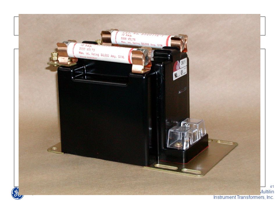
Definitions Voltage Transformer (VT)
An instrument transformer used to reflect a primary voltage into a secondary voltage through a magnetic medium. Always connected in parallel with primary conductor across a circuit load. Secondary (measuring) voltage is usually 115 or 120 volts nominally. The secondary voltage level is selected for ease of measurement and safety. Control Power Transformer (CPT) Designed to provide power for contractors, relays and devices with high inrush currents, Regulation is not as critical.
 voltage is usually 115 or 120 volts nominally. The secondary voltage level is selected for ease of measurement and safety. Control Power Transformer (CPT) Designed to provide power for contractors, relays and devices with high inrush currents, Regulation is not as critical.")
42
POTENTIAL TRANSFORMERS
VP 4200/120 = 35/1 2400/120 = 20/1 Potential Transformers Potential transformers are used to isolate and step down and accurately reproduce the scaled voltage for the relay. The primary side of a PT needs to have the System voltage, symbolized as Vp, applied across the input terminals as shown here. The Secondary side of the PT will then accurately replicates a scaled down version the primary voltage over a defined voltage range . The secondary voltage is symbolized as Vs. There are two types of potential transformers: Electromagnetic voltage transformer and the capacitive voltage transformers. Vs Relay

43
IEEE VT Accuracy Class Metering Accuracy Classes (% error) 0.3
0.6 1.2 0.15 Defined by IEEE C57.13 Applicable from 90% to 110% rated voltage Defined by IEEE C

44
IEEE VT Accuracy Class Metering Accuracy Class Burdens
These standard burden designations have no significance at frequencies other than 60 Hz.

45
IEEE VT Accuracy Class Expressed as: Accuracy Class + Burden Code
0.3 W,X,Y 0.6 Z 1.2 ZZ These standard designations have no significance at frequencies other than 60 Hz.

47
VT Installation Guidelines
Caution: Rated voltage: Do not operate above 110% Line to ground rated: Do not connect line to line Do not use on ungrounded systems w/o consulting factory Rated Frequency: Do not operate below rated frequency w/o consulting factory

48
IEEE VT Groups VT Group No. of Bushing Connection Method
Neutral Grounding Notes 1 2 open Y-Y possible Any Withstand 25% over rated voltage on an emergency basis Withstand 10% over rated voltage continuously. Primary rated for line to line voltage. 3 Y-Y-Y Outdoor, two secondary windings. Withstand 10% over rated voltage continuously. 4A Y-Y Effectively Withstand 10% over rated voltage continuously & 25% on an emergency basis. For operation at 100% rated voltage. 4B Y-Broken Corner Non-effectively Withstand 10% overvoltage continuously. For operation at 58% rated voltage. 5 Outdoor. Withstand 40% over rated voltage for 1 minute and 10% over rated voltage continuously

49
VT Typical Connections
Open Delta Connection (2) Double Bushing VTs Y – Y Connection (3) Single Bushing VTs
 Double Bushing VTs. Y – Y Connection. (3) Single Bushing VTs.")
50
Ferroresonance Possible with Y connected grounded VTs on ungrounded power systems A VT is an inductive component Capacitance to ground exists in the system When they match ferroresonance may occur May cause higher VT voltages & saturation Possible results -- High VT currents Overheating VT failure

51
Ferroresonance Recommended reading:
“Ferroresonance of Grounded Potential Transformers on Ungrounded Power Systems” AIEE Power Apparatus & Systems, Aug 1959, pg , by Karlicek and Taylor

52
Ferroresonance Damping
Preferred method Non effectively grounded system Y – Broken Corner VT connection Voltage relay to detect ground fault 0 normal condition 3 times normal L-N phase ground fault Ferroresonance damping resistor RFR

53
Ferroresonance Damping
Preferred method Y-Y/Broken Corner Connection Double secondary VT (1) Relaying / Metering (1) Ground fault detection and ferroresonance damping
 Relaying / Metering. (1) Ground fault detection. and ferroresonance damping.")
54
Ferroresonance Damping Ferroresonance damping resistor RFR value
Based on 2 variables: Air core inductance of primary winding (La) VT ratio (N) RFR = 100 La / N2 Power rating (watts) of the resistor is a system related problem. General recommendation is 50% of VA rating of a single VT.
 VT ratio (N) RFR = 100 La / N2. Power rating (watts) of the resistor is a system related problem. General recommendation is 50% of VA rating of a single VT.")
55
for Specifying CTs & VTs
Required Information for Specifying CTs & VTs

56
Current Transformer (CT) RFQ Specification
Environment: ___Indoor ___Outdoor System Voltage (kV) 0.6 0.72 3.6 5.0 7.2 8.7 12 15 24 25 34.5 Power Frequency (kV) 4 3 10 19 20 26 28 34 50 40 70 BIL (kV) 10 40 60 75 110 125 150 200 Standard (Check one) IEEE __ IEC __ IEC __ IEEE __ CT Application: ___Metering ___Protection Dimensions: ___ Inches ___ mm Max. Outside: L ______ x W ______ x D ______ CT Window: Round: ______ Diameter; Rectangular: L ______ x W ______ ; Primary Bar: _____ Current Ratio: _______ : 5 _______ : 1 Continued next slide
 Power Frequency (kV) BIL (kV) Standard (Check one) IEEE __. IEC __. IEC __. IEEE __. CT Application: ___Metering ___Protection. Dimensions: ___ Inches ___ mm. Max. Outside: L ______ x W ______ x D ______. CT Window: Round: ______ Diameter; Rectangular: L ______ x W ______ ; Primary Bar: _____. Current Ratio: _______ : 5 _______ : 1. Continued next slide.")
57
Current Transformer (CT) RFQ Specification (Continued)
Accuracy: Indication Only: _____ %, _____VA (Skip metering & protection selections) Metering Class: IEEE: ___0.3 ___0.6 ___1.2 ___2.4 ________Other IEC: ___0.2 ___0.5 ___1.0 ________Other Metering Burden: IEEE (Ohms): ___B0.1 ___B0.2 ___B0.5 ___B0.9 ___B1.8 ______Other IEC (VA): ___ ___ ___ ___ ___ ______Other Protection Class: C______(IEEE) ___VA, ___P___(IEC) Operating Frequency: ___60HZ ___50HZ Rating Factor: ___1.0 ___1.33 ___1.5 ___2.0 ______Other Secondary Connections: ___Terminals ___24 inch leads Outer Insulation: ___Standard ___Cotton tape & varnish ___Polyester tape Insulation Class: ___105 0C (Standard) _____Other Other Special Requirements (dimensional constraints, mounting requirements, …etc): ______________________________________________________________________________
 Metering Class: IEEE: ___0.3 ___0.6 ___1.2 ___2.4 ________Other. IEC: ___0.2 ___0.5 ___1.0 ________Other. Metering Burden: IEEE (Ohms): ___B0.1 ___B0.2 ___B0.5 ___B0.9 ___B1.8 ______Other. IEC (VA): ___2.5 ___5.0 ___10 ___15 ___30 ______Other. Protection Class: C______(IEEE) ___VA, ___P___(IEC) Operating Frequency: ___60HZ ___50HZ. Rating Factor: ___1.0 ___1.33 ___1.5 ___2.0 ______Other. Secondary Connections: ___Terminals ___24 inch leads. Outer Insulation: ___Standard ___Cotton tape & varnish ___Polyester tape. Insulation Class: ___105 0C (Standard) _____Other. Other Special Requirements (dimensional constraints, mounting requirements, …etc): ______________________________________________________________________________.")
58
Voltage Transformer (VT) RFQ Specification
Environment: ___Indoor ___Outdoor System Voltage (kV) 0.6 0.72 3.6 5.0 7.2 8.7 12 15 24 25 34.5 Power Frequency (kV) 4 3 10 19 20 26 28 34 50 40 70 BIL (kV) 10 40 60 75 110 125 150 200 Standard (Check one) IEEE __ IEC __ IEC __ Operating Frequency: ___60HZ ___50HZ Accuracy: IEEE: ___W ___X ___M ___Y ___Z ___ZZ ________Other (Enter 0.3, 0.6, 1.2, or leave blank) IEC: ___10VA ___25VA ___50VA ___100VA ___200VA ___500VA ______Other (Enter 0.2, 0.5, 1.0, or leave blank) Continued next slide
 Power Frequency (kV) BIL (kV) Standard (Check one) IEEE __. IEC __. IEC __. Operating Frequency: ___60HZ ___50HZ. Accuracy: IEEE: ___W ___X ___M ___Y ___Z ___ZZ ________Other. (Enter 0.3, 0.6, 1.2, or leave blank) IEC: ___10VA ___25VA ___50VA ___100VA ___200VA ___500VA ______Other. (Enter 0.2, 0.5, 1.0, or leave blank) Continued next slide.")
59
Voltage Transformer (VT) RFQ Specification (Continued)
Thermal Rating: _______VA (Optional) Primary Voltage: ___1 bushing _________VAC - Phase to neutral ___2 bushing _________VAC - Phase to phase Secondary Voltage: ___120V ___115V ___110V ___100V ___120/3 ___115/3 ___110/3 ___100/3 ___Other _________________ Rated Voltage Factor (RVF) (1 bushing only): ___1.9 for 30s ___1.9 for 8 hours ___Other____________ Fuses: ___Primary ___Secondary ___None (600 – 720 V) ___Primary ___Live parts only ___Switchgear Style ___Unfused (2.5kV – 15kV) Note integral fusing not available above 15kV
 Primary Voltage: ___1 bushing _________VAC - Phase to neutral. ___2 bushing _________VAC - Phase to phase. Secondary Voltage: ___120V ___115V ___110V ___100V. ___120/3 ___115/3 ___110/3 ___100/3. ___Other _________________. Rated Voltage Factor (RVF) (1 bushing only): ___1.9 for 30s ___1.9 for 8 hours ___Other____________. Fuses: ___Primary ___Secondary ___None (600 – 720 V) ___Primary ___Live parts only ___Switchgear Style ___Unfused (2.5kV – 15kV) Note integral fusing not available above 15kV.")
60
Take Home Rule # 1 Never open circuit a current
transformer secondary while the primary is energized CTs are intended to be proportional current devices. Very high voltages can result from open circuiting the secondary circuit of an energized CT. Even very small primary currents can cause damage… Consult the factory if you have questions.

61
Take Home Rule # 2 Never short circuit the secondary of an energized VT VTs are intended to be used as proportional voltage devices. Damaging current will result from short circuiting the secondary circuit of an energized VT.

62
Take Home Rule # 3 Metering applications do not require a “C” class CT
“C” class ratings are specified for protection purposes only. With some exceptions metering class CTs are typically smaller and less expensive.

63
Take Home Rule # 4 CT secondary leads must be added to the CT burden
Electronic relays usually represent very little burden to the CT secondary circuit. In many cases the major burden is caused by the CT secondary leads.

64
Take Home Rule # 5 Never use a 60 Hz rated VT on a 50 Hz System
60 Hz VTs may saturate at lower frequencies and exceed temperature limitations. VT failure is likely…severe equipment damage is possible.

65
Take Home Rule # 6 Exercise caution when connecting grounded VTs
to ungrounded systems Line to ground voltage on any VT may exceed the primary voltage rating during a fault condition… VT must be designed for application.

66
QUESTIONS?

Similar presentations


>")


