Download presentation
Presentation is loading. Please wait.

1
Semester 1 Module 8 Ethernet Switching Andres, Wen-Yuan Liao Department of Computer Science and Engineering De Lin Institute of Technology andres@dlit.edu.tw http://www.cse.dlit.edu.tw/~andres

2
Overview Define bridging and switching Define and describe the content-addressable memory (CAM) table Define latency Describe store-and-forward and cut-through packet switching modes Explain Spanning-Tree Protocol (STP) Define collisions, broadcasts, collision domains, and broadcast domains Identify the Layers 1, 2, and 3 devices used to create collision domains and broadcast domains
 table Define latency Describe store-and-forward and cut-through packet switching modes Explain Spanning-Tree Protocol (STP) Define collisions, broadcasts, collision domains, and broadcast domains Identify the Layers 1, 2, and 3 devices used to create collision domains and broadcast domains")
3
Discuss data flow and problems with broadcasts Explain network segmentation and list the devices used to create segments

4
Outline Ethernet Switching Collision Domains and Broadcast Domains

5
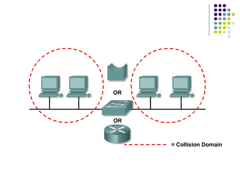
Layer 2 bridging Ethernet is a shared media. Only one node can transmit data at a time. Within Ethernet physical segment more nodes more contention more retransmissions Break the large segment into parts and separate it into isolated collision domains.

6
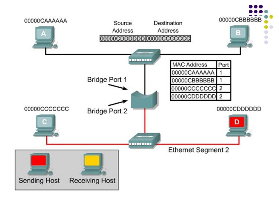
Host A is pinging Host B. The address of Host A is added to its bridge table. The address of Host B has not been recorded yet. Host B processes the ping request and transmits a ping reply back to Host A. The address of Host B is added to its bridge table. Host A is now going to ping Host C. The address of Host C has not been recorded yet. Host C processes the ping request and transmits a ping reply back to Host A. The address of Host C is added to its bridge table. When Host D transmits data, its MAC address will also be recorded in the bridge table.

8
Layer 2 switching Generally, a bridge has only two ports and divides a collision domain into two parts. All decisions made by a bridge are based on MAC or Layer 2 addressing and do not affect the logical or Layer 3 addressing. A switch dynamically builds and maintains a Content-Addressable Memory (CAM) table, holding all of the necessary MAC information for each port. A bridge will divide a collision domain but has no effect on a logical or broadcast domain.
 table, holding all of the necessary MAC information for each port. A bridge will divide a collision domain but has no effect on a logical or broadcast domain..")
10
Switch operation A switch is essentially a multi-port bridge. When only one host is connected to a switch port, the two nodes (the switch port & host) share this small segment, or collision domain. The small physical segment is called microsegment. Most switches are capable of supporting full duplex. No contention for the media. The bandwidth is doubled when using full duplex.
 share this small segment, or collision domain. The small physical segment is called microsegment. Most switches are capable of supporting full duplex. No contention for the media. The bandwidth is doubled when using full duplex..")
11
Content-addressable memory (CAM) is memory that essentially works backwards compared to conventional memory. Entering data into the memory will return the associated address. Using CAM allows a switch to directly find the port that is associated with a MAC address without using search algorithms. Application-specific integrated circuit (ASIC) -> speed up.
 -> speed up..")
12
Latency Latency is the delay between the time a frame first starts to leave the source device and the time the first part of the frame reaches its destination. A wide variety of conditions can cause delays as a frame travels from source to destination: Media delays caused by the finite speed (10/100/1000Mbps) that signals can travel through the physical media. Circuit delays caused by the electronics that process the signal along the path. Software delays caused by the decisions that software must make to implement switching and protocols.
 that signals can travel through the physical media. Circuit delays caused by the electronics that process the signal along the path. Software delays caused by the decisions that software must make to implement switching and protocols..")
13
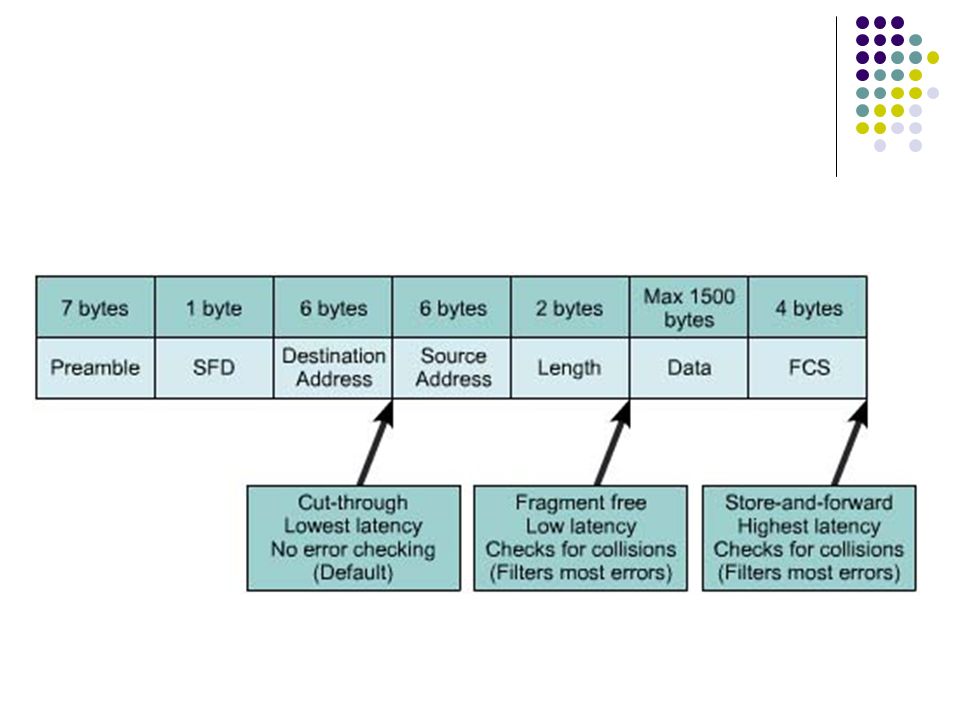
Switch modes How a frame is switched to the destination port is a trade off between latency and reliability. Cut-through A switch can start to transfer the frame as soon as the destination MAC address is received. No error checking. Lowest latency.

14
Store-and-forward The switch receives the entire frame before sending it out the destination port. To verify the Frame Check Sum (FCS). If the frame is invalid, it is discarded at the switch.. Fragment-free The switch reads the first 64 bytes (include frame header). This mode verifies the reliability of the addressing and Logical Link Control (LLC) protocol information to ensure the destination and handling of the data will be correct.
. If the frame is invalid, it is discarded at the switch.. Fragment-free The switch reads the first 64 bytes (include frame header). This mode verifies the reliability of the addressing and Logical Link Control (LLC) protocol information to ensure the destination and handling of the data will be correct..")
16
Spanning-Tree Protocol To prevent switch loops and broadcast storms. Usually caused by design errors or accident. Redundant paths -> to provide for reliability and fault tolerance Each switch in a LAN using STP sends special messages called Bridge Protocol Data Units (BPDUs) out all its ports to let other switches know of its existence and to elect a root bridge for the network.
 out all its ports to let other switches know of its existence and to elect a root bridge for the network..")
17
The switches then use the Spanning-Tree Algorithm (STA) to resolve and shut down the redundant paths. Each port on a switch using Spanning-Tree Protocol exists in one of the following five states:

18
Outline Ethernet Switching Collision Domains and Broadcast Domains

19
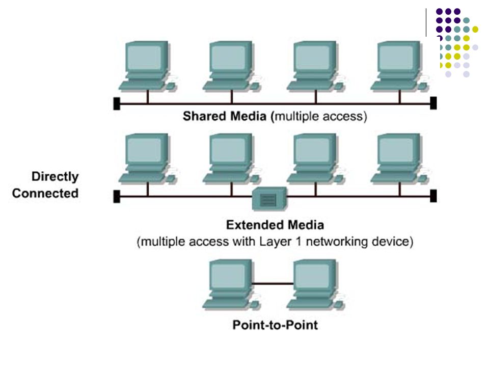
Shared media environments Layer 1 media and topologies : Shared media environment. Extended shared media environment. Accommodate for multiple access or longer cable distances. Point-to-point network environment Dialup network connections. Collisions only occur in a shared environment.

21
Collision domains Collisions cause the network to be inefficient. All transmission stops for a period of time. The length of this period of time without transmissions varies and is determined by a backoff algorithm for each network device. Layer 1 devices do not break up collision domains. Layer 2 and Layer 3 devices do break up collision domains. Breaking up, or increasing the number of collision domains with Layer 2 and 3 devices is also known as segmentation.

22
The 5-4-3-2-1 rule (repeater): 5 segments of network media 4 repeaters or hubs 3 host segments of the network 2 link sections (no hosts) 1 large collision domain
: 5 segments of network media 4 repeaters or hubs 3 host segments of the network 2 link sections (no hosts) 1 large collision domain")
23
Segmentation Layer 2 devices segment or divide collision domains. Keep tracking of the MAC addresses and which segment they are on. Layer 3 devices, like Layer 2 devices, do not forward collisions. Layer 3 devices and their functions will be covered in more depth in the section on broadcast domains.

25
Layer 2 broadcasts Destination MAC address 0xFFFFFFFFFFFF. Layer 2 devices must flood all broadcast and multicast traffic. Because the NIC must interrupt the CPU to process each broadcast or multicast group it belongs to (no discard), broadcast radiation affects the performance of hosts in the network. Workstations broadcast an Address Resolution Protocol (ARP) request every time they need to locate a MAC address that is not in the ARP table.
, broadcast radiation affects the performance of hosts in the network. Workstations broadcast an Address Resolution Protocol (ARP) request every time they need to locate a MAC address that is not in the ARP table..")
26
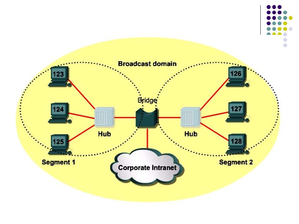
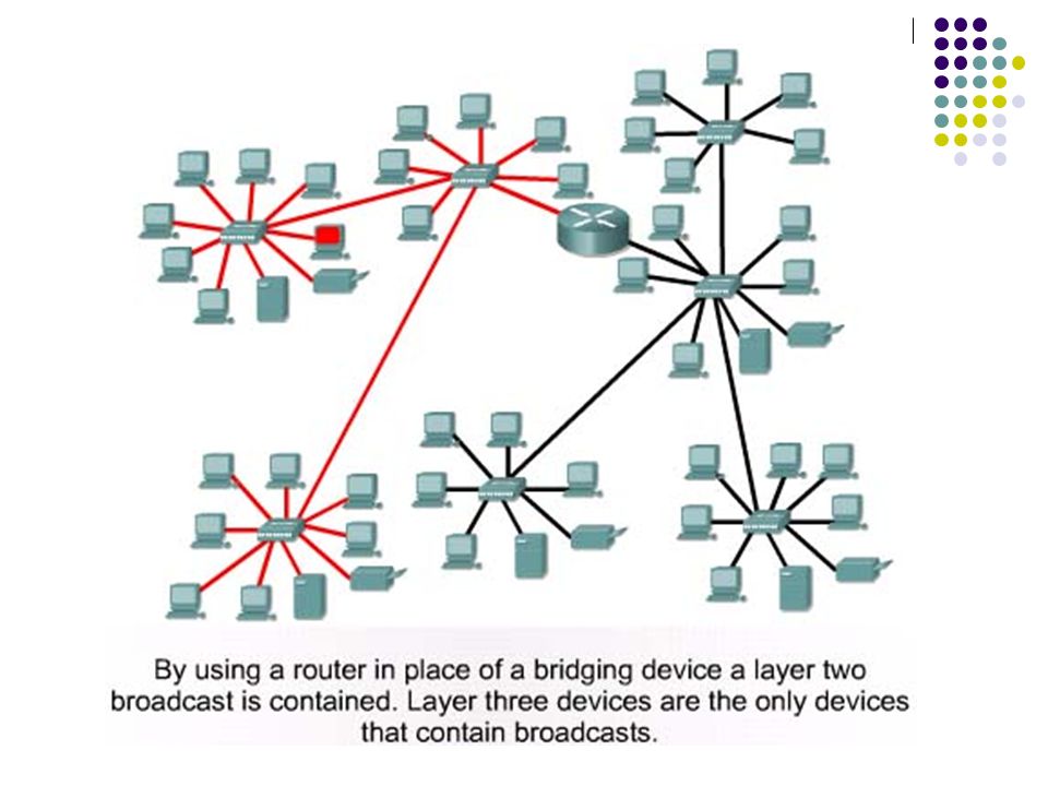
Broadcast domains Broadcasts are forwarded by Layer 2 devices. Broadcast domains are controlled at Layer 3 because routers do not forward broadcasts. Layer 3 forwarding is based on the destination IP address and not the MAC address. Use router to segment broadcast domains.

28
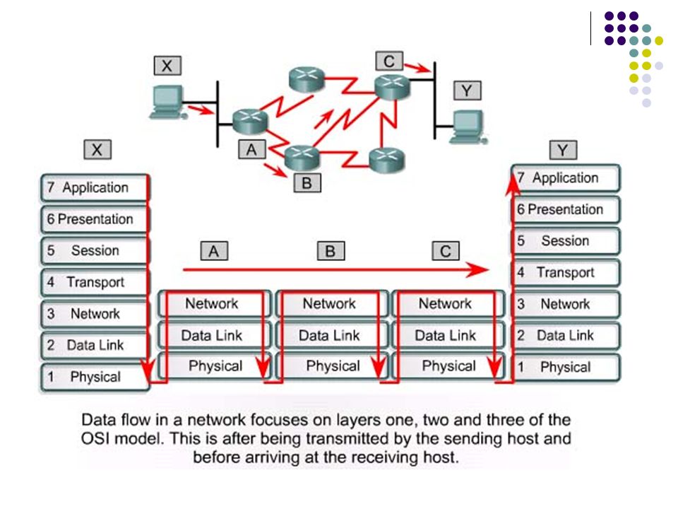
Introduction to data flow Layer 1 devices do no filtering, so everything that is received is passed on to the next segment. Layer 2 devices filter data frames based on the destination MAC address. Layer 3 devices filter data packets based on IP destination address. Data flow through a routed IP based network.

30
What is a network segment?

31
Good luck in your exams !

Similar presentations


 r Nodes connected to a hub, 100m max distance r Hub: physical.>")


 max distance between any two nodes without repeaters thin coaxial.>")
 address. Uses Application Specific Integrated Circuits.>")


