Download presentation
Presentation is loading. Please wait.

1
CS234/NetSys210: Advanced Topics in Networking Spring 2012 SIP and VoIP Kundan Singh, and Henning Schulzrinne "Peer-to-peer internet telephony using SIP" in NOSSDAV '05 Presentation by: Swaroop Kashyap Tiptur Srinivasa Anirudh Ramesh Iyer Tameem Anwar

2
Introduction to Session Initiation Protocol (SIP)
")
3
Introduction to SIP What is SIP ? Text-based protocol (Defined in RFC 3261) SIP Applications Network Elements – User Agent (UAC and UAS) – Proxy Server (UAC and UAS) – Registrar – Redirect Server – SBC
 SIP Applications Network Elements – User Agent (UAC and UAS) – Proxy Server (UAC and UAS) – Registrar – Redirect Server – SBC.")
4
SIP Messages Request messages –REGISTER –INVITE –ACK –CANCEL –BYE –OPTIONS

5
SIP Messages Response messages – PROVISIONAL (1XX) – SUCCESS (2XX) – REDIRECTION (3XX) – CLIENT ERROR (4XX) – SERVER ERROR (5XX) – GLOBAL FAILURES (6XX)
 – SUCCESS (2XX) – REDIRECTION (3XX) – CLIENT ERROR (4XX) – SERVER ERROR (5XX) – GLOBAL FAILURES (6XX)")
6
Assessment of VoIP quality over Internet backbones Athina P. Markopoulou, Fouad A. Tobagi, Mansour J. Karam Quality of service for VoIP traffic in Internet backbone was studied based on delay as the metric. 7 ISPs, 43 paths formed the test setup. A model is proposed to study and analyze VoIP traffic in Internet backbones based on characteristics of VoIP such as talkspurts and silence periods. This model is applied to the data trace obtained from the test setup (2.5 days worth of data). The study shows that certain backbone paths are not equipped to handle VoIP traffic. Examples of such paths are coast-to-coast paths which have high delay. The authors suggest that the primary reason for high delay in paths is due to the fact that there is no distinction between data and voice traffic. This prompts the authors to suggest IP QoS mechanism as a solution.
. The study shows that certain backbone paths are not equipped to handle VoIP traffic. Examples of such paths are coast-to-coast paths which have high delay. The authors suggest that the primary reason for high delay in paths is due to the fact that there is no distinction between data and voice traffic. This prompts the authors to suggest IP QoS mechanism as a solution..")
7
Improving VoIP Quality thorugh Path Switching Shu Tao, Kuai Xu, Antonio Estepa, Teng Fei,Lixin Gao,Roch Gu’erin, Jim Kurose, Don Towsley, Zhi-Li Zhang The effectiveness and benefits of path switching was examined, and its feasibility was demonstrated with the help of a of a prototype application- driven path switching gateway With sufficient path diversity, path switching is indeed capable of yielding meaningful improvements in voice quality The experiments also highlighted the benefit of adaptive decisions, especially in light of the often changing nature of the time scale at which network congestion takes place. The study suggests that by exploiting the inherent path diversity of the Internet, application-driven path switching is a viable option in providing quality-of-service to applications There is ongoing research being done to pursue these issues further in the context of hybrid wired/wireless networks and other applications such as video.

8
QoS-Enabled Voice support in the Next-Generation Internet: Issues, Existing Approaches and Challenges “Bo Li, Mounir Hamdi, Dongyi Jiang, and Xi-Ren Cao, Hong Kong University of Science, Technology,Y. Thomas Hou, Fujitsu Laboratories of America” There has been significant work done to establish the foundation to support VoIP. However, much remains to be done in order to ensure the QoS for VoIP and for multimedia traffic in general. This article surveys the existing technologies to support VoIP, in particular the basic mechanisms in the IETF Internet telephony architecture and ITU-T H.323-related recommendations. It then reviews the IETF QoS framework and major components in providing such QoS guarantees, including the Intserv and Diffserv models. In addition, this article also presents two leading companies (Cisco and Lucent) solutions to offering IP telephony services One another major issue currently under active development is internetworking with legacy net- works (i.e., PSTN). There are a number of proposals within the IEFT, in particular Media Gateway Control Protocol (MGCP).
 solutions to offering IP telephony services One another major issue currently under active development is internetworking with legacy net- works (i.e., PSTN). There are a number of proposals within the IEFT, in particular Media Gateway Control Protocol (MGCP)..")
9
Peer-to-peer internet telephony using SIP Kundan Singh, and Henning Schulzrinne, NOSSDAV '05

10
Peer-to-Peer Internet Telephony using SIP SIP using Client-Server model – Less Robustness and Scalability – Increased costs due to Maintenance and Configuration SIP using Peer-to-Peer model – Increased Robustness and Scalability – No maintenance and Configuration – Interoperability Tradeoff – Resource look-up – Security

11
Distributed Hash Table ( DHT) Types of Search Central Index (Napster) Distributed Index with flooding (Gnutella) Distributed Index with hashing (Chord) Basic Operations find(key),insert(key, value),delete (key), But no search
 Types of Search Central Index (Napster) Distributed Index with flooding (Gnutella) Distributed Index with hashing (Chord) Basic Operations find(key),insert(key, value),delete (key), But no search")
12
Background and Related work Chord – Ring based Distributed Hash Table for structured P2P systems – Identifier Circle – Keys assigned to successor – Evenly distributed keys and nodes – Finger table- O(log N) entries i th finger points to first node that succeeds n by at least 2 i-1 – Stabilization for join/leave – Iterative and Recursive Routing
 entries i th finger points to first node that succeeds n by at least 2 i-1 – Stabilization for join/leave – Iterative and Recursive Routing")
13
Background and Related work Skype – Based on Kazaa architecture – Open source P2P application for Internet telephony and instant messaging – Uses the concept of Super nodes. – Proprietary with Global Index server assigning Super nodes – Lookup similar to Kazaa using flooding unlike DHT-based lookup – Explicit server configurations not required

14
Background and Related work P2P with SIP – Recent work have concentrated on combining SIP and P2P – SIP combination with P2P done in two ways Replace SIP user registration and lookup by an existing P2P protocol Implementation a P2P algorithm using SIP messaging – The paper takes the second approach – No modification done to SIP messages – Advantages- Use of existing SIP components – Disadvantages- Transport message size overhead

15
Difference with File Sharing A single P2P-SIP node can handle many more requests than a file sharing node due to low data volume Caching of location information is not useful. The file sharing and directory lookup-based systems can tolerate high lookup latency. For file sharing applications, multiple almost exact copies of a popular file may be available. So node reliability does not matter.

16
Architecture Server Farm architecture P2P Overlay architecture Hybrid Super-Node architecture

17
Server Farm architecture Preserves Client-Server model DHT can used in a Server farm User registration done on only O(logN) servers Redundancy in servers can prove expensive
 servers Redundancy in servers can prove expensive")
18
Client Overlay architecture Pure P2P overlay with all clients acting as a server No server maintenance and configuration needed Problem- Equal capacity and availability Example- Client behind firewall or NAT

19
/watch?v=1pKztSTmeIc Super Node architecture Hybrid design (Similar to Kazaa) Selection of Super nodes – High capacity (Bandwidth, CPU, memory) – Availability (up time, public IP address) – Transition from a regular node to Super node (Local decision)
 Selection of Super nodes – High capacity (Bandwidth, CPU, memory) – Availability (up time, public IP address) – Transition from a regular node to Super node (Local decision)")
20
P2P-SIP node block diagram Discover->User Interface->DHT(Chord)
")
21
Design and Implementation Naming Authentication SIP messages DHT discovery and join SIP message routing Reliability Adaptor for existing SIP phones

22
Naming Representation of end points using SIP URI's – Eg-: sip:17@192.1.2.3:8054 17 is the key returned by Chord's hash function Domain representation encouraged – sip:10@example.com SIP user identifiers (UI) randomly assigned Authentication ?
 randomly assigned Authentication")
23
Validity of UI done when an user signs up to the P2P-SIP network Absence of Public Key Infrastructure ? Password obtained used in REGISTER authentication Time-to-Live value used to determine user existence Authentication

24
SIP REGISTER- Used for registration and DHT maintenance SIP REGISTER used in query and update mode Query mode- User is asking for Contact information of the node identifier given in TO header Update mode- Contact information present in message Mostly done to update bindings given in TO header SIP messages

25
SIP REGISTER message used, Request-URI could be sip:224.0.1.75 TO header identifies and discovers other P2P- SIP peers in the network Once the node is discovered, SIP REGISTER is used to join the DHT Chord Stabilization ? (Hint: Registration of end points) DHT Discovery and Join
 DHT Discovery and Join.")
26
Every node owns the responsibility for its subset of the key space Destination key is determined from TO header If Destination key belongs to same key space of the received node, then node is the registrar Redirect or the proxy server is used to determine the locations available for the destination user. Otherwise, request is proxied to the next hop node based on Chord algorithm and its inherent data structures SIP message routing

27
Each Chord node stores log(N) successor addresses User registrations replicated at K successive nodes Users unregistered when exit is graceful Registrar Node malicious ? Reliability

28
Advanced Services Apart from user registration and call routing, which are the core services of SIP, P2P-SIP also offers some advanced services. These services are based on SIP URIs. Example- sip:staff- meet@office.com or dialog.voicexml@ivr.net The services are: Offline messages Multi-party conferencing NAT and firewall traversal Directory Service

29
Advanced Services – Offline Messaging Offline messages – Caller calls callee and callee is unavailable then a message is left by caller to callee. Needs storage and signaling. Current P2P file storage + IP telephony cannot handle this as we also need message waiting indication. The P2P-SIP client running on the destination user’s machine can store the message if the destination user did not pick up the phone. The problem comes when the destination phone itself is not active or the user has not started her client. The message waiting signal is implemented using POST (POST is a cooperative, decentralized messaging system that supports traditional services like email, news, IM) which is built on a P2P overlay. To receive the offline message, the destination node subscribes to the message waiting indication (MWI) event with the P2P network and gets notified on startup when a new offline message is available.
 which is built on a P2P overlay. To receive the offline message, the destination node subscribes to the message waiting indication (MWI) event with the P2P network and gets notified on startup when a new offline message is available..")
30
Advanced Services – Offline Messaging Contd There are three places where we can store the offline messages: the source, the destination or some intermediate node in the P2P overlay. When Alice calls Bob and Bob is not online, the message should be stored reliably by the system and delivered to Bob when he comes online. Then a possible solution is to use the DHT peer responsible for storing Bob' location also store his offline messages. In case of storage node failure message is replicated and kept consistent using Oceanstore architecture (a well-known architecture for global-scale persistent storage).
..")
31
Advanced Services – Offline Messaging Contd Alternate model is to store the message at the sender-end itself. If the message is not delivered or the storage node fails, then the caller node finds the new storage node and records the message again without any user intervention. On boot-up a node checks for any undelivered message from past boot cycle, and tries to re-send them upon bandwidth and CPU availability. This model has a security flaw – What if the sender-end is an Internet kiosk? To overcome this problem – A third-party storage server can take the ownership of sending the message and store the message.

32
Advanced Services – Multi-party Conferencing There are 3 methods to do a multi-party conference using P2P-SIP, A participating member can become mixer for small scale ad-hoc conferencing. Completely decentralized approach can be taken to exchange member information and full-mesh signaling is established. Multicast media distribution tree model can be used if number of senders are less at any point of time. In all these models there is a trade-off in terms of reliability (single point of failure in case of single mixer), complexity and bandwidth utilization.
, complexity and bandwidth utilization..")
33
Advanced Services – NAT and Firewall Traversal In an ideal world, ISPs and corporate system administrators should enable their NAT and firewall devices with SIP proxies or application level gateways. There are two aspects to overcoming the problem posed by ISPs: Automatic detection of the type of NAT and firewall. Detection is done at the application startup when the node connects to a super-node. Tunneling through the NAT and firewall devices for inbound or outbound messages. The node implements the Interactive Connectivity Establishment (ICE) algorithm for NAT traversal (Can use both TCP and UDP). Also every node has a built-in STUN (Simple Traversal of UDP through NAT) and TURN (Traversal Using Relay NAT) server.
 algorithm for NAT traversal (Can use both TCP and UDP). Also every node has a built-in STUN (Simple Traversal of UDP through NAT) and TURN (Traversal Using Relay NAT) server..")
34
Advanced Services – Directory Service In any chat application people tend to search by first-name or last-name. Usually only partial names are supplied, which leads to wildcard character behaviour. Queries could also be with respect to number of hops from the person issuing the query. General DHT does not support these type of queries. These queries are supported by, Registering combination of first-name and last-name in DHT. Doing a blind search in acquaintances graph based on small number of hops-to-live.

35
Performance prediction - Scalability Scalability With N super-nodes and n nodes in the chord system, number of keys k per node = n/N. REGISTER refresh rate is rs, refresh rate for finger table entry is rf. Call arrival (Possion distribution) with mean c, user registration (Uniform distribution) with mean t per user, Node churn (Possion distribution) with mean λ. Average lookup time in Chord is O(log N), as there are O(log N) finger table entries Node join & leave messages generated is O( (log N)^2) The average message rate per node is sum of the message rates due to refresh, call arrival, user registration and node join or leave If each node can handle C requests per second, then the equation C = M gives the maximum possible number of nodes, Nmax, in the system, which roughly translates to Nmax = 2^(C/(r+c)) for large N, where r is the refresh rate and c is the call rate. Example: If a node supports 10 requests per second, r=1min, c=1per min, then max nodes in system = 2^(10*30).
 with mean c, user registration (Uniform distribution) with mean t per user, Node churn (Possion distribution) with mean λ. Average lookup time in Chord is O(log N), as there are O(log N) finger table entries Node join & leave messages generated is O( (log N)^2) The average message rate per node is sum of the message rates due to refresh, call arrival, user registration and node join or leave If each node can handle C requests per second, then the equation C = M gives the maximum possible number of nodes, Nmax, in the system, which roughly translates to Nmax = 2^(C/(r+c)) for large N, where r is the refresh rate and c is the call rate. Example: If a node supports 10 requests per second, r=1min, c=1per min, then max nodes in system = 2^(10*30)..")
36
Performance prediction - Reliability Reliability What happens when a node fails? Impacted entity is user registration records/data in that node. Reliability is achieved by, Refresh rate is increased so that node failure detection happens quickly. User registration refresh rate is increased so that loss is very brief. User registration record is replicated at multiple nodes at log(N) successive nodes.
 successive nodes..")
37
Performance prediction – Call setup latency Latency O(log N) nodes to be looked-up before a call can be setup. This is a bottleneck in reducing call setup latency. In a 10000 node cluster it takes 6 hops ~ 1-2 seconds before call is made. This is higher than vanilla SIP (200ms) but can be tolerated as phones ring for a much higher time than 1-2 seconds. P2P synchronization latency due to churn in nodes/records can result in multiple retransmissions before call setup is complete. Example skype takes 3-8 seconds. To solve this issue a hybrid model of structured & unstructured P2P network is needed with one hop lookup. This solution assumes large storage space is available in peers.
 but can be tolerated as phones ring for a much higher time than 1-2 seconds. P2P synchronization latency due to churn in nodes/records can result in multiple retransmissions before call setup is complete. Example skype takes 3-8 seconds. To solve this issue a hybrid model of structured & unstructured P2P network is needed with one hop lookup. This solution assumes large storage space is available in peers..")
38
Open Issues Security, trust and reward Security threats – Trust, Malicious behaviour by nodes, DoS Trust – Proprietary protocols like Skype has built-in trust among peers but open protocols like P2P-SIP may have malicious clients. Reward – As in any P2P “Reward nodes serving in DHT, punish free-riders”. Media routing In case of media transfer paths we need media relay node in NAT and firewall scenarios. Stability of relay node is important as delay due to relay node dropping out is not tolerable.

39
Thank You !

40
Detailed slides of QoS papers

41
CS234/NetSys210: Advanced Topics in Networking Spring 2012 Assessment of VoIP quality over Internet backbones “Athina P. Markopoulou, Fouad A. Tobagi, Mansour J. Karam” Presentation by: Swaroop Kashyap Tiptur Srinivasa Anirudh Ramesh Iyer Tameem Anwar

42
Introduction to Voice over IP (VoIP)
")
43
Introduction to VoIP What is VoIP ? VoIP Protocols MGCP:Media Gateway Control Protocol RVP over IP:Remote Voice Protocol Over IP Specification SGCP:Simple Gateway Control Protocol SIP:Session Initiation Protocol Skinny:Skinny Client Control Protocol (SCCP)
.")
44
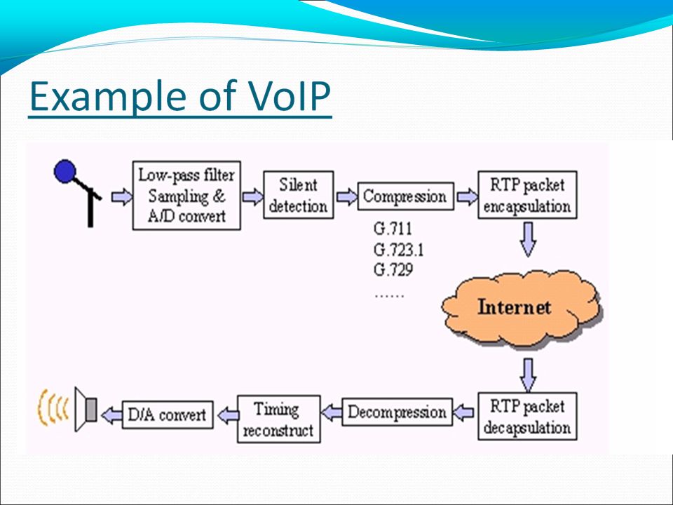
VoIP Architecture Coding & Decoding of Analog Voice Analog-to-Digital and Digital-to-Analog conversions Compression Signaling Call setup & tear down Resource & coding negotiation Transport of Bearer Traffic Voice packet transmission Routing Support of quality of service Numbering Phone number, IP address

45
VoIP Architecture - Contd A naive representation of VoIP system as shown in this paper Sender Encoder: Does sampling and creates a constant bit rate stream Packetizer: encapsulates speech samples into packets of equal sizes Receiver Playback buffer: An important component which absorbs delay/jitter De-packetizer & Decoder: Reconstruct the speech signal

46
VoIP Architecture - Contd Codecs: They are used to convert an analog voice signal to digitally encoded version and vice-versa. Codecs vary in the sound quality, bandwidth required, computational requirements, etc. Each service, program, phone, gateway, etc typically supports several different codecs, and when talking to each other, negotiate which codec they will use.

47
Assessment of VoIP Goal of the paper: Assessment of VoIP over today' Internet Organization of the paper Section I & II describes the components of VoIP system under evaluation → Already Covered in Architecture Section III presents the quality measures used for assessing the impairments over the network and our methodology for rating a call Section IV describes the probe measurements and classify the traces into categories according to their delay and loss characteristics Section V application of proposed methodology to the traces & discuss numerical results pertaining to phone calls quality Section VI concludes the paper

48
Assessment of VoIP – Quality Metrics Delay and Loss Mean Opinion Score (MOS) It is a numerical method of expressing voice and video quality MOS is quite subjective, as it is based figures that result from what is perceived by people during tests MOS is expressed in one number, from 1 to 5, 1 being the worst and 5 the best Emodel It is a computational model, standardized by ITU-T, that uses transmission parameters to predict the subjective quality of packetized voice
 It is a numerical method of expressing voice and video quality MOS is quite subjective, as it is based figures that result from what is perceived by people during tests MOS is expressed in one number, from 1 to 5, 1 being the worst and 5 the best Emodel It is a computational model, standardized by ITU-T, that uses transmission parameters to predict the subjective quality of packetized voice")
49
Assessment of VoIP – Quality Metrics Contd How do we obtain a subjective score (MOS) from metrics like delay, jitter, loss? Emodel provides a solution to this problem by defining a computation model (based on statistical analysis) First we calcluate R rating of a call using the formula, R = (Ro − Is) − Id − Ie + A, where Ro (effect of noise) and Is (accounting for loud connection and quantization) terms are intrinsic to the voice signal. Id and Ie capture the effect of delay and signal distortion respectively. More about Id and Ie in next slide.
 First we calcluate R rating of a call using the formula, R = (Ro − Is) − Id − Ie + A, where Ro (effect of noise) and Is (accounting for loud connection and quantization) terms are intrinsic to the voice signal. Id and Ie capture the effect of delay and signal distortion respectively. More about Id and Ie in next slide..")
50
Assessment of VoIP – Quality Metrics Contd Delay impairment factor Id, models the quality degradation due to one- way or “mouth-to-ear”(m2e) delay. Id = Idte(m2e,EL2) + Idle(m2e,EL1) + Idd(m2e), where terms Idte(m2e,EL2) and Idle(m2e,EL1) capture the impairments due to talker and listener echo respectively. EL = ∞ (infinite echo loss) corresponds to perfect echo cancellation. Term Idd(m2e) captures the interactivity impairment when the m2e delay is large, even with perfect echo cancellation. Along-with this definition a new parameter “task” is defined to measure interactive nature of call (eg: business conference – which consists of continuous bursts by different people OR normal Bob-Alice conversation). 1 is defined to be highly interactive (random and bursty), 6 is defined to be relaxed and free conversation.
 + Idle(m2e,EL1) + Idd(m2e), where terms Idte(m2e,EL2) and Idle(m2e,EL1) capture the impairments due to talker and listener echo respectively. EL = ∞ (infinite echo loss) corresponds to perfect echo cancellation. Term Idd(m2e) captures the interactivity impairment when the m2e delay is large, even with perfect echo cancellation. Along-with this definition a new parameter task is defined to measure interactive nature of call (eg: business conference – which consists of continuous bursts by different people OR normal Bob-Alice conversation). 1 is defined to be highly interactive (random and bursty), 6 is defined to be relaxed and free conversation..")
51
Assessment of VoIP – Quality Metrics Contd Loss impairment Ie captures the distortion of the original voice signal due to low-rate codec, and packet loss in both the network and the playback buffer. Table shows effect of Codec on this parameter.

52
Assessment of VoIP – Quality Metrics Contd Observed facts about Ie and Id in different calls (more about test setup in actual methodology and results slides)
")
53
Assessment of VoIP – Quality Metrics Contd Finally, now that we have R rating by evaluation Ie and Id we can get MOS by using the translation shown below. (Needed because PSTN call quality is measured in MOS and is >3.6)
.")
54
Assessment of VoIP – Quality Metrics Contd An important factor/issue while measuring the parameters that we have ssen so far is the issue of using correct time interval to measure these parameters. For long duration calls a natural approach is to divide the call duration into fixed time intervals and assess the quality of each interval independently. Evaluating each interval in terms of Ie leads to transitions between plateaus of quality. (Also accounts human memory about bad/good transitions by using distribution for forgetting time interval when calculating instantaneous MOS. Bad transition is high loss aka “bursts” and Good transition is low loss aka “gaps”)
.")
55
Assessment of VoIP – Internet Measurements A model with adaptive playback delay is used in measurement to simulate real-VoIP implementations and experiment is conducted to measure the parameters involved in “Call Quality”. Probes are configured across 7 different Service Providers in 5 major cities to measure the parameters for a duration of 2.5 days. A probe packet (based on codec scheme and adaptive playback delay) consists of 50 Bytes of data sent every 10ms. [50Bytes = 10Bytes of data + 40Bytes of RTP/TCP/IP headers). This corresponds to G.729 rate of 8Kbps A total of 43 paths are tested to assess their support for VoIP and create a model/rules to ensure Internet backbone can support toll-quality VoIP.
 consists of 50 Bytes of data sent every 10ms. [50Bytes = 10Bytes of data + 40Bytes of RTP/TCP/IP headers). This corresponds to G.729 rate of 8Kbps A total of 43 paths are tested to assess their support for VoIP and create a model/rules to ensure Internet backbone can support toll-quality VoIP..")
56
Assessment of VoIP – Internet Measurements The following facts could be observed from the probe/trace data The paths could be classified into different types (A,B, C, D, E). Paths of type A and B connect ASH, EWR and AND on the east coast and have low propagation delays, i.e. below 10ms. Paths of type C, D on E on the other hand, connect cities across the US. Based on the variable component of delay, paths of type A and C have practically no queuing. Paths of type B and D have in general low queuing, except for clustered delay spikes. Paths of type E are coast-to-coast loaded paths. The queuing component is high and the delay varies slowly in a short time scale.

57
Assessment of VoIP – Internet Measurements Only 3 out of the 43 paths had consistently no loss during the 2.5 days observed. The rest of them incurred loss durations that varied from 10ms up to 33.72sec, although the average loss rateswere low (e.g. <0.2%). 6 out of 7 providers experienced outage periods 10-220sec for 1-2 times per day. These occurred due to convergence delay following route change. 0.5-2sec loss durations were correlated with delay spikes. The number of out-of-order packets was negligible.
. 6 out of 7 providers experienced outage periods sec for 1-2 times per day. These occurred due to convergence delay following route change sec loss durations were correlated with delay spikes. The number of out-of-order packets was negligible..")
58
Assessment of VoIP – Results So far we have covered “Call Quality Metrics”, “Model to assess quality” and “Trace data obtained from probes” To tie it all together “Model” obtained from Call Quality Metrics is applied to “Trace data” to validate the model and understand parameters that drive VoIP quality

59
Assessment of VoIP – Results Evaluating the trace data using an example: a 15 minute call on path of type E, it can be seen that a fixed playout of 100ms ensures that Ie is low and optimal region is ~ 200ms for fixed playout (MOS = 4). Even adaptive model has a playout close to it (122ms) with max MOS = 3.6
 with max MOS = 3.6.")
60
Assessment of VoIP – Results Contd For the trace example in previous slide, the loss-delay tradeoff graph with variation in type of “task” and echo-loss looks like,

61
Assessment of VoIP – Results Contd Looking at instantaneous quality of calls initiated at random times spread over an hour, it can be seen that 150ms playback delay is optimal choice as only 6% have final MOS <3.6 100ms playback results in high percentage of calls in low MOS region. Adaptive playback delay shows linear nature

62
Assessment of VoIP – Results Contd Looking at instantaneous quality of calls initiated at random times spread over an entire day, it can be seen that 150ms playback delay is optimal choice as only 6% have final MOS <3.6 100ms playback results in high percentage of calls in low MOS region. And adaptive playback delay shows no particular performance benefit with 10% of calls having MOS < 3.5

63
Assessment of VoIP – Results Contd The previous graphs/results were based on time duration on same path. Impact of different types of paths are, Paths of type A and B have low delay and low delay variability. A fixed playback delay of 100ms is sufficient for MOS > 4 Paths of type B and D exhibit periodically clusters of high spikes. Performance is low in both fixed & adaptive delays. Only a very high fixed delay results in 10% of calls with MOS < 3.5

64
Assessment of VoIP – Results Contd Combining inferences drawn for different times and paths the following results are obtained, Some ISP backbones (i.e. those that are over-provisioned and have low delay variability, namely types A and C) are indeed able to provide high quality VoIP today. This is true for both short and long distance paths. Highly loaded paths (type E) as well as some over-provisioned paths exhibiting frequent delay spikes (types B and D) have poor VoIP performance. Under the best scenarios these paths are barely able to provide acceptable (MOS > 3.6) VoIP service. The poor VoIP performance on loaded backbones (type E) makes a strong case for separating voice and giving it priority. It also needs a more sophisticated handling than over-provisioning. There exists a tradeoff between delay and buffer loss. Maximum MOS is more sensitive to an increase in loss rather than to an increase in delay. The reason for this is that the underlying Ie curves are sharper than the Id curves.
 are indeed able to provide high quality VoIP today. This is true for both short and long distance paths. Highly loaded paths (type E) as well as some over-provisioned paths exhibiting frequent delay spikes (types B and D) have poor VoIP performance. Under the best scenarios these paths are barely able to provide acceptable (MOS > 3.6) VoIP service. The poor VoIP performance on loaded backbones (type E) makes a strong case for separating voice and giving it priority. It also needs a more sophisticated handling than over-provisioning. There exists a tradeoff between delay and buffer loss. Maximum MOS is more sensitive to an increase in loss rather than to an increase in delay. The reason for this is that the underlying Ie curves are sharper than the Id curves..")
65
Assessment of VoIP – Results Contd Combining inferences drawn for different times and paths the following results are obtained, The need for adaptive playout comes when EITHER the delay is high and there is no margin for overestimating it OR, when the delay is unknown and the receiver does not know how to select an appropriate fixed value. Tuning of parameters such as thresholds for spike detection, weights used for moving averages cannot be realistically optimized (proven with observations). Delay estimation mechanism has weakness of using TCP-like prediction (p = d+4v) which tends to over-estimate delays beyond what is appropriate to preserve interactivity. Also adapting at the beginning of talkspurts fails to react to short lived spikes while it still unnecessarily leads to high delays.
. Delay estimation mechanism has weakness of using TCP-like prediction (p = d+4v) which tends to over-estimate delays beyond what is appropriate to preserve interactivity. Also adapting at the beginning of talkspurts fails to react to short lived spikes while it still unnecessarily leads to high delays..")
66
Assessment of VoIP – Conclusion After seeing the results and considering, Delay and loss Voice quality Playback buffer schemes Conclusion: Many paths performed poorly for VoIP traffic due to long delays and large delay variability Playback buffer schemes – tradeoff between data loss and increased delay in the buffer Overall rated VoIP as poor Mark voice traffic and give it preferential treatment Choose playback buffer scheme to match delay pattern

67
Questions?

68
Presentation by: Swaroop Kashyap Tiptur Srinivasa Anirudh Ramesh Iyer Tameem Anwar CS234/NetSys210: Advanced Topics in Networking Spring 2012 Improving VoIP Quality thorugh Path Switching Shu Tao, Kuai Xu, Antonio Estepa, Teng Fei,Lixin Gao,Roch Gu’erin, Jim Kurose, Don Towsley, Zhi-Li Zhang

69
Introduction i)VoIP ii) Factors affecting VoIP Quality Architecture of Path Switching System How Path Quality is Estimated Issues about Path Switching Performance Evaluation
VoIP ii) Factors affecting VoIP Quality Architecture of Path Switching System How Path Quality is Estimated Issues about Path Switching Performance Evaluation")
71
VoIP requires minimum service guarantees that go beyond the best-effort structure of today’s IP networks

72
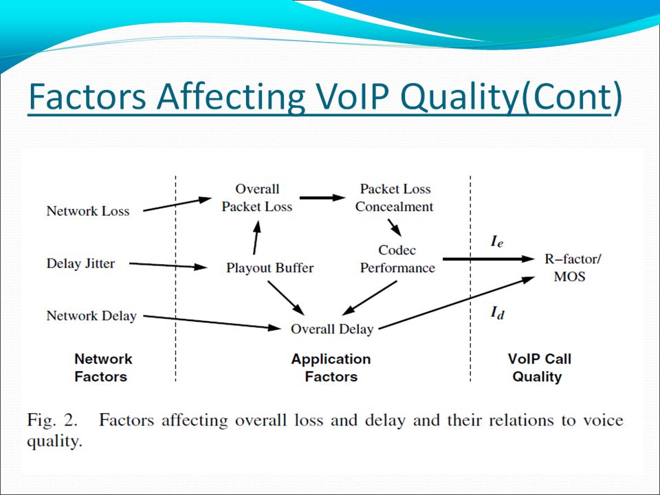
1) Network Factors Packet Loss Delay Jitter Network Delay 2) Application Factors Playout Buffers Codec Performance
 Network Factors Packet Loss Delay Jitter Network Delay 2) Application Factors Playout Buffers Codec Performance")
75
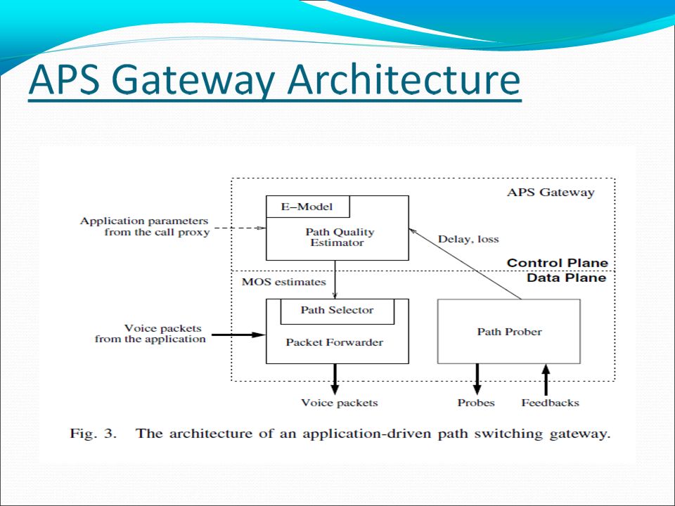
APS Gateway Components Path Prober Send UDP probes, which are generated to emulate the behavior of a VoIP call, on each available path periodically Receive feedbacks containing the delay and loss statistics. Path Quality Estimator Translate network path measurements into application quality estimates using the E-model

76
APS Gateway Components (Cont) Path Selector Dynamically decide the best performing path for each voice call Packet Forwarder Integrated with the path selector Forward the voice packet along the corresponding path.
 Path Selector Dynamically decide the best performing path for each voice call Packet Forwarder Integrated with the path selector Forward the voice packet along the corresponding path.")
77
Perceived voice quality is typically measured by the Mean Opinion Score (MOS), a subjective quality score that ranges from 1 ( unacceptable) to 5 (excellent). The MOS method is from “ Methods for subjective determination of transmission quality”, ITU-T Recommendation P.800, August 1996.

79
The ITU-T E-Model defines a R-factor,that ranges from 0 to 100,combines different aspects of voice quality impairments : The E-Model method is from “ The E-Model, a computational model for use in transition planning”, ITU-T Recommendation G.107, March 2003

80
Among all of the factors in Equation 1,only Id and Ie are typically considered variable in a VoIP System. Using default values for all other factors reduces the model to R = 94.2 – Ie - Id When R=94.2, the value of MOS is 4.4

81
Ie accounts for impairment caused by both encoding and transmission losses

82
Id accounts for impairment caused by network delay, codec-related delay and play out buffering delay.

84
Path Quality Prediction Estimating the Benefits of Path Switching Time- Scale Adaptive Path Switching Algorithm

87
A typical example that shows how path switching avoids quality degradations: (a) quality variations on the two paths (top), and (b) the resulting quality when path switching is applied (bottom).
 quality variations on the two paths (top), and (b) the resulting quality when path switching is applied (bottom).")
88
Conclusion The effectiveness and benefits of path switching was examined, and its feasibility was demonstrated with the help of a of a prototype application-driven path switching gateway With sufficient path diversity, path switching is indeed capable of yielding meaningful improvements in voice quality The experiments also highlighted the benefit of adaptive decisions, especially in light of the often changing nature of the time scale at which network congestion takes place.

89
The study suggests that by exploiting the inherent path diversity of the Internet, application-driven path switching is a viable option in providing quality-of- service to applications Intelligently creating and exploiting path diversity via mechanisms such as overlays and dynamic path switching is therefore an important avenue to meet and improve the quality-of-service of applications There is ongoing research being done to pursue these issues further in the context of hybrid wired/wireless networks and other applications such as video.

90
The APS gateways

92
QoS-Enabled Voice support in the Next-Generation Internet: Issues, Existing Approaches and Challenges “Bo Li, Mounir Hamdi, Dongyi Jiang, and Xi-Ren Cao, Hong Kong University of Science, Technology,Y. Thomas Hou, Fujitsu Laboratories of America” Presentation by: Swaroop Kashyap Tiptur Srinivasa Anirudh Ramesh Iyer Tameem Anwar CS234/NetSys210: Advanced Topics in Networking Spring 2012

93
Introduction While the Internet has served as a research and education vehicle for more than two decades, the last few years have witnessed its tremendous growth and its great potential for providing a wide variety of services Over the past few years, reliability and quality have quickly improved, and Internet telephony is now one of the fastest growing industries. The reason behind Internet telephony’s success is that it can potentially bring enormous benefits to end users, telecommunication companies, and carriers.

94
Advantages of IP Telephony It is cheaper for end users to make an Inter- net telephony call than a circuit-switched call, mainly because operators can avoid paying interconnect charges. Internet telephony gives new operators an easy and cost- efficient way to compete with incumbent operators Engineering economics favors Internet telephony. While a circuit-switched telephony call takes up to 64 kb/s, an Internet telephony call only takes up to 6–8 kb/s and possibly even less bandwidth.

95
In the longer term, it offers exciting new value-added opportunities such as high fidelity stereo conferencing bridges, Internet multicast conferencing, and telephony distance learning applications, phone directories and screen popping via IP, or even “voice Web browsing.” Internet telephony gives carriers the ability to manage a single network handling both voice and data. Internet telephony will also create end user opportunities and demand for new services. Advantages of IP Telephony(Cont.)
.")
96
Latency has been constantly undergoing changes and will continue to improve, driven by three factors: Improved gateways (developers are just beginning to squeeze latency out of the first generation of products) Deployment over private networks — by deploying gateways on private circuits, organizations Service providers can control the bandwidth utilization and hence latency Latency
 Deployment over private networks — by deploying gateways on private circuits, organizations Service providers can control the bandwidth utilization and hence latency Latency")
97
Objective The objective of this article is to review the recent developments and key enabling technologies in providing QoS supporting for voice communications in the next- generation Internet. The rest of the article is organized as follows. We first review the existing technologies in supporting VoIP networks, especially the basic mechanisms in the IETF Internet telephony architecture.

98
Internet Telephony Standards To support Internet telephony and other related applications, standards are being recommended and developed to insure interoperability ITU H.323 specification for Internet telephony is gaining widespread acceptance among software vendors The IETF is developing protocols such as Session Initiation Protocol (SIP) for multimedia session initiation, and RTSP for controlling multimedia servers on the Internet that can work together with H.323.
 for multimedia session initiation, and RTSP for controlling multimedia servers on the Internet that can work together with H.323.")
99
Internet Telephony Standards(cont) Real-Time Transport Protocol (RTP) is interwoven with all the above protocols. It is used by H.323 terminals as the transport protocol for multimedia; both SIP and RTSP were designed to control multimedia sessions delivered over RTP. To this end, it guarantees that each participant in a session has a unique identifier, providing applications a way to de- multiplex packets from different users. RTP also contains a control component, called the Real-Time Control Protocol (RTCP). It is multicast to the same multicast group as RTP, but on a different port number.
. It is multicast to the same multicast group as RTP, but on a different port number..")
100
One of the key components supporting VoIP is a signaling protocol, which has to provide the following functions: User location Session establishment Session negotiation Call participant management Feature invocation Within the IETF, two protocols are defined to implement these tasks: Session Initiation Protocol(SIP) and Session Description Protocol (SDP) Internet Telephony Standards(cont)
 and Session Description Protocol (SDP) Internet Telephony Standards(cont)")
101
Session Initiation Protocol SIP is used to initiate a session between users. It provides user location services, call establishment, call participant management, and limited feature invocation. SIP is a client- server protocol. This means that requests are generated by one entity (client), and sent to a receiving entity (the server), which process them. There are three types of servers. SIP requests can traverse many proxy servers, each of which receives a request and forwards to the next- hop server, which may be another proxy server or the final user agency server. A server may also act as a redirect server, informing the client of the next-hop server so that the client can contact it directly.
, and sent to a receiving entity (the server), which process them. There are three types of servers. SIP requests can traverse many proxy servers, each of which receives a request and forwards to the next- hop server, which may be another proxy server or the final user agency server. A server may also act as a redirect server, informing the client of the next-hop server so that the client can contact it directly..")
102
Session Description Protocol SDP is used to describe multimedia sessions for both telephony and distributed applications. The protocol includes several kinds of information, as follows Media streams convey the type for each media stream. For each media stream, the destination address (unicast or multicast ) is indicated by Address. Ports define the UDP port numbers for each sending or/and receiving stream. Payload type conveys the media formats that can be used during the session. For a broadcast-style session such as a television program, start and stop times convey the start, stop, and repeat times of the session Originator names the originator of the session and how that person can be contacted.
 is indicated by Address. Ports define the UDP port numbers for each sending or/and receiving stream. Payload type conveys the media formats that can be used during the session. For a broadcast-style session such as a television program, start and stop times convey the start, stop, and repeat times of the session Originator names the originator of the session and how that person can be contacted..")
103
Basic Mechanisms in H.323 H.323 are a series of Recommendations of the ITU-T to enable multimedia communications in packet switched networks H.323 is designed to extend the traditionally circuit-based services including audiovisual and multimedia conferencing services into packet-based networks One of the primary objectives of H.323 is the interoperability with the existing circuit-switching systems (PSTN and ISDN). The basic elements defined in H.323 architecture are: terminals, gateways, gatekeepers, and multipoint control units (MCUs), in which the terminals, gateways, and MCUs are collectively referred as endpoints.
, in which the terminals, gateways, and MCUs are collectively referred as endpoints..")
104
The H.323 Protocol Stack

105
A gateway, as the name suggests, is an intermediate device to provide interoperation between H.323 compliant devices and non-H.323 devices, in particular PSTN and ISDN devices. A gatekeeper manages a set of registered endpoints, collectively referred as a zone. Its main functions include call admission (or call authorization), address resolution, and other management-related functions. An MCU provides the necessary control needed for multiparty video conferences. It contains two logical components: a multipoint controller (MC) for call control coordination and a multipoint processor (MP) to handle audio or video mixing. Basic Mechanisms in H.323(cont)
, address resolution, and other management-related functions. An MCU provides the necessary control needed for multiparty video conferences. It contains two logical components: a multipoint controller (MC) for call control coordination and a multipoint processor (MP) to handle audio or video mixing. Basic Mechanisms in H.323(cont).")
106
H.323 Protocol Phases

107
The IETF Differentiated Services Framework The Diffserv architecture is based on a simple model where traffic entering a network is classified and possibly conditioned at the boundaries of the network, and assigned to different behavior aggregates (BAs), with each BA being identified by a single Diffserv code- point (DSCP) Sophisticated classification, marking, policing, and shaping operations need only be implemented at network boundaries or hosts. A Diffserv architecture can be specified by defining or implementing the following four components: The services provided to a traffic aggregate The traffic conditioning functions and PHBs used to realize the services The Diffserv field value (DSCP) used to mark packets to select a PHB The particular node mechanism to realize a PHB.
 used to mark packets to select a PHB The particular node mechanism to realize a PHB..")
108
There are two approaches to provide Diffserv: The first approach specifies the QoS in deterministically or statistically quantitative terms of throughput, delay, jitter, and/or loss. Such approach is called quantitative Diffserv. The second approach specifies the services in terms of some relative priority of access to network resources and is called priority based Diffserv.

109
The CISCO Solution: Enterprise IP Telephony The Cisco solution for IP telephony in enterprise networks includes hardware, such as switches, routers, IP/PSTN gateways, desktop IP phones, and software, such as the call manager By using routers and gateways to connect the PBX, voice traffic can be carried over data IP networks. Call management soft- ware and IP telephones are deployed in the existing IP networks at each remote site. This will reduce the cost of WAN consolidation while at the same time eliminating the cost of installing a second network at each remote location. Packet classification identifies and cate- gorizes network traffic into multiple classes. The Cisco IP phone can set the IPv4 ToS at the ingress to the network.

110
The QoS guarantees are primarily provided by two mechanisms: The call manager equipped with a resource reservation protocol (e.g., RSVP) A priority queue mechanism. The priority queue mechanism is maintained in the core routers, and is responsible for high-speed switching and transport as well as congestion avoidance. The CISCO Solution: Enterprise IP Telephony

111
The Cisco Data and IP telephony configuration

112
Lucent Gateway Solution For Service Provider Networks In this architecture an H.323 or SIP-compliant terminal is connected to the IP switch or router. The edge switches or routers serve as access points and concentrators for the core IP network, which comprises higher-capacity IP routers or switches. Two gateways are added to the IP network architecture as interfaces to the PSTN. The first added is a connection gateway (CG), which performs signaling interworking between the IP protocol and PSTN protocols. The second is a voice gateway (VG), which converts time division multiplexed signals into IP packet and vice versa
, which performs signaling interworking between the IP protocol and PSTN protocols. The second is a voice gateway (VG), which converts time division multiplexed signals into IP packet and vice versa.")
113
Lucent IP and PSTN Architecture

114
Difference between Lucent and Cisco Solutions The Lucent router implements a straightforward scheme for QoS. It simply extracts ToS information from incoming IP packets and sets up a series of prioritized queues. These queues can control packet flow based on the CoS value, which allows the router to prioritize voice data and move fax data to a lower priority, thereby minimizing delay on real-time information at the expense of less time-critical information. The difference between these two approaches lies in the fact that the Cisco system is targeted for the enterprise network, in which per flow end-to- end QoS guarantee is possible The Lucent approach is used for carrier networks, which is more scalable but relies on the underlying IP network to provide the needed QoS.

115
Conclusion There has been significant work done to establish the foundation to support VoIP. However, much remains to be done in order to ensure the QoS for VoIP and for multimedia traffic in general. This article surveys the existing technologies to support VoIP, in particular the basic mechanisms in the IETF Internet telephony architecture and ITU- T H.323-related recommendations. It then reviews the IETF QoS framework and major components in providing such QoS guarantees, including the Intserv and Diffserv models. In addition, this article also presents two leading companies (Cisco and Lucent) solutions to offering IP telephony services One another major issue currently under active development is internetworking with legacy net- works (i.e., PSTN). There are a number of proposals within the IEFT, in particular Media Gateway Control Protocol (MGCP).
 solutions to offering IP telephony services One another major issue currently under active development is internetworking with legacy net- works (i.e., PSTN). There are a number of proposals within the IEFT, in particular Media Gateway Control Protocol (MGCP)..")
116
Questions?

Similar presentations


 CSI4118 Fall 2005. 2 Introduction (1) A recent application of Internet technology – Voice over IP (VoIP): Transmission of voice.>")


 Week 4 – Lecture 2.>")

 versus Differentiated Service (Diffserv) Information taken from Kurose and Ross textbook “ Computer.>")


