Download presentation
Presentation is loading. Please wait.

1
Hydraulic Engineering

2
Water Pump Part (C)
")
3
System Characteristic Curve
Q1 > Q2 V1 > V2 hf1 > hf2 3

4
hf Selected Pump System Curve Q 4

5
Q hf Operation Point 5

6
System Characteristic Curve

7
Selected Pump

8
Elevated Tank

9
Selected Pump

10
System Curve & Pump Curve cases

11
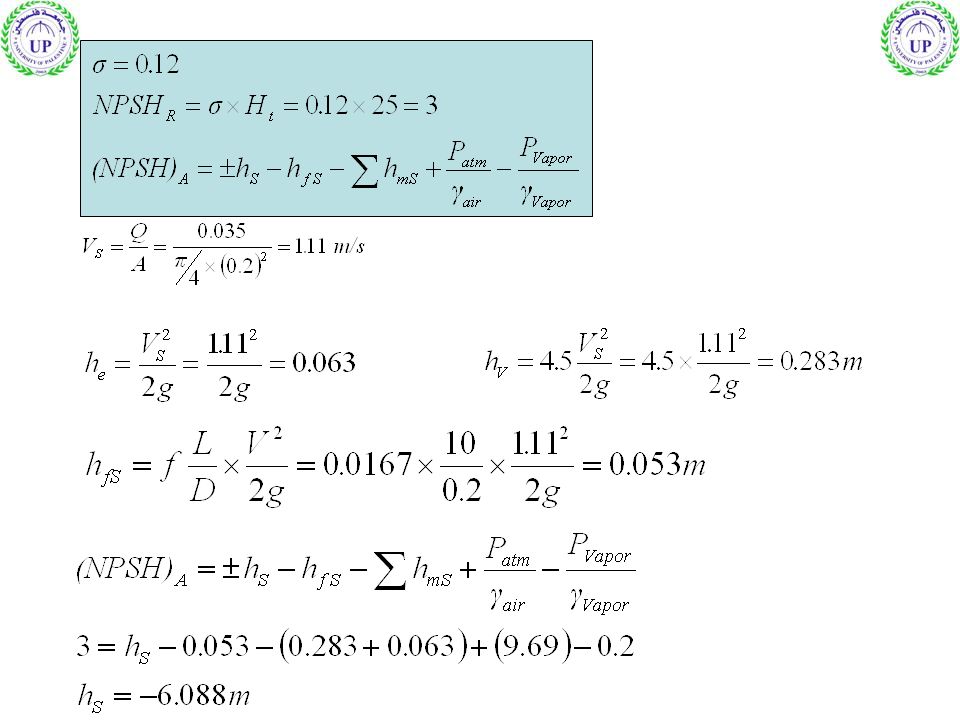
Example 1 A Pump has a cavitation constant = 0.12, this pump was instructed on well using UPVC pipe of 10m length and 200mm diameter, there are elbow (ke=1) and valve (ke=4.5) in the system. the flow is 35m3 and The total Dynamic Head Ht = 25m (from pump curve) f=0.0167 Calculate the maximum suction head
 and valve (ke=4.5) in the system. the flow is 35m3 and The total Dynamic Head Ht = 25m (from pump curve) f= Calculate the maximum suction head.")
13
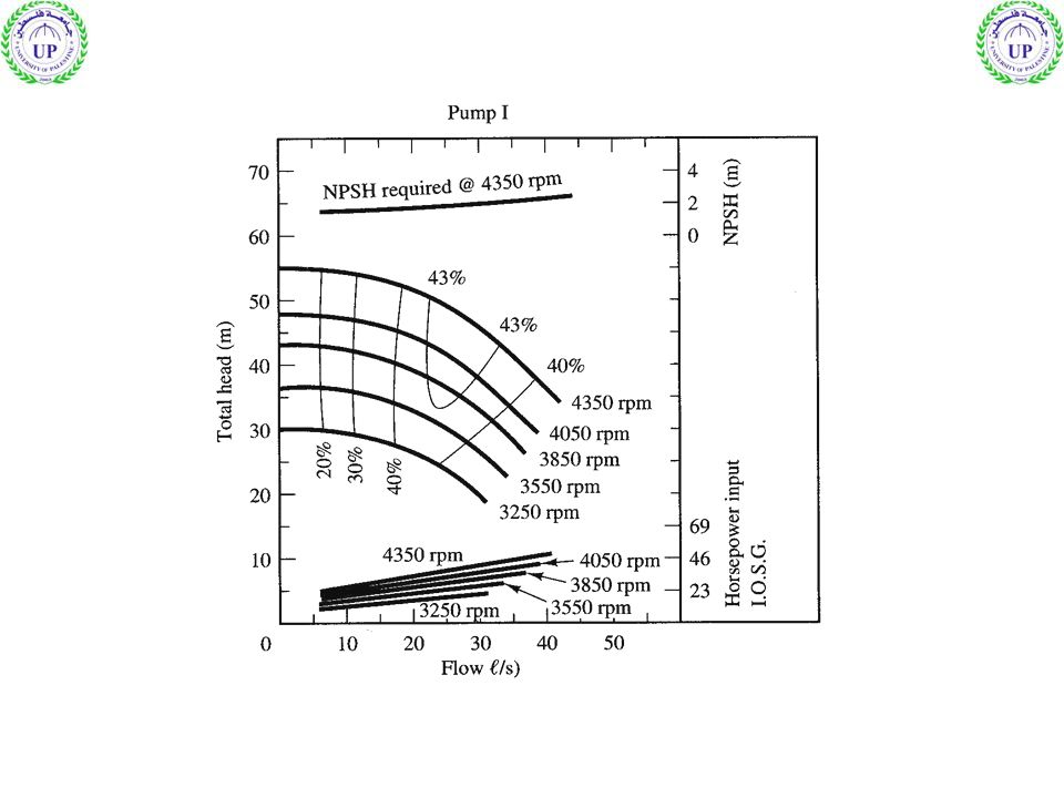
Example 2 For the following pump, determine the required pipes diameter to pump 60 L/s and also calculate the needed power. Minor losses 10 v2/2g Pipe length 10 km roughness = 0.15 mm hs = 20 m 10 20 30 40 50 60 70 Q L/s 45 44.7 43.7 42.5 40.6 38 35 31 Ht - 57 53

14
To get 60 L/s from the pump hs + hL must be < 35 m
Assume the diameter = 300mm Then:

15
Assume the diameter = 350mm
Then:

16
Example 3 A pump was designed to satisfy the following system 9 6 3
Q (m3/hr) 38 20 12 hf (m) Check whether the pump is suitable or not Pipe diameter is 50mm
 hf (m) Check whether the pump is suitable or not. Pipe diameter is 50mm.")
18
1- Draw the system curve and check the operation point

19
pump is not suitable, the cavitation will occur
There are an operation point at: Q = 9 m3/hr H =58m NPSHR =4.1 Then Check NPSHA pump is not suitable, the cavitation will occur

21
Pumps in series & Parallel
Pumps in Parallel:

23
Pumps in series:

25
Change in pump speed (constant size)
")
26
Example 4

27
Solution

29
Home Work

Similar presentations


 Principles of hydraulics 1.Conservation of energy 2.Continuity (conservation of mass)>")


 Water requirements for students and staff at.>")