Download presentation
Presentation is loading. Please wait.

1
INTRODUCTION

2
CONSTRUCTION A 3-phase induction motor has two main parts (i) stator and (ii) rotor. The rotor is separated from the stator by a small air-gap which ranges from 0.4 mm to 4 mm, depending on the power of the motor. 1)STATOR It consists of a steel frame which encloses a hollow, cylindrical core made up of thin laminations of silicon steel to reduce hysteresis and eddy current losses. The insulated conductors are connected to form a balanced 3-phase star or delta connected circuit. The 3-phase stator winding is wound for a definite number of poles as per requirement of speed. Greater the number of poles, lesser is the speed of the motor and vice-versa. When 3-phase supply is given to the stator winding, a rotating magnetic field of constant magnitude is produced. This rotating field induces currents in the rotor by electromagnetic induction.
 stator and (ii) rotor. The rotor is separated from the stator by a small air-gap which ranges from 0.4 mm to 4 mm, depending on the power of the motor. 1)STATOR. It consists of a steel frame which encloses a hollow, cylindrical. core made up of thin laminations of silicon steel to reduce hysteresis and eddy current losses. The insulated conductors are connected to form a balanced 3-phase star or delta connected circuit. The 3-phase stator winding is wound for a definite number of poles as per requirement of speed. Greater the number of poles, lesser is the speed of the motor and vice-versa. When 3-phase supply is given to the stator winding, a rotating magnetic field of constant magnitude is produced. This rotating field induces currents in the rotor by electromagnetic induction.")
3
2. ROTOR

4
SQUIRREL CAGE ROTOR. It consists of a laminated cylindrical core having parallel slots on its outer periphery. One copper or aluminum bar is placed in each slot. All these bars are joined at each end by metal rings called end rings . This forms a permanently short-circuited Winding which is indestructible. The rotor is not connected electrically to the supply but has current induced in it by transformer action from the stator. However, it suffers from the disadvantage of a low starting torque. It is because the rotor bars are permanently short-circuited and it is not possible to add anyexternal resistance to the rotor circuit to have a large starting torque.

6
(ii) WOUND ROTOR. The open ends of the rotor winding are brought out and joined to three insulated slip rings mounted on the rotor shaft with one brush resting on each slip ring. The three brushes are connected to a 3-phase star-connected rheostat as shown in Fig. At starting, the external resistances are included in the rotor circuit to give a large starting torque. These resistances are gradually reduced to zero as the motor runs up to speed.

8
SINGLE PHASE INDUCTION MOTOR
Single-phase motors are the most familiar of all electric motors because they are extensively used in home appliances, shops, offices etc. It is true that single-phase motors are less efficient substitute for 3-phase motors but 3-phase power is normally not available except in large commercial and industrial establishments. Since electric power was originally generated and distributed for lighting only, millions of homes were given single-phase supply. This led to the development of single-phase motors.

10
Single-Phase Induction Motors
A single phase induction motor is very similar to a 3-phase squirrel cage induction motor. It has (i) a squirrel-cage rotor identical to a 3-phase motor and (ii) a single-phase winding on the stator Unlike a 3-phase induction motor, a single-phase induction motor is not self-starting but requires some starting means. The single-phase stator winding produces a magnetic field that pulsates in strength in a sinusoidal manner. The field polarity reverses after each half cycle but the field does not rotate.
 a squirrel-cage rotor identical to a 3-phase motor and. (ii) a single-phase winding on the stator. Unlike a 3-phase induction motor, a single-phase induction motor is not self-starting but requires some starting means. The single-phase stator winding produces a magnetic field that pulsates in strength in a sinusoidal manner. The field polarity reverses after each half cycle but the field does not rotate.")
11
Consequently, the alternating flux cannot produce rotation in a stationary squirrel-cage rotor.
However, if the rotor of a single-phase motor is rotated in one direction by some mechanical means, it will continue to run in the direction of rotation. This method of starting is generally not convenient for large motors.

12
Making Single-Phase Induction Motor Self-Starting
To make a single-phase induction motor self-starting, we should somehow produce a revolving stator magnetic field. This may be achieved by converting a single-phase supply into two-phase supply through the use of an additional winding. When the motor attains sufficient speed, the starting means (i.e., additional winding) may be removed depending upon the type of the motor. As a matter of fact, single-phase induction motors are classified and named according to the method employed to make them self-starting
 may be removed depending upon the type of the motor. As a matter of fact, single-phase induction motors are classified and named according to the method employed to make them self-starting.")
14
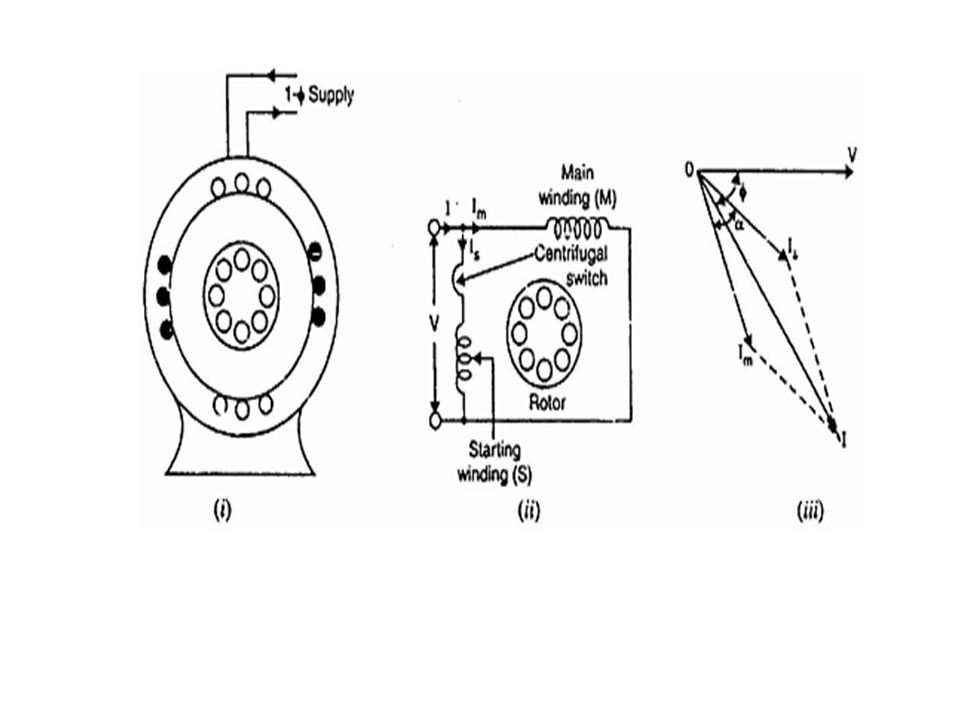
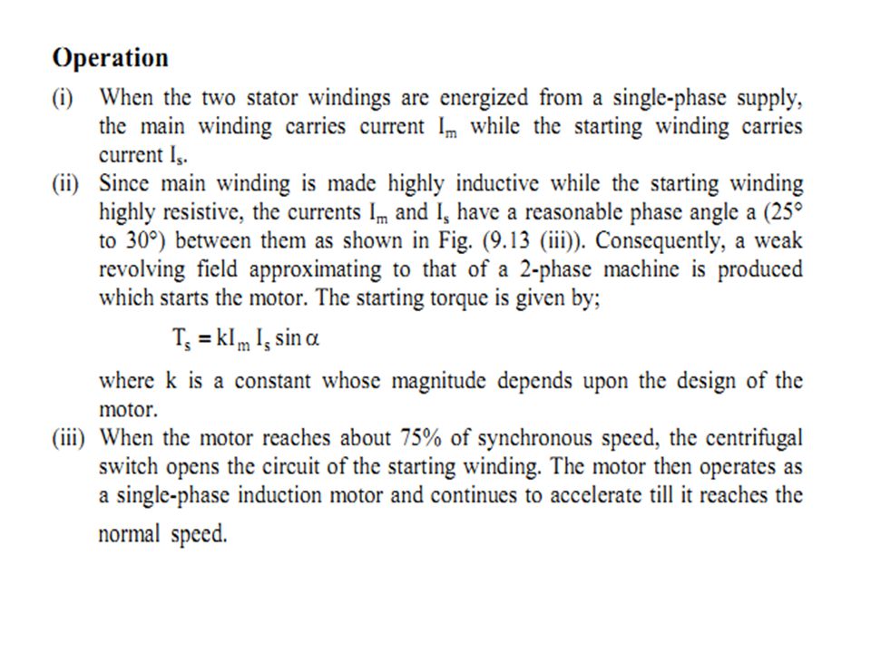
1)Split-Phase Induction Motor
The stator of a split-phase induction motor is provided with an auxiliary or starting winding S in addition to the main or running winding M. The starting winding is located 90° electrical from the main winding and operates only during the brief period when the motor starts up. The two windings are so resigned that the starting winding S has a high resistance and relatively small reactance while the main winding M has relatively low resistance and large reactance. Consequently, the currents flowing in the two windings have reasonable phase difference c (25° to 30°) as shown in the phasor diagram
 as shown in the phasor diagram.")
17
CAPACITOR-START MOTOR

Similar presentations


>")


