Download presentation
Presentation is loading. Please wait.

1
Electricity, Components and Circuits
CHAPTER 3 Electricity, Components and Circuits

2
Background and concepts
Microhams 2010 Technician

3
Ohm’s Law and Power Calculations
To solve for a value, cover it with your finger and solve the remaining formula E P I R I E There is a relationship between voltage, current and resistance as shown by the circle above. To solve for a value, cover it with your finger and solve the remaining formula. Ohm’s law states: E=IxR, I=E/R, R=E/I. The power formula states: P=IxE, I=P/E, E=P/I There is one more formula that can be derived from this. Since Ohm’s law states E=IxR, you can substitute E in the power formula with this value yielding P=Ix(IxR) or P=I^2xR. E=Voltage (Volts) I=Current (Amps) R=Resistance (Ohms) P=Power (Watts) Radio and Electronic Fundamentals
 or P=I^2xR. E=Voltage (Volts) I=Current (Amps) R=Resistance (Ohms) P=Power (Watts) Radio and Electronic Fundamentals.")
4
Voltage, Current and Power
Potential – Electromotive Force Electromotive Force (E) Units – Volts Unit Symbol V – 10V Measured across (parallel to load) Current – Electron flow Current (I) Unites – Amps, Amperes Unit Symbol A – 0.1A Measured through (inline with load) Power (P) Watts Units – Watts Unit Symbol W – 60W P I E Potential – Voltage or Electromotive force Units are Volts named after Count Alessandro Giuseppe Antonio Anastasio Volta (Italian Inventor), invented the baterry. Flow – Current, measured in amps, named after André-Marie Ampère (French) scientist and mathematician. I is used as the abbreviation because it referred to the Intensity of the current. Power – Measured in Watts, named after James Watt (Scottish/British) inventor P = I x E Radio and Electronic Fundamentals
 Units – Volts. Unit Symbol V – 10V. Measured across (parallel to load) Current – Electron flow. Current (I) Unites – Amps, Amperes. Unit Symbol A – 0.1A. Measured through (inline with load) Power (P) Watts. Units – Watts. Unit Symbol W – 60W. P. I. E. Potential – Voltage or Electromotive force. Units are Volts named after Count Alessandro Giuseppe Antonio Anastasio Volta (Italian Inventor), invented the baterry. Flow – Current, measured in amps, named after André-Marie Ampère (French) scientist and mathematician. I is used as the abbreviation because it referred to the Intensity of the current. Power – Measured in Watts, named after James Watt (Scottish/British) inventor. P = I x E. Radio and Electronic Fundamentals.")
5
T5A11 What is the basic unit of electromotive force?
A. The volt B. The watt C. The ampere D. The ohm

6
T5A11 What is the basic unit of electromotive force?
A. The volt B. The watt C. The ampere D. The ohm

7
T5A01 Electrical current is measured in which of the following units?
A. Volts B. Watts C. Ohms D. Amperes

8
T5A01 Electrical current is measured in which of the following units?
A. Volts B. Watts C. Ohms D. Amperes

9
T5A03 What is the name for the flow of electrons in an electric circuit?
A. Voltage B. Resistance C. Capacitance D. Current

10
T5A03 What is the name for the flow of electrons in an electric circuit?
A. Voltage B. Resistance C. Capacitance D. Current

11
T5A05 What is the electrical term for the electromotive force (EMF) that causes electron flow?
A. Voltage B. Ampere-hours C. Capacitance D. Inductance

12
T5A05 What is the electrical term for the electromotive force (EMF) that causes electron flow?
A. Voltage B. Ampere-hours C. Capacitance D. Inductance

13
T5A10 Which term describes the rate at which electrical energy is used?
A. Resistance B. Current C. Power D. Voltage

14
T5A10 Which term describes the rate at which electrical energy is used?
A. Resistance B. Current C. Power D. Voltage

15
T7D01 Which instrument would you use to measure electric potential or electromotive force?
A. An ammeter B. A voltmeter C. A wavemeter D. An ohmmeter

16
T7D01 Which instrument would you use to measure electric potential or electromotive force?
A. An ammeter B. A voltmeter C. A wavemeter D. An ohmmeter

17
T7D02 What is the correct way to connect a voltmeter to a circuit?
A. In series with the circuit B. In parallel with the circuit C. In quadrature with the circuit D. In phase with the circuit

18
T7D02 What is the correct way to connect a voltmeter to a circuit?
A. In series with the circuit B. In parallel with the circuit C. In quadrature with the circuit D. In phase with the circuit

19
T7D03 How is an ammeter usually connected to a circuit?
A. In series with the circuit B. In parallel with the circuit C. In quadrature with the circuit D. In phase with the circuit

20
T7D03 How is an ammeter usually connected to a circuit?
A. In series with the circuit B. In parallel with the circuit C. In quadrature with the circuit D. In phase with the circuit

21
T5A07 Which of the following is a good electrical conductor?
A. Glass B. Wood C. Copper D. Rubber

22
T5A07 Which of the following is a good electrical conductor?
A. Glass B. Wood C. Copper D. Rubber

23
T7D04 Which instrument is used to measure electric current?
A. An ohmmeter B. A wavemeter C. A voltmeter D. An ammeter

24
T7D04 Which instrument is used to measure electric current?
A. An ohmmeter B. A wavemeter C. A voltmeter D. An ammeter

25
T5A08 Which of the following is a good electrical insulator?
A. Copper B. Glass C. Aluminum D. Mercury

26
T5A08 Which of the following is a good electrical insulator?
A. Copper B. Glass C. Aluminum D. Mercury

27
T5D01 What formula is used to calculate current in a circuit?
A. Current (I) equals voltage (E) multiplied by resistance (R) B. Current (I) equals voltage (E) divided by resistance (R) C. Current (I) equals voltage (E) added to resistance (R) D. Current (I) equals voltage (E) minus resistance (R)
 equals voltage (E) multiplied by resistance (R) B. Current (I) equals voltage (E) divided by resistance (R) C. Current (I) equals voltage (E) added to resistance (R) D. Current (I) equals voltage (E) minus resistance (R)")
28
Ohm’s Law and Power Calculations
To solve for a value, cover it with your finger and solve the remaining formula E P I R I E There is a relationship between voltage, current and resistance as shown by the circle above. To solve for a value, cover it with your finger and solve the remaining formula. Ohm’s law states: E=IxR, I=E/R, R=E/I. The power formula states: P=IxE, I=P/E, E=P/I There is one more formula that can be derived from this. Since Ohm’s law states E=IxR, you can substitute E in the power formula with this value yielding P=Ix(IxR) or P=I^2xR. E=Voltage (Volts) I=Current (Amps) R=Resistance (Ohms) P=Power (Watts) Radio and Electronic Fundamentals
 or P=I^2xR. E=Voltage (Volts) I=Current (Amps) R=Resistance (Ohms) P=Power (Watts) Radio and Electronic Fundamentals.")
29
T5D01 What formula is used to calculate current in a circuit?
A. Current (I) equals voltage (E) multiplied by resistance (R) B. Current (I) equals voltage (E) divided by resistance (R) C. Current (I) equals voltage (E) added to resistance (R) D. Current (I) equals voltage (E) minus resistance (R)
 equals voltage (E) multiplied by resistance (R) B. Current (I) equals voltage (E) divided by resistance (R) C. Current (I) equals voltage (E) added to resistance (R) D. Current (I) equals voltage (E) minus resistance (R)")
30
T5D02 What formula is used to calculate voltage in a circuit?
A. Voltage (E) equals current (I) multiplied by resistance (R) B. Voltage (E) equals current (I) divided by resistance (R) C. Voltage (E) equals current (I) added to resistance (R) D. Voltage (E) equals current (I) minus resistance (R)
 equals current (I) multiplied by resistance (R) B. Voltage (E) equals current (I) divided by resistance (R) C. Voltage (E) equals current (I) added to resistance (R) D. Voltage (E) equals current (I) minus resistance (R)")
31
Ohm’s Law and Power Calculations
To solve for a value, cover it with your finger and solve the remaining formula E P I R I E There is a relationship between voltage, current and resistance as shown by the circle above. To solve for a value, cover it with your finger and solve the remaining formula. Ohm’s law states: E=IxR, I=E/R, R=E/I. The power formula states: P=IxE, I=P/E, E=P/I There is one more formula that can be derived from this. Since Ohm’s law states E=IxR, you can substitute E in the power formula with this value yielding P=Ix(IxR) or P=I^2xR. E=Voltage (Volts) I=Current (Amps) R=Resistance (Ohms) P=Power (Watts) Radio and Electronic Fundamentals
 or P=I^2xR. E=Voltage (Volts) I=Current (Amps) R=Resistance (Ohms) P=Power (Watts) Radio and Electronic Fundamentals.")
32
T5D02 What formula is used to calculate voltage in a circuit?
A. Voltage (E) equals current (I) multiplied by resistance (R) B. Voltage (E) equals current (I) divided by resistance (R) C. Voltage (E) equals current (I) added to resistance (R) D. Voltage (E) equals current (I) minus resistance (R)
 equals current (I) multiplied by resistance (R) B. Voltage (E) equals current (I) divided by resistance (R) C. Voltage (E) equals current (I) added to resistance (R) D. Voltage (E) equals current (I) minus resistance (R)")
33
T5D03 What formula is used to calculate resistance in a circuit?
A. Resistance (R) equals voltage (E) multiplied by current (I) B. Resistance (R) equals voltage (E) divided by current (I) C. Resistance (R) equals voltage (E) added to current (I) D. Resistance (R) equals voltage (E) minus current (I)
 equals voltage (E) multiplied by current (I) B. Resistance (R) equals voltage (E) divided by current (I) C. Resistance (R) equals voltage (E) added to current (I) D. Resistance (R) equals voltage (E) minus current (I)")
34
Ohm’s Law and Power Calculations
To solve for a value, cover it with your finger and solve the remaining formula E P I R I E There is a relationship between voltage, current and resistance as shown by the circle above. To solve for a value, cover it with your finger and solve the remaining formula. Ohm’s law states: E=IxR, I=E/R, R=E/I. The power formula states: P=IxE, I=P/E, E=P/I There is one more formula that can be derived from this. Since Ohm’s law states E=IxR, you can substitute E in the power formula with this value yielding P=Ix(IxR) or P=I^2xR. E=Voltage (Volts) I=Current (Amps) R=Resistance (Ohms) P=Power (Watts) Radio and Electronic Fundamentals
 or P=I^2xR. E=Voltage (Volts) I=Current (Amps) R=Resistance (Ohms) P=Power (Watts) Radio and Electronic Fundamentals.")
35
T5D03 What formula is used to calculate resistance in a circuit?
A. Resistance (R) equals voltage (E) multiplied by current (I) B. Resistance (R) equals voltage (E) divided by current (I) C. Resistance (R) equals voltage (E) added to current (I) D. Resistance (R) equals voltage (E) minus current (I)
 equals voltage (E) multiplied by current (I) B. Resistance (R) equals voltage (E) divided by current (I) C. Resistance (R) equals voltage (E) added to current (I) D. Resistance (R) equals voltage (E) minus current (I)")
36
T5D04 What is the resistance of a circuit in which a current of 3 amperes flows through a resistor connected to 90 volts? A. 3 ohms B. 30 ohms C. 93 ohms D. 270 ohms

37
T5D04 What is the resistance of a circuit in which a current of 3 amperes flows through a resistor connected to 90 volts? E I R R = E / I R = 90 V 3 A = 30Ω There is a relationship between voltage, current and resistance as shown by the circle above. To solve for a value, cover it with your finger and solve the remaining formula. Ohm’s law states: E=IxR, I=E/R, R=E/I. The power formula states: P=IxE, I=P/E, E=P/I There is one more formula that can be derived from this. Since Ohm’s law states E=IxR, you can substitute E in the power formula with this value yielding P=Ix(IxR) or P=I^2xR. Radio and Electronic Fundamentals
 or P=I^2xR. Radio and Electronic Fundamentals.")
38
T5D04 What is the resistance of a circuit in which a current of 3 amperes flows through a resistor connected to 90 volts? A. 3 ohms B. 30 ohms C. 93 ohms D. 270 ohms

39
T5D05 What is the resistance in a circuit for which the applied voltage is 12 volts and the current flow is 1.5 amperes? A. 18 ohms B ohms C. 8 ohms D ohms

40
T5D05 What is the resistance in a circuit for which the applied voltage is 12 volts and the current flow is 1.5 amperes? E I R R = E / I R = 12 V 1.5 A = 8 Ω There is a relationship between voltage, current and resistance as shown by the circle above. To solve for a value, cover it with your finger and solve the remaining formula. Ohm’s law states: E=IxR, I=E/R, R=E/I. The power formula states: P=IxE, I=P/E, E=P/I There is one more formula that can be derived from this. Since Ohm’s law states E=IxR, you can substitute E in the power formula with this value yielding P=Ix(IxR) or P=I^2xR. Radio and Electronic Fundamentals
 or P=I^2xR. Radio and Electronic Fundamentals.")
41
T5D05 What is the resistance in a circuit for which the applied voltage is 12 volts and the current flow is 1.5 amperes? A. 18 ohms B ohms C. 8 ohms D ohms

42
T5D06 What is the resistance of a circuit that draws 4 amperes from a 12-volt source?
A. 3 ohms B. 16 ohms C. 48 ohms D. 8 Ohms

43
T5D06 What is the resistance of a circuit that draws 4 amperes from a 12-volt source?
R = E / I R = 12 V 4 A = 3 Ω There is a relationship between voltage, current and resistance as shown by the circle above. To solve for a value, cover it with your finger and solve the remaining formula. Ohm’s law states: E=IxR, I=E/R, R=E/I. The power formula states: P=IxE, I=P/E, E=P/I There is one more formula that can be derived from this. Since Ohm’s law states E=IxR, you can substitute E in the power formula with this value yielding P=Ix(IxR) or P=I^2xR. Radio and Electronic Fundamentals
 or P=I^2xR. Radio and Electronic Fundamentals.")
44
T5D06 What is the resistance of a circuit that draws 4 amperes from a 12-volt source?
A. 3 ohms B. 16 ohms C. 48 ohms D. 8 Ohms

45
T5D07 What is the current flow in a circuit with an applied voltage of 120 volts and a resistance of 80 ohms? A amperes B. 200 amperes C amperes D. 1.5 amperes

46
T5D07 What is the current flow in a circuit with an applied voltage of 120 volts and a resistance of 80 ohms? E I = E / R I = 120V 80Ω = 1.5A I R There is a relationship between voltage, current and resistance as shown by the circle above. To solve for a value, cover it with your finger and solve the remaining formula. Ohm’s law states: E=IxR, I=E/R, R=E/I. The power formula states: P=IxE, I=P/E, E=P/I There is one more formula that can be derived from this. Since Ohm’s law states E=IxR, you can substitute E in the power formula with this value yielding P=Ix(IxR) or P=I^2xR. Radio and Electronic Fundamentals
 or P=I^2xR. Radio and Electronic Fundamentals.")
47
T5D07 What is the current flow in a circuit with an applied voltage of 120 volts and a resistance of 80 ohms? A amperes B. 200 amperes C amperes D. 1.5 amperes

48
T5D08 What is the current flowing through a 100-ohm resistor connected across 200 volts?
A. 20,000 amperes B. 0.5 amperes C. 2 amperes D. 100 amperes

49
T5D08 What is the current flowing through a 100-ohm resistor connected across 200 volts?
I = E / R I = 200V 100Ω = 2 A I R There is a relationship between voltage, current and resistance as shown by the circle above. To solve for a value, cover it with your finger and solve the remaining formula. Ohm’s law states: E=IxR, I=E/R, R=E/I. The power formula states: P=IxE, I=P/E, E=P/I There is one more formula that can be derived from this. Since Ohm’s law states E=IxR, you can substitute E in the power formula with this value yielding P=Ix(IxR) or P=I^2xR. Radio and Electronic Fundamentals
 or P=I^2xR. Radio and Electronic Fundamentals.")
50
T5D08 What is the current flowing through a 100-ohm resistor connected across 200 volts?
A. 20,000 amperes B. 0.5 amperes C. 2 amperes D. 100 amperes

51
T5D09 What is the current flowing through a 24-ohm resistor connected across 240 volts?
A. 24,000 amperes B. 0.1 amperes C. 10 amperes D. 216 amperes

52
T5D09 What is the current flowing through a 24-ohm resistor connected across 240 volts?
I = E / R I = 240V 24Ω = 10 A I R There is a relationship between voltage, current and resistance as shown by the circle above. To solve for a value, cover it with your finger and solve the remaining formula. Ohm’s law states: E=IxR, I=E/R, R=E/I. The power formula states: P=IxE, I=P/E, E=P/I There is one more formula that can be derived from this. Since Ohm’s law states E=IxR, you can substitute E in the power formula with this value yielding P=Ix(IxR) or P=I^2xR. Radio and Electronic Fundamentals
 or P=I^2xR. Radio and Electronic Fundamentals.")
53
T5D09 What is the current flowing through a 24-ohm resistor connected across 240 volts?
A. 24,000 amperes B. 0.1 amperes C. 10 amperes D. 216 amperes

54
T5D10 What is the voltage across a 2-ohm resistor if a current of 0
T5D10 What is the voltage across a 2-ohm resistor if a current of 0.5 amperes flows through it? A. 1 volt B volts C. 2.5 volts D. 1.5 volts

55
T5D10 What is the voltage across a 2-ohm resistor if a current of 0
T5D10 What is the voltage across a 2-ohm resistor if a current of 0.5 amperes flows through it? E I R E = I * R E = 0.5A x 2Ω = 1V There is a relationship between voltage, current and resistance as shown by the circle above. To solve for a value, cover it with your finger and solve the remaining formula. Ohm’s law states: E=IxR, I=E/R, R=E/I. The power formula states: P=IxE, I=P/E, E=P/I There is one more formula that can be derived from this. Since Ohm’s law states E=IxR, you can substitute E in the power formula with this value yielding P=Ix(IxR) or P=I^2xR. Radio and Electronic Fundamentals
 or P=I^2xR. Radio and Electronic Fundamentals.")
56
T5D10 What is the voltage across a 2-ohm resistor if a current of 0
T5D10 What is the voltage across a 2-ohm resistor if a current of 0.5 amperes flows through it? A. 1 volt B volts C. 2.5 volts D. 1.5 volts

57
T5D11 What is the voltage across a 10-ohm resistor if a current of 1 ampere flows through it?
A. 1 volt B. 10 volts C. 11 volts D. 9 volts

58
T5D11 What is the voltage across a 10-ohm resistor if a current of 1 amperes flows through it?
E = I * R E = 1 A x 10Ω = 10V There is a relationship between voltage, current and resistance as shown by the circle above. To solve for a value, cover it with your finger and solve the remaining formula. Ohm’s law states: E=IxR, I=E/R, R=E/I. The power formula states: P=IxE, I=P/E, E=P/I There is one more formula that can be derived from this. Since Ohm’s law states E=IxR, you can substitute E in the power formula with this value yielding P=Ix(IxR) or P=I^2xR. Radio and Electronic Fundamentals
 or P=I^2xR. Radio and Electronic Fundamentals.")
59
T5D11 What is the voltage across a 10-ohm resistor if a current of 1 ampere flows through it?
A. 1 volt B. 10 volts C. 11 volts D. 9 volts

60
T5D12 What is the voltage across a 10-ohm resistor if a current of 2 amperes flows through it?
A. 8 volts B. 0.2 volts C. 12 volts D. 20 volts

61
T5D12 What is the voltage across a 10-ohm resistor if a current of 2 amperes flows through it?
E = I * R E = 2 A x 10Ω = 20V There is a relationship between voltage, current and resistance as shown by the circle above. To solve for a value, cover it with your finger and solve the remaining formula. Ohm’s law states: E=IxR, I=E/R, R=E/I. The power formula states: P=IxE, I=P/E, E=P/I There is one more formula that can be derived from this. Since Ohm’s law states E=IxR, you can substitute E in the power formula with this value yielding P=Ix(IxR) or P=I^2xR. Radio and Electronic Fundamentals
 or P=I^2xR. Radio and Electronic Fundamentals.")
62
T5D12 What is the voltage across a 10-ohm resistor if a current of 2 amperes flows through it?
A. 8 volts B. 0.2 volts C. 12 volts D. 20 volts

63
T7D05 What instrument is used to measure resistance?
A. An oscilloscope B. A spectrum analyzer C. A noise bridge D. An ohmmeter

64
T7D05 What instrument is used to measure resistance?
A. An oscilloscope B. A spectrum analyzer C. A noise bridge D. An ohmmeter

65
T7D11 Which of the following precautions should be taken when measuring circuit resistance with an ohmmeter? A. Ensure that the applied voltages are correct B. Ensure that the circuit is not powered C. Ensure that the circuit is grounded D. Ensure that the circuit is operating at the correct frequency

66
T7D11 Which of the following precautions should be taken when measuring circuit resistance with an ohmmeter? A. Ensure that the applied voltages are correct B. Ensure that the circuit is not powered C. Ensure that the circuit is grounded D. Ensure that the circuit is operating at the correct frequency

67
T7D12 Which of the following precautions should be taken when measuring high voltages with a voltmeter? A. Ensure that the voltmeter has very low impedance B. Ensure that the voltmeter and leads are rated for use at the voltages to be measured C. Ensure that the circuit is grounded through the voltmeter D. Ensure that the voltmeter is set to the correct frequency

68
T7D12 Which of the following precautions should be taken when measuring high voltages with a voltmeter? A. Ensure that the voltmeter has very low impedance B. Ensure that the voltmeter and leads are rated for use at the voltages to be measured C. Ensure that the circuit is grounded through the voltmeter D. Ensure that the voltmeter is set to the correct frequency

69
T7D07 Which of the following measurements are commonly made using a multimeter?
A. SWR and RF power B. Signal strength and noise C. Impedance and reactance D. Voltage and resistance

70
T7D07 Which of the following measurements are commonly made using a multimeter?
A. SWR and RF power B. Signal strength and noise C. Impedance and reactance D. Voltage and resistance

71
T7D06 Which of the following might damage a multimeter?
A. Measuring a voltage too small for the chosen scale B. Leaving the meter in the milliamps position overnight C. Attempting to measure voltage when using the resistance setting D. Not allowing it to warm up properly

72
T7D06 Which of the following might damage a multimeter?
A. Measuring a voltage too small for the chosen scale B. Leaving the meter in the milliamps position overnight C. Attempting to measure voltage when using the resistance setting D. Not allowing it to warm up properly

73
T7D10 What is probably happening when an ohmmeter, connected across an unpowered circuit, initially indicates a low resistance and then shows increasing resistance with time? A. The ohmmeter is defective B. The circuit contains a large capacitor C. The circuit contains a large inductor D. The circuit is a relaxation oscillator

74
T7D10 What is probably happening when an ohmmeter, connected across an unpowered circuit, initially indicates a low resistance and then shows increasing resistance with time? A. The ohmmeter is defective B. The circuit contains a large capacitor C. The circuit contains a large inductor D. The circuit is a relaxation oscillator

75
T5A02 Electrical power is measured in which of the following units?
A. Volts B. Watts C. Ohms D. Amperes

76
T5A02 Electrical power is measured in which of the following units?
A. Volts B. Watts C. Ohms D. Amperes

77
Direct Current Alternating Current
DC Current flows in one direction only Examples: Battery Operated Devices Cars AC Current flows in both directions, voltage and current very with time Example: House Wiring Radio and Electronic Fundamentals

78
T5A04 What is the name for a current that flows only in one direction?
A. Alternating current B. Direct current C. Normal current D. Smooth current

79
T5A04 What is the name for a current that flows only in one direction?
A. Alternating current B. Direct current C. Normal current D. Smooth current

80
T5A09 What is the name for a current that reverses direction on a regular basis?
A. Alternating current B. Direct current C. Circular current D. Vertical current

81
T5A09 What is the name for a current that reverses direction on a regular basis?
A. Alternating current B. Direct current C. Circular current D. Vertical current

82
Voltage, Current and Power
Potential – Electromotive Force Electromotive Force (E) Units – Volts Unit Symbol V – 10V Measured across (parallel to load) Current – Electron flow Current (I) Unites – Amps, Amperes Unit Symbol A – 0.1A Measured through (inline with load) Power (P) Watts Units – Watts Unit Symbol W – 60W P I E Potential – Voltage or Electromotive force Units are Volts named after Count Alessandro Giuseppe Antonio Anastasio Volta (Italian Inventor), invented the baterry. Flow – Current, measured in amps, named after André-Marie Ampère (French) scientist and mathematician. I is used as the abbreviation because it referred to the Intensity of the current. Power – Measured in Watts, named after James Watt (Scottish/British) inventor P = I x E Radio and Electronic Fundamentals
 Units – Volts. Unit Symbol V – 10V. Measured across (parallel to load) Current – Electron flow. Current (I) Unites – Amps, Amperes. Unit Symbol A – 0.1A. Measured through (inline with load) Power (P) Watts. Units – Watts. Unit Symbol W – 60W. P. I. E. Potential – Voltage or Electromotive force. Units are Volts named after Count Alessandro Giuseppe Antonio Anastasio Volta (Italian Inventor), invented the baterry. Flow – Current, measured in amps, named after André-Marie Ampère (French) scientist and mathematician. I is used as the abbreviation because it referred to the Intensity of the current. Power – Measured in Watts, named after James Watt (Scottish/British) inventor. P = I x E. Radio and Electronic Fundamentals.")
83
T5C08 What is the formula used to calculate electrical power in a DC circuit?
A. Power (P) equals voltage (E) multiplied by current (I) B. Power (P) equals voltage (E) divided by current (I) C. Power (P) equals voltage (E) minus current (I) D. Power (P) equals voltage (E) plus current (I)
 equals voltage (E) multiplied by current (I) B. Power (P) equals voltage (E) divided by current (I) C. Power (P) equals voltage (E) minus current (I) D. Power (P) equals voltage (E) plus current (I)")
84
T5C08 What is the formula used to calculate electrical power in a DC circuit?
A. Power (P) equals voltage (E) multiplied by current (I) B. Power (P) equals voltage (E) divided by current (I) C. Power (P) equals voltage (E) minus current (I) D. Power (P) equals voltage (E) plus current (I)
 equals voltage (E) multiplied by current (I) B. Power (P) equals voltage (E) divided by current (I) C. Power (P) equals voltage (E) minus current (I) D. Power (P) equals voltage (E) plus current (I)")
85
T5C09 How much power is being used in a circuit when the applied voltage is 13.8 volts DC and the current is 10 amperes? A. 138 watts B. 0.7 watts C watts D. 3.8 watts

86
T5C09 How much power is being used in a circuit when the applied voltage is 13.8 volts DC and the current is 10 amperes? P I E P = I x E There is a relationship between voltage, current and resistance as shown by the circle above. To solve for a value, cover it with your finger and solve the remaining formula. Ohm’s law states: E=IxR, I=E/R, R=E/I. The power formula states: P=IxE, I=P/E, E=P/I There is one more formula that can be derived from this. Since Ohm’s law states E=IxR, you can substitute E in the power formula with this value yielding P=Ix(IxR) or P=I^2xR. Radio and Electronic Fundamentals
 or P=I^2xR. Radio and Electronic Fundamentals.")
87
T5C09 How much power is being used in a circuit when the applied voltage is 13.8 volts DC and the current is 10 amperes? A. 138 watts B. 0.7 watts C watts D. 3.8 watts

88
T5C10 How much power is being used in a circuit when the applied voltage is 12 volts DC and the current is 2.5 amperes? A. 4.8 watts B. 30 watts C watts D watts

89
T5C10 How much power is being used in a circuit when the applied voltage is 12 volts DC and the current is 2.5 amperes? P I E P = I * E P = 2.5 A x 12 V = 30 W There is a relationship between voltage, current and resistance as shown by the circle above. To solve for a value, cover it with your finger and solve the remaining formula. Ohm’s law states: E=IxR, I=E/R, R=E/I. The power formula states: P=IxE, I=P/E, E=P/I There is one more formula that can be derived from this. Since Ohm’s law states E=IxR, you can substitute E in the power formula with this value yielding P=Ix(IxR) or P=I^2xR. Radio and Electronic Fundamentals
 or P=I^2xR. Radio and Electronic Fundamentals.")
90
T5C10 How much power is being used in a circuit when the applied voltage is 12 volts DC and the current is 2.5 amperes? A. 4.8 watts B. 30 watts C watts D watts

91
T5C11 How many amperes are flowing in a circuit when the applied voltage is 12 volts DC and the load is 120 watts? A. 0.1 amperes B. 10 amperes C. 12 amperes D. 132 amperes

92
T5C11 How many amperes are flowing in a circuit when the applied voltage is 12 volts DC and the load is 120 watts? P I E I = P / E I = 120 W 12 VDC = 10A There is a relationship between voltage, current and resistance as shown by the circle above. To solve for a value, cover it with your finger and solve the remaining formula. Ohm’s law states: E=IxR, I=E/R, R=E/I. The power formula states: P=IxE, I=P/E, E=P/I There is one more formula that can be derived from this. Since Ohm’s law states E=IxR, you can substitute E in the power formula with this value yielding P=Ix(IxR) or P=I^2xR. Radio and Electronic Fundamentals
 or P=I^2xR. Radio and Electronic Fundamentals.")
93
T5C11 How many amperes are flowing in a circuit when the applied voltage is 12 volts DC and the load is 120 watts? A. 0.1 amperes B. 10 amperes C. 12 amperes D. 132 amperes

94
T5C01 What is the ability to store energy in an electric field called?
A. Inductance B. Resistance C. Tolerance D. Capacitance

95
T5C01 What is the ability to store energy in an electric field called?
A. Inductance B. Resistance C. Tolerance D. Capacitance

96
T5C02 What is the basic unit of capacitance?
A. The farad B. The ohm C. The volt D. The henry

97
T5C02 What is the basic unit of capacitance?
A. The farad B. The ohm C. The volt D. The henry

98
T5C03 What is the ability to store energy in a magnetic field called?
A. Admittance B. Capacitance C. Resistance D. Inductance

99
T5C03 What is the ability to store energy in a magnetic field called?
A. Admittance B. Capacitance C. Resistance D. Inductance

100
T5C04 What is the basic unit of inductance?
A. The coulomb B. The farad C. The henry D. The ohm

101
T5C04 What is the basic unit of inductance?
A. The coulomb B. The farad C. The henry D. The ohm

102
T6A01 What electrical component is used to oppose the flow of current in a DC circuit?
A. Inductor B. Resistor C. Voltmeter D. Transformer

103
T6A01 What electrical component is used to oppose the flow of current in a DC circuit?
A. Inductor B. Resistor C. Voltmeter D. Transformer

104
T6A02 What type of component is often used as an adjustable volume control?
A. Fixed resistor B. Power resistor C. Potentiometer D. Transformer

105
T6A02 What type of component is often used as an adjustable volume control?
A. Fixed resistor B. Power resistor C. Potentiometer D. Transformer

106
T6A03 What electrical parameter is controlled by a potentiometer?
A. Inductance B. Resistance C. Capacitance D. Field strength

107
T6A03 What electrical parameter is controlled by a potentiometer?
A. Inductance B. Resistance C. Capacitance D. Field strength

108
T6A04 What electrical component stores energy in an electric field?
A. Resistor B. Capacitor C. Inductor D. Diode

109
T6A04 What electrical component stores energy in an electric field?
A. Resistor B. Capacitor C. Inductor D. Diode

110
T6A05 What type of electrical component consists of two or more conductive surfaces separated by an insulator? A. Resistor B. Potentiometer C. Oscillator D. Capacitor

111
T6A05 What type of electrical component consists of two or more conductive surfaces separated by an insulator? A. Resistor B. Potentiometer C. Oscillator D. Capacitor

112
T6A06 What type of electrical component stores energy in a magnetic field?
A. Resistor B. Capacitor C. Inductor D. Diode

113
T6A06 What type of electrical component stores energy in a magnetic field?
A. Resistor B. Capacitor C. Inductor D. Diode

114
T6A07 What electrical component is usually composed of a coil of wire?
A. Switch B. Capacitor C. Diode D. Inductor

115
T6A07 What electrical component is usually composed of a coil of wire?
A. Switch B. Capacitor C. Diode D. Inductor

116
T6D06 What component is commonly used to change 120V AC house current to a lower AC voltage for other uses? A. Variable capacitor B. Transformer C. Transistor D. Diode

117
T6D06 What component is commonly used to change 120V AC house current to a lower AC voltage for other uses? A. Variable capacitor B. Transformer C. Transistor D. Diode

118
T5C12 What is meant by the term impedance?
A. It is a measure of the opposition to AC current flow in a circuit B. It is the inverse of resistance C. It is a measure of the Q or Quality Factor of a component D. It is a measure of the power handling capability of a component

119
T5C12 What is meant by the term impedance?
A. It is a measure of the opposition to AC current flow in a circuit B. It is the inverse of resistance C. It is a measure of the Q or Quality Factor of a component D. It is a measure of the power handling capability of a component

120
T6D08 Which of the following is used together with an inductor to make a tuned circuit?
A. Resistor B. Zener diode C. Potentiometer D. Capacitor

121
T6D08 Which of the following is used together with an inductor to make a tuned circuit?
A. Resistor B. Zener diode C. Potentiometer D. Capacitor

122
T5C13 What are the units of impedance?
A. Volts B. Ampères C. Coulombs D. Ohms

123
T5C13 What are the units of impedance?
A. Volts B. Ampères C. Coulombs D. Ohms

124
T6D09 What is the name of a device that combines several semiconductors and other components into one package? A. Transducer B. Multi-pole relay C. Integrated circuit D. Transformer

125
T6D09 What is the name of a device that combines several semiconductors and other components into one package? A. Transducer B. Multi-pole relay C. Integrated circuit D. Transformer

126
T6B01 What class of electronic components is capable of using a voltage or current signal to control current flow? A. Capacitors B. Inductors C. Resistors D. Transistors

127
T6B01 What class of electronic components is capable of using a voltage or current signal to control current flow? A. Capacitors B. Inductors C. Resistors D. Transistors

128
T6B02 What electronic component allows current to flow in only one direction?
A. Resistor B. Fuse C. Diode D. Driven Element

129
T6B02 What electronic component allows current to flow in only one direction?
A. Resistor B. Fuse C. Diode D. Driven Element

130
T6B03 Which of these components can be used as an electronic switch or amplifier?
A. Oscillator B. Potentiometer C. Transistor D. Voltmeter

131
T6B03 Which of these components can be used as an electronic switch or amplifier?
A. Oscillator B. Potentiometer C. Transistor D. Voltmeter

132
T6B04 Which of the following components can be made of three layers of semiconductor material?
A. Alternator B. Transistor C. Triode D. Pentagrid converter

133
T6B04 Which of the following components can be made of three layers of semiconductor material?
A. Alternator B. Transistor C. Triode D. Pentagrid converter

134
T6B05 Which of the following electronic components can amplify signals?
A. Transistor B. Variable resistor C. Electrolytic capacitor D. Multi-cell battery

135
T6B05 Which of the following electronic components can amplify signals?
A. Transistor B. Variable resistor C. Electrolytic capacitor D. Multi-cell battery

136
T6B06 How is the cathode lead of a semiconductor diode usually identified?
A. With the word cathode B. With a stripe C. With the letter C D. All of these choices are correct

137
T6B06 How is the cathode lead of a semiconductor diode usually identified?
A. With the word cathode B. With a stripe C. With the letter C D. All of these choices are correct

138
T6B07 What does the abbreviation LED stand for?
A. Low Emission Diode B. Light Emitting Diode C. Liquid Emission Detector D. Long Echo Delay

139
T6B07 What does the abbreviation LED stand for?
A. Low Emission Diode B. Light Emitting Diode C. Liquid Emission Detector D. Long Echo Delay

140
T6B08 What does the abbreviation FET stand for?
A. Field Effect Transistor B. Fast Electron Transistor C. Free Electron Transition D. Field Emission Thickness

141
T6B08 What does the abbreviation FET stand for?
A. Field Effect Transistor B. Fast Electron Transistor C. Free Electron Transition D. Field Emission Thickness

142
T6B09 What are the names of the two electrodes of a diode?
A. Plus and minus B. Source and drain C. Anode and cathode D. Gate and base

143
T6B09 What are the names of the two electrodes of a diode?
A. Plus and minus B. Source and drain C. Anode and cathode D. Gate and base

144
T6B10 What are the three electrodes of a PNP or NPN transistor?
A. Emitter, base, and collector B. Source, gate, and drain C. Cathode, grid, and plate D. Cathode, drift cavity, and collector

145
T6B10 What are the three electrodes of a PNP or NPN transistor?
A. Emitter, base, and collector B. Source, gate, and drain C. Cathode, grid, and plate D. Cathode, drift cavity, and collector

146
T6B11 What at are the three electrodes of a field effect transistor?
A. Emitter, base, and collector B. Source, gate, and drain C. Cathode, grid, and plate D. Cathode, gate, and anode

147
T6B11 What at are the three electrodes of a field effect transistor?
A. Emitter, base, and collector B. Source, gate, and drain C. Cathode, grid, and plate D. Cathode, gate, and anode

148
T6B12 What is the term that describes a transistor's ability to amplify a signal?
A. Gain B. Forward resistance C. Forward voltage drop D. On resistance

149
T6B12 What is the term that describes a transistor's ability to amplify a signal?
A. Gain B. Forward resistance C. Forward voltage drop D. On resistance

150
T6D01 Which of the following devices or circuits changes an alternating current into a varying direct current signal? A. Transformer B. Rectifier C. Amplifier D. Reflector

151
T6D01 Which of the following devices or circuits changes an alternating current into a varying direct current signal? A. Transformer B. Rectifier C. Amplifier D. Reflector

152
T6D07 Which of the following is commonly used as a visual indicator?
A. LED B. FET C. Zener diode D. Bipolar transistor

153
T6D07 Which of the following is commonly used as a visual indicator?
A. LED B. FET C. Zener diode D. Bipolar transistor

154
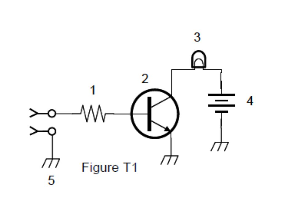
T6D10 What is the function of component 2 in Figure T1?
A. Give off light when current flows through it B. Supply electrical energy C. Control the flow of current D. Convert electrical energy into radio waves

156
T6D10 What is the function of component 2 in Figure T1?
A. Give off light when current flows through it B. Supply electrical energy C. Control the flow of current D. Convert electrical energy into radio waves

157
T6D11 What is a simple resonant or tuned circuit?
A. An inductor and a capacitor connected in series or parallel to form a filter B. A type of voltage regulator C. A resistor circuit used for reducing standing wave ratio D. A circuit designed to provide high fidelity audio

158
T6D11 What is a simple resonant or tuned circuit?
A. An inductor and a capacitor connected in series or parallel to form a filter B. A type of voltage regulator C. A resistor circuit used for reducing standing wave ratio D. A circuit designed to provide high fidelity audio

159
T6A08 What electrical component is used to connect or disconnect electrical circuits?
A. Magnetron B. Switch C. Thermistor D. All of these choices are correct

160
T6A08 What electrical component is used to connect or disconnect electrical circuits?
A. Magnetron B. Switch C. Thermistor D. All of these choices are correct

161
T6A09 What electrical component is used to protect other circuit components from current overloads?
A. Fuse B. Capacitor C. Inductor D. All of these choices are correct

162
T6A09 What electrical component is used to protect other circuit components from current overloads?
A. Fuse B. Capacitor C. Inductor D. All of these choices are correct

163
T6D02 What best describes a relay?
A. A switch controlled by an electromagnet B. A current controlled amplifier C. An optical sensor D. A pass transistor

164
T6D02 What best describes a relay?
A. A switch controlled by an electromagnet B. A current controlled amplifier C. An optical sensor D. A pass transistor

165
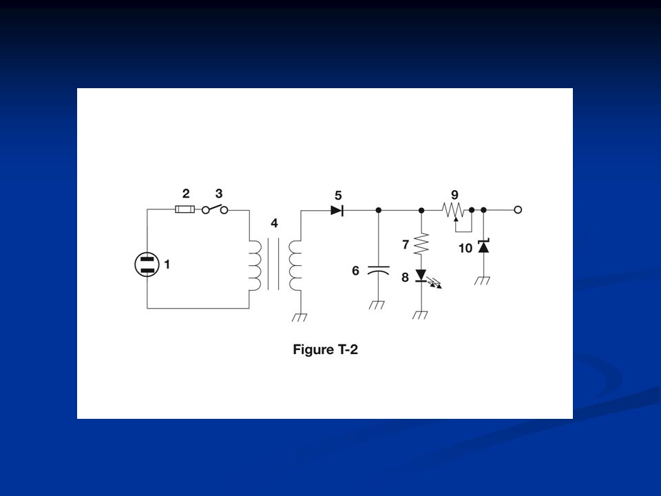
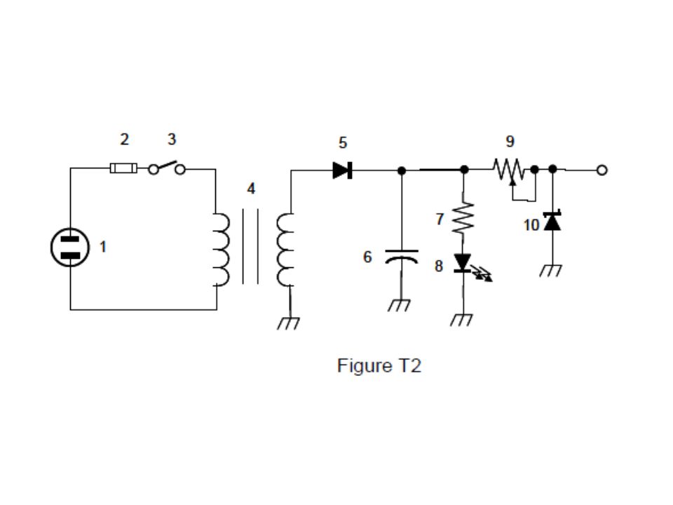
T6D03 What type of switch is represented by component 3 in figure T2?
A. Single-pole single-throw B. Single-pole double-throw C. Double-pole single-throw D. Double-pole double-throw

167
T6D03 What type of switch is represented by component 3 in figure T2?
A. Single-pole single-throw B. Single-pole double-throw C. Double-pole single-throw D. Double-pole double-throw

168
T6D04 Which of the following can be used to display signal strength on a numeric scale?
A. Potentiometer B. Transistor C. Meter D. Relay

169
T6D04 Which of the following can be used to display signal strength on a numeric scale?
A. Potentiometer B. Transistor C. Meter D. Relay

170
T0A04 What is the purpose of a fuse in an electrical circuit?
A. To prevent power supply ripple from damaging a circuit B. To interrupt power in case of overload C. To limit current to prevent shocks D. All of these choices are correct

171
T0A04 What is the purpose of a fuse in an electrical circuit?
A. To prevent power supply ripple from damaging a circuit B. To interrupt power in case of overload C. To limit current to prevent shocks D. All of these choices are correct

172
T0A05 Why is it unwise to install a 20-ampere fuse in the place of a 5-ampere fuse?
A. The larger fuse would be likely to blow because it is rated for higher current B. The power supply ripple would greatly increase C. Excessive current could cause a fire D. All of these choices are correct

173
T0A05 Why is it unwise to install a 20-ampere fuse in the place of a 5-ampere fuse?
A. The larger fuse would be likely to blow because it is rated for higher current B. The power supply ripple would greatly increase C. Excessive current could cause a fire D. All of these choices are correct

174
T6C01 What is the name for standardized representations of components in an electrical wiring diagram? A. Electrical depictions B. Grey sketch C. Schematic symbols D. Component callouts

175
T6C01 What is the name for standardized representations of components in an electrical wiring diagram? A. Electrical depictions B. Grey sketch C. Schematic symbols D. Component callouts

176
T6C02 What is component 1 in figure T1?
A. Resistor B. Transistor C. Battery D. Connector

178
T6C02 What is component 1 in figure T1?
A. Resistor B. Transistor C. Battery D. Connector

179
T6C03 What is component 2 in figure T1?
A. Resistor B. Transistor C. Indicator lamp D. Connector

181
T6C03 What is component 2 in figure T1?
A. Resistor B. Transistor C. Indicator lamp D. Connector

182
T6C04 What is component 3 in figure T1?
A. Resistor B. Transistor C. Lamp D. Ground symbol

184
T6C04 What is component 3 in figure T1?
A. Resistor B. Transistor C. Lamp D. Ground symbol

185
T6C05 What is component 4 in figure T1?
A. Resistor B. Transistor C. Battery D. Ground symbol

187
T6C05 What is component 4 in figure T1?
A. Resistor B. Transistor C. Battery D. Ground symbol

188
T6C06 What is component 6 in figure T2?
A. Resistor B. Capacitor C. Regulator IC D. Transistor

190
T6C06 What is component 6 in figure T2?
A. Resistor B. Capacitor C. Regulator IC D. Transistor

191
T6C07 What is component 8 in figure T2?
A. Resistor B. Inductor C. Regulator IC D. Light emitting diode

193
T6C07 What is component 8 in figure T2?
A. Resistor B. Inductor C. Regulator IC D. Light emitting diode

194
T6C08 What is component 9 in figure T2?
A. Variable capacitor B. Variable inductor C. Variable resistor D. Variable transformer

196
T6C08 What is component 9 in figure T2?
A. Variable capacitor B. Variable inductor C. Variable resistor D. Variable transformer

197
T6C09 What is component 4 in figure T2?
A. Variable inductor B. Double-pole switch C. Potentiometer D. Transformer

199
T6C09 What is component 4 in figure T2?
A. Variable inductor B. Double-pole switch C. Potentiometer D. Transformer

200
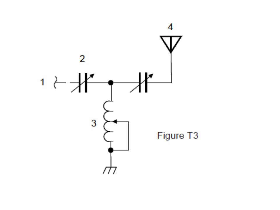
T6C10 What is component 3 in figure T3?
A. Connector B. Meter C. Variable capacitor D. Variable inductor

202
T6C10 What is component 3 in figure T3?
A. Connector B. Meter C. Variable capacitor D. Variable inductor

203
T6C11 What is component 4 in figure T3?
A. Antenna B. Transmitter C. Dummy load D. Ground

205
T6C11 What is component 4 in figure T3?
A. Antenna B. Transmitter C. Dummy load D. Ground

206
T6C12 What do the symbols on an electrical circuit schematic diagram represent?
A. Electrical components B. Logic states C. Digital codes D. Traffic nodes

207
T6C12 What do the symbols on an electrical circuit schematic diagram represent?
A. Electrical components B. Logic states C. Digital codes D. Traffic nodes

208
T6C13 Which of the following is accurately represented in electrical circuit schematic diagrams?
A. Wire lengths B. Physical appearance of components C. The way components are interconnected D. All of these choices are correct

209
T6C13 Which of the following is accurately represented in electrical circuit schematic diagrams?
A. Wire lengths B. Physical appearance of components C. The way components are interconnected D. All of these choices are correct

210
T7A03 Which of the following is used to convert a radio signal from one frequency to another?
A. Phase splitter B. Mixer C. Inverter D. Amplifier

211
T7A03 Which of the following is used to convert a radio signal from one frequency to another?
A. Phase splitter B. Mixer C. Inverter D. Amplifier

212
T7A05 What is the name of a circuit that generates a signal of a desired frequency?
A. Reactance modulator B. Product detector C. Low-pass filter D. Oscillator

213
T7A05 What is the name of a circuit that generates a signal of a desired frequency?
A. Reactance modulator B. Product detector C. Low-pass filter D. Oscillator

214
T7A08 Which of the following describes combining speech with an RF carrier signal?-
A. Impedance matching B. Oscillation C. Modulation D. Low-pass filtering

215
T7A08 Which of the following describes combining speech with an RF carrier signal?-
A. Impedance matching B. Oscillation C. Modulation D. Low-pass filtering

216
T7A01 Which term describes the ability of a receiver to detect the presence of a signal?
A. Linearity B. Sensitivity C. Selectivity D. Total Harmonic Distortion

217
T7A01 Which term describes the ability of a receiver to detect the presence of a signal?
A. Linearity B. Sensitivity C. Selectivity D. Total Harmonic Distortion

218
T7A04 Which term describes the ability of a receiver to discriminate between multiple signals?
A. Discrimination ratio B. Sensitivity C. Selectivity D. Harmonic Distortion

219
T7A04 Which term describes the ability of a receiver to discriminate between multiple signals?
A. Discrimination ratio B. Sensitivity C. Selectivity D. Harmonic Distortion

220
T7A06 What device takes the output of a low-powered 28 MHz SSB exciter and produces a 222 MHz output signal? A. High-pass filter B. Low-pass filter C. Transverter D. Phase converter

221
T7A06 What device takes the output of a low-powered 28 MHz SSB exciter and produces a 222 MHz output signal? A. High-pass filter B. Low-pass filter C. Transverter D. Phase converter

222
T7A13 Which of the following circuits demodulates FM signals?
A. Limiter B. Discriminator C. Product detector D. Phase inverter

223
T7A13 Which of the following circuits demodulates FM signals?
A. Limiter B. Discriminator C. Product detector D. Phase inverter

Similar presentations


![SUBELEMENT T6 [4 Exam Questions - 4 Groups]](/11/3200415/big_thumb.jpg "SUBELEMENT T6 [4 Exam Questions - 4 Groups]>")


![SUBELEMENT T5 [4 Exam Questions - 4 Groups] Electrical Principles, Electronic Principles, Math for Electronics.](/18/6193019/big_thumb.jpg "SUBELEMENT T5 [4 Exam Questions - 4 Groups] Electrical Principles, Electronic Principles, Math for Electronics.>")


![SUBELEMENT T6 [4 Exam Questions - 4 Groups] SUBELEMENT T6 – Electrical Components, semiconductors, circuit diagrams, component functions.](/22/6465513/big_thumb.jpg "SUBELEMENT T6 [4 Exam Questions - 4 Groups] SUBELEMENT T6 – Electrical Components, semiconductors, circuit diagrams, component functions.>")


