Download presentation
Presentation is loading. Please wait.

1
Group -5 Yash Shah, Shreya Bhanushali, Jay Bhavsar, Smit Kotadia,

2
A coupling is a device used to connect two shafts together for the purpose of transmitting power. Two types of couplings Rigid Flexible also known as compensating

3
Couplings interact with other devices by joining two shafts together in order to transmit power from one shaft to another shaft.

4
Rigid couplings are used when precise shaft alignment is required; shaft misalignment will affect the coupling's performance as well as its life.

5
Sleeve or muff or box coupling. Splite muff or clamp coupling. Flange coupling.

6
The coupling consist of sleeve normally made of cast iron in the form of hollw cylinder which recieves end of two shaft made of butt together inside the sleeve. The shaft are secure by means of taoer sunk key extending for the whole length of sleeve. Many a time two separate keys are used to connect shaft ande sleeve. The torque is transmit from shaft to sleeve and then sleeve to shaft.

8
This is a rigid type of coupling and is modification of sleeve coupling. The sleeve is split into apprroximate halves which are connected by two boltswhich are housed in recess formed in the sleeves. The shaft are keyed together by using parellel key in the common key way. This type of couplin is used for heavy duty work.

10
Flanged couplings are a type of rigid coupling that utilizes flanges and bolts to couple to shafts together. Common applications of flanged couplings is joining two pipes together in order to transmit water pressure, it can also be used to extend a rotating shaft.

11
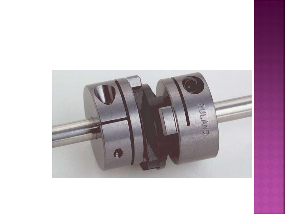
Flexible couplings are designed to transmit torque while permitting some radial, axial, and angular misalignment. Flexible couplings can accommodate angular misalignment up to a few degrees and some parallel misalignment.

12
Universal coupling Oldham coupling Bushed pin type coupling or flange coupling

13
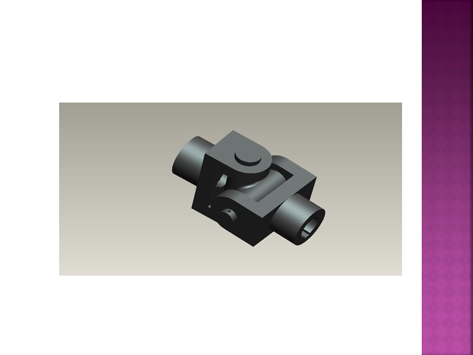
The coupling s used to connect two shaft whose axes will intersect. The angle between the shaft axes may very slightly during operation. The coupling consist of forks keyed to the end of either shaft and they are pin joined to a centre block which has two arms at right angle to Each other. This type of coupling is widely used in automoblie propeller shaft and also in machine tools.

15
Oldham coupling is used in connecting two parellel shaft. The flanges have diametral slots at right angle to each other. The intermiddiate piece a circular disc has diametrel projection on either side at right angle to each othe and closely fit into the slots in the two flanges. The rotation of drive shafts causes the rotation and slinding of circular disc which transmits motion and power to the driven shaft.

17
It is a modified form of protected type flange coupling. The pins are rigidly fastened by nuts to one of the flanges and the enlarge diameter of the pin are converted woth flexible material like leather or rubber bushin. The coupling are commonly used for directly connecting electric motor to a machine. The coupling permits axial movement and takes care of shocks and slides misalignment.

Similar presentations


 Muhammad Ali javaid (47) Muhammad Ali shakir(48) Waqar khan niazi(50)>")


 24 th Oct (Wed) and 31 st Oct (Wed) 11am – 11:55am.>")


 or to the crosshead.>")


 Rigid Coupling B) Flexible Coupling Analysis of Bolts Talking Points.>")
