Download presentation
Presentation is loading. Please wait.

1
Instrument Navigation
Chapter 2, Section C

2
VOR Navigation Ground Based Transmitter 360 Radials
Aligned with magnetic north Directional Line of sight

3
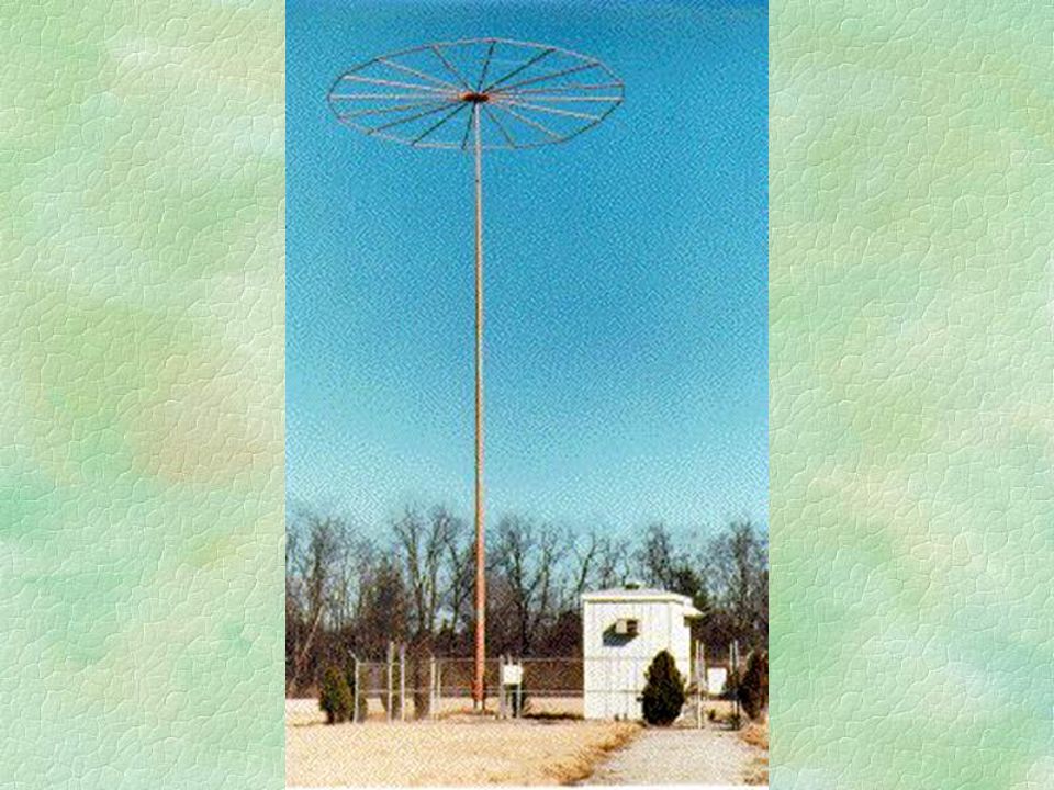
VOR Ground Facility

4
Ground Facilities - VOR
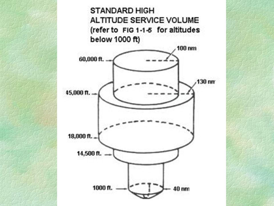
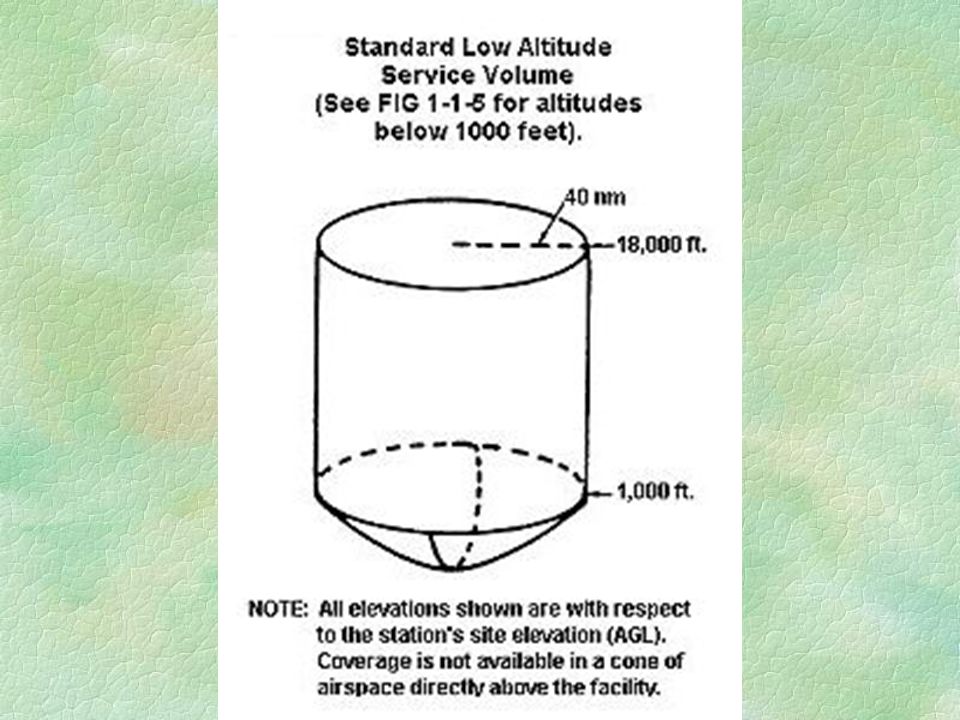
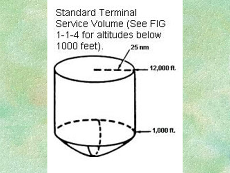
Operate in MHz Band Standard Service Volumes (SSV) High Altitude(HVOR) watts, up to 130 nm, used for airways Low Altitude(LVOR) - about 100 watts, up to 40 nm, used for airways Terminal(TVOR) - 50 watts, 25 nm, used for approaches
 High Altitude(HVOR) watts, up to 130 nm, used for airways. Low Altitude(LVOR) - about 100 watts, up to 40 nm, used for airways. Terminal(TVOR) - 50 watts, 25 nm, used for approaches.")
9
VOR Receiver Checks VOT VOR Ground Checkpoint VOR Airborne Checkpoint
180o TO, 360o FROM; +/- 4o VOR Ground Checkpoint Indicated radial; +/- 4o VOR Airborne Checkpoint Indicated radial; +/- 6o Centerline of airway; +/- 6o Dual VOR Check Within 4o

10
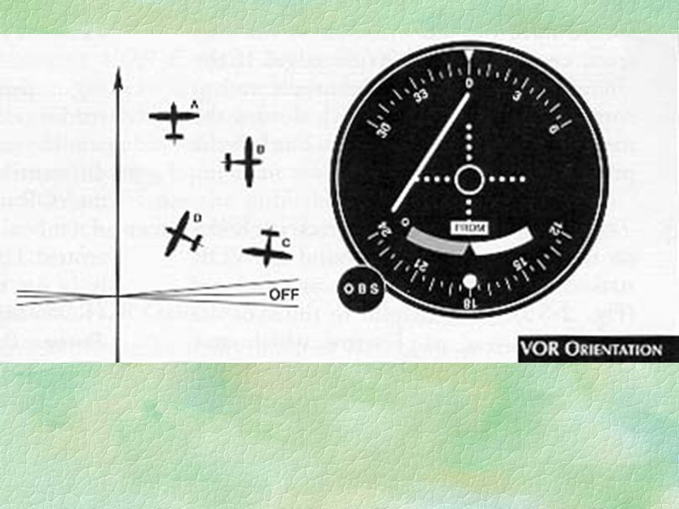
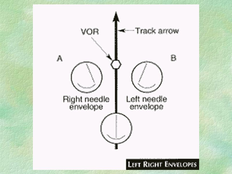
Using the VOR CDI To-From Indicator Intercepting a radial Tracking
wind correction Station passage cone of confusion Reverse sensing
![]()
11
Rotating Course Card TO/FROM Omni Bearing Selector Course Deviation Indicator

14
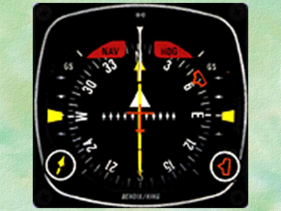
Using the VOR Basic VOR Indicator Horizontal Situation Indicator HSI
each dot on CDI is 2o full scale deflection is 10o 1 deg in 60 nm is 1 nm OBS Horizontal Situation Indicator HSI incorporates HI, CDI, Glideslope makes easier to scan not reverse sensing except for using on BC

16
VOR Time & Distance Calculations
90 deg Method (no wind) Time to station=Time(sec)/bearing change
 Time to station=Time(sec)/bearing change.")
17
VOR Time Distance - 900

18
Time to station (min) Established inbound on a radial rotate the obs 10o to the left, turn the aircraft 10o to the right Note the time and maintain heading until the cdi centers 60 x Min flown between bearing change Degrees of bearing change

19
Distance To station (NM)
TAS X Min. flown between bearing change Degrees of bearing change

20
Isosceles Triangle B 5 minutes 5 minutes C A

21
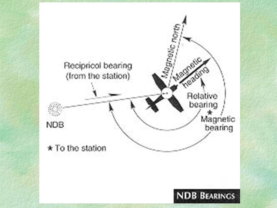
ADF Navigation Ground based transmitter Low/medium frequency (AM)
Non-directional beacon (NDB) Not line of sight No receiver checks No flags - listen to Morse code
 Not line of sight. No receiver checks. No flags - listen to Morse code.")
22
Operational Considerations
NDB Compass locator (LOM) - 25 watts, 15 NM MH - less than 50 watts, 25 NM H - 50 to 1999 watts, up to 50 NM HH - 2,000 watts or more, 75 NM
 - 25 watts, 15 NM. MH - less than 50 watts, 25 NM. H - 50 to 1999 watts, up to 50 NM. HH - 2,000 watts or more, 75 NM.")
24
Using the ADF (fixed card)
Magnetic heading + relative bearing = magnetic bearing Intercepting a bearing Tracking wind correction to the station from the station Time and distance to a station Station passage

25
Rotating Card

28
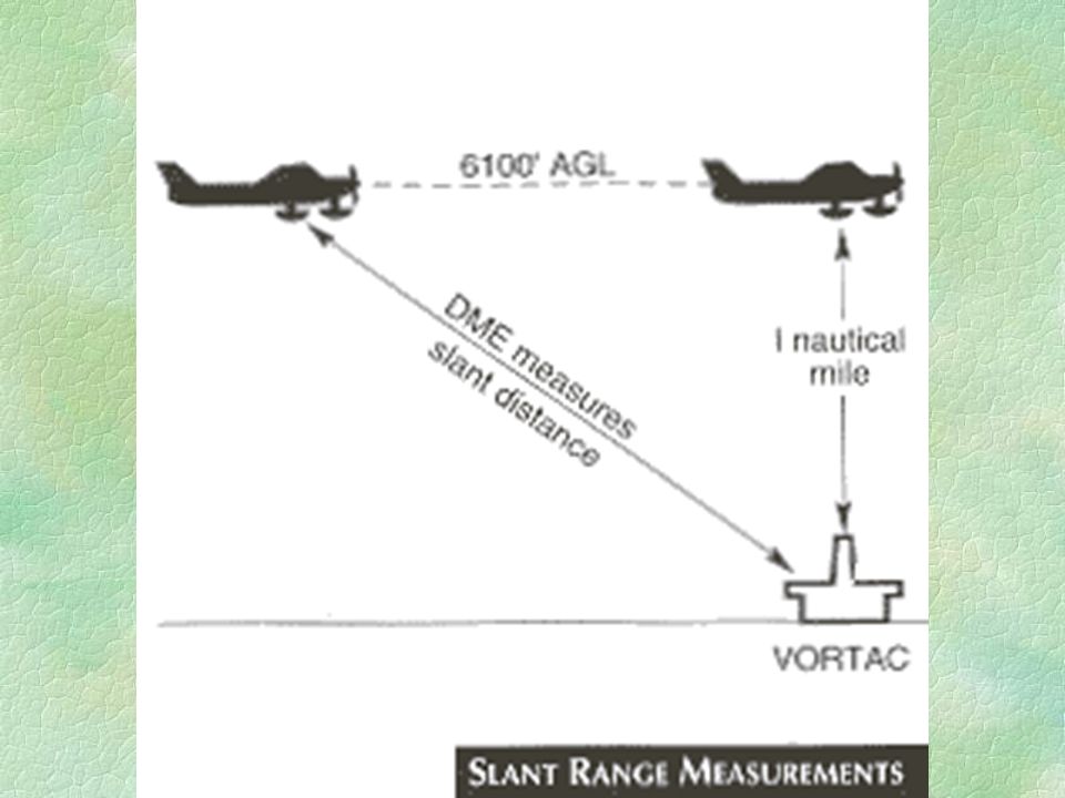
DME Ground based - VOR/DME, VORTAC, ILS/DME, LOC/DME
Interrogation and response rate * time = distance Uses slant distance - 1 NM away for each 1000’ elevation

31
Area Navigation VOR/DME, VORTAC based INS LORAN Phantom VORs
Self Contained LORAN

32
Radio Magnetic Indicator RMI
HI, 1 or 2 pointers for the different stations Pointers show the bearing to the station without mental calculations Tail of the VOR pointer is the radial you are on

34
Global Positioning System(GPS
Describe how it works. A fog horn blows on the hour, … speed of sound is 550 ft/s. Same for GPS except using speed of light. Accuracy within 300 meters 99.99% of time Vertical accuracy is not great. Accuracy can be improved by DGPS

35
Global Positioning System(GPS)
RAIM continuously monitors signals received for validity required for IFR GPS

36
Global Positioning System(GPS)
Two Main types of IFR GPS enroute approved approach approved database must be updated frequently database contains info about airports, intersections, VOR, NDB, etc Lack of Standardization among manufacturers

37
GPS Approaches Generally has a LCD or LED CDI
“fly to the bars” when navigating 30 miles away 1 dot is 1 nm, 5 nm full scale deflection when closer ramps to 1 nm full scale deflection as you fly the approach ramps down to 0.3 nm full scale deflection

Similar presentations


 O-0205 LOCATE A POINT ON A MAP USING THE CAP GRID SYSTEM (S) O-2003 GRID.>")


>")

 Frequency Band : –Airborne: 1025 MHz – 1150 MHz –Ground :63 MHz below Tx frequency 1025 – 1087 MHz 63 MHz above Tx.>")


