Download presentation
Presentation is loading. Please wait.

4
Team Leader : Mr. Khaleel Ahmed Members : Mr. Radhakrishnan V K Mr. Sugmar V Mr. Sourabh Kr. Mishra PROJECT MEMBERS

5
The compound tool project was manufactured as a part of faculty training program on press tool refreshment conducted during the period of January 20 2010 to 10 February 2010. Our project component is a washer having OD 21mm and ID 15.5mm.

6
To manufacture a compound tool The process planning and follow of the project by using macro and micro level process planning Exposure to industrial techniques and manufacturing methods comprising of precision machining like CNC, Wire EDM, Cylindrical Grinding. Knowing the various methods of inspection of the tool parts and components Developing the knowledge about various fits and Tolerance Exposure to tool try out and suggesting further corrections

7
Component name : Washer Operation : blanking and piercing Material : Aluminum Sheet thickness : 1mm Shut height : 115.0mm

8
Piece parts produced from compound tools are very accurate and identical as all operations are carried out in single station. The burr will be formed on the same side. Scrap stocks from other tools can be economically employed to produce pieces parts. The components will have better flatness.

9
In addition to the shedder and the knockout rod, it consists of a knockout plate and transfer pins as shown in the figure. The location and number of transfer pins depend on the size and shape of the blank. INDIRECT KNOCKOUT

10
DIRECT KNOCK OUT. In a knockout system if the knockout rod is directly in contact with the shedder, the system is known as direct knock out system.

11
Shut height is the distances from the bottom of the bottom plate to the top of the plate when the tool is in closed condition. The height of the pillars must be less than the shut height in order to ensure that the ram will not strike against the ends of the pillars. If possible the pillars should be so designed to accommodate the reduction in the shut height, Which will be due to re-sharpening of the punch and die.

12
The die sets consists of a bottom plate and top plate together with guide pillar and bushes. The guide pillars And bushes align the top bottom plates. THE ADVANTAGES OF DIE SETS ARE : Accuracy of set up Improved piece part quality Increased dies life Minimum set up time Easy maintenance Alignment of punch and die

13
Raw materials received Tool assembly drawing and detailed drawing Standard items.

14
Elements manufacturing Stage inspection of all elements Die set assembly Tool assembly Trials – T0,T1,T2 Component inspection

15
The following precision and conventional processes were employed Wire EDM CNC Cylindrical grinding Surface grinding Milling Turning Drilling

16
DETAIL OF ELEMENT MANUFACTURING

17
Pos. no : 02 Quantity : 01 Material : MS Size : 25X100X132 Pre machined and ground Co-ordinate drilling including tooling hole and dowel hole Ø 6H7X2nos Boring of guide bush holes Ø 22H7X2 nos and Ø 28X10mm Deep for transfer plate Completed drilling, tapping, counter boring as per drawing

18
Pos No : 03 Quantity : 01 Material : MS Size : 25X100X132 Pre machined and ground Co-ordinate drilling tooling hole and dowel hole Ø6H7 X 2nos Boring of guide pillar holes Ø15H7 and Ø16H7 and limit screw counter bore Ø17X15mm depth X4nos Completed drilling, tapping, counter boring as per drawing

19
Pos. no : 06 Quantity : 01 Material : MS Size :Ø15/16X100 Pre Turned C.G of Ø15/16g6 for Sliding fit & Ø15/16p6 for Press fit with Bottom Plate

20
Pos. no : 07 Quantity : 02 Material : MS Size :Ø25X50 Pre Turned Reaming of Ø15/16H7 for Sliding fit with Guide Pillar C.G of Ø22p6 for Press fit with Top Plate using mandrel

21
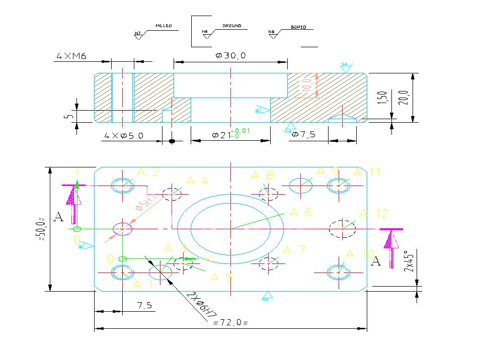
Pos no : 16 Quantity : 01 Material : MS Size : 20X50X72 Pre machined and ground Co-ordinate drilling tooling hole and dowel hole Ø6H7 X 2nos Finishing of counter bore for shedder seating Ø 30 X 10mm depth Wire EDM of Die profile Ø 21.00mm Completed drilling, tapping,as per drawing

23
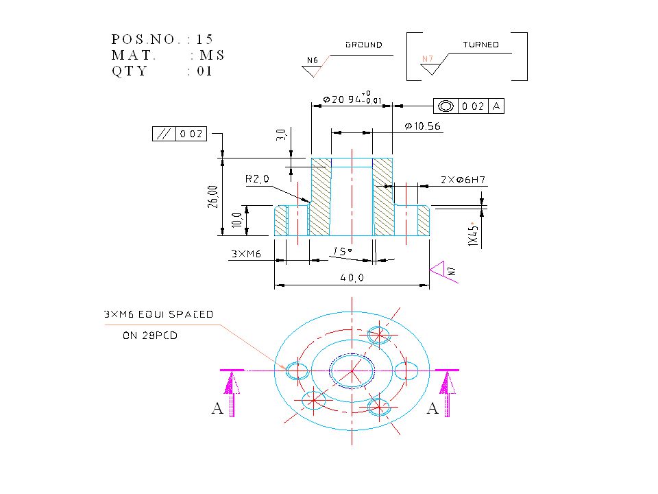
Pos. no : 15 Quantity : 01 Material : MS Size :Ø40X26 Pre machined and ground Co-ordinate drilling & Wire EDM of Ø10.56 C.G of Ø21.00 by using mandral Completed drilling of Screw & Dowel holes as per drawing

25
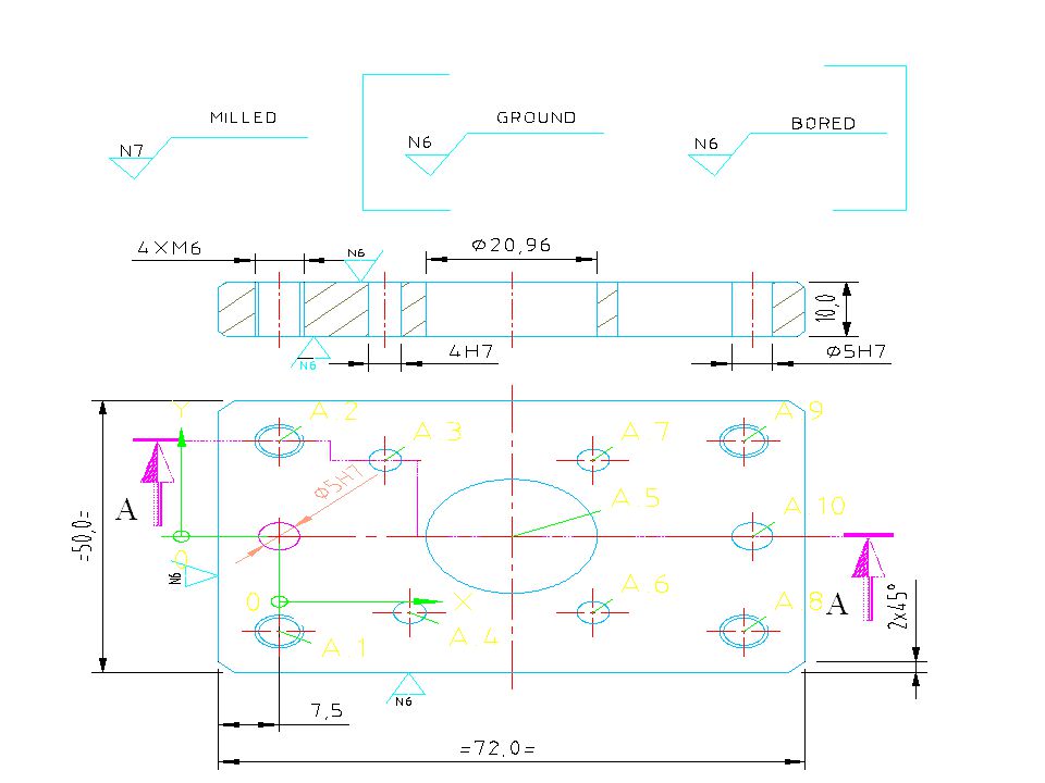
Pos. no : 11 Quantity: 01 Material: MS Size : 10X50X72 Pre machined and ground Co-ordinate drilling tooling hole, strip guide hole Ø4H7 X 4nos and stopper hole Ø 5H7 Wire EDM of Die profile Ø 20.96mm Completed drilling and tapping as per drawing

27
Pos. no : 04 Quantity : 01 Material : MS Size :15X50X72 Pre machined and ground Co-ordinate drilling tooling hole, dowel hole Ø6H7 X 2nos and Ø12H7 for piercing punch Finishing of counter bore Ø16 X 5mm depth for locating piercing punch Completed drilling as per drawing

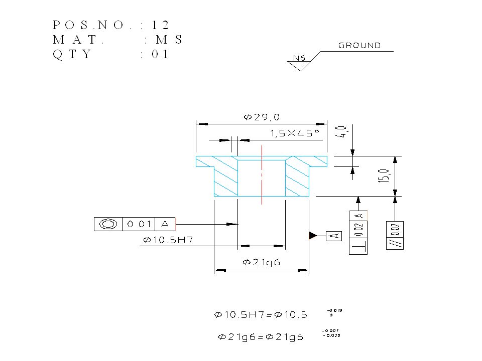
28
Pos. no : 12 Quantity : 01 Material : MS Size :Ø29X15 Pre machined and ground Co-ordinate drilling & Wire EDM of Ø10.5H7 C.G of Ø20.96 by using mandrel

30
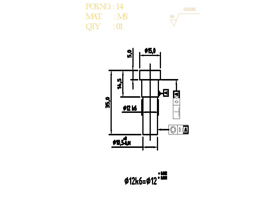
Pos. no : 14 Quantity : 01 Material : MS Size :Ø15X35 Pre Turned C.G of Ø 10.50 for piercing & Ø12k6 for fitment with punch holder

32
Top assembly : At first Die set Assembled, ensured perpendicularity of guide bush with top plate and guide pillar with bottom plate and parallelism also maintained. The piercing punch is fitted to the punch holder with H7/k6 fit head is fleshed in line with the punch holder. The back plate is positioned such that the screw holes and dowel holes are in line with the holes in the punch holder.

33
The shedder is made to slide in the die plate. Piercing punch is made to slide in the shedder (H7 / g6) The shudder is actuated with the help of transfer pin and transfer plate and knock out rod Top plate, punch holder and die plate are clamped with the help of screws and alignment with the help of dowels. Shank is fitted to the top plate
 The shudder is actuated with the help of transfer pin and transfer plate and knock out rod Top plate, punch holder and die plate are clamped with the help of screws and alignment with the help of dowels. Shank is fitted to the top plate.")
34
Bottom assembly : The blanking punch is fitted to the bottom plate with screws and dowels. The strip guide pins and stopper are fixed to the stripper plate. The stripper plate is engaged over the blanking punch with the help of limit bolts. Springs,washers are inserted between stripper and bottom plate for actuating the stripper. Top parallelism of stripper plate is checked after tightening the bolts. The top half and bottom half in closed condiction top parallelism is checked.

35
Die plate : Strip guide pin relief hole made through instead of blind hole. Blanking punch: One dowel hole drilled in wrong position. Shedder: Inside diameter made to diameter 10.56mm instead of diameter 10.5 H7

36
We could able to complete our plan as per macro and micro level planning We achieved Top and Bottom plat co-ordinate drilling as per drawing within Tolerance Die set Assembled properly and it is functioning well All plates coordinate achieved as per drawing with in Tolerance Knockout mechanism functioning as per requirement Traveling stripper functioning as per requirement

37
Importance of macro & micro level process planning Importance of advance tooling manufacturing method Importance of die set assembly Importance of stage & final inspection of tool elements Various method of punch & die alignment Care to be taken while tool trails (check list)
")
38
Team work co-ordination improved. Drawing reading skill improved. Measuring skill & drafting skill improved by dismantling old tools & preparing detail drawings & Assembly. Leadership Quality Priority level by m/c allotment of tool elements Concept of tool fitting elements improved Exposure to C.A.R/ APQP Communication skill improved Concept of allowance for machining operations

39
INDIVIDUAL BENEFIT Mr. Khleel Ahmed Team work Exposure to Macro & Micro level Exposure to APQP Selection of Die materials Preactor software appllications Modular tooling concept Change is every body's business

40
INDIVIDUAL BENEFIT Mr. Radhakrishnana Team work Macro & Micro level APQP Importance Various methods of Tool Manufacturing Selection of Die materials

41
INDIVIDUAL BENEFIT Mr. Sugumar v Team work Macro & Micro level APQP Importance Various methods of Tool Manufacturing Drawing reading Skill improved Machining skill improved Inspection methods improved Concept of SMED and fine blank Tool asembling Techniques improved

42
Leadership skill improved Communication and presentation skill improved. Gained kowledge of various formats and procedure for manufaturing of tools in industries.

43
INDIVIDUAL BENEFIT Mr. Sourabh Kr. Mishra Team work Application & Importance APQP. Application of Macro & Micro level. Latest methods of Tool Manufacturing. Application & Importance about CAR. Learn about various methods & techniques used by Industries. Learn various Soft Skill like Bullet Proof leadership, Team Work. Get Refreshed about Fine Blanking,Trouble Shooting. Tool trouble shooting and corrections of component achieved

44
Mr. N. Dinesh dnnttf@gmail.comdnnttf@gmail.com 09447008766 Mr. Khaleel khaleel5@rediffmail.comkhaleel5@rediffmail.com 09886424399 Mr. Radhakrishna radhakrishna@gmail.comradhakrishna@gmail.com 09449232335 Mr. Promodh promodh14276@yahoo.co.inpromodh14276@yahoo.co.in 09487342657 Mr. Mahesh maheshgnair1@gmail.commaheshgnair1@gmail.com 09846299354 Mr. Sugmar sugupar2006@gmail.comsugupar2006@gmail.com 09778332549 Mr. S.Deenadayla deenavell@gmail.comdeenavell@gmail.com 09786339744 Mr. Sourabh Kr. Mishra sourabhkm.mishra@gmail.com 09973684965

Similar presentations