Download presentation
Presentation is loading. Please wait.

1
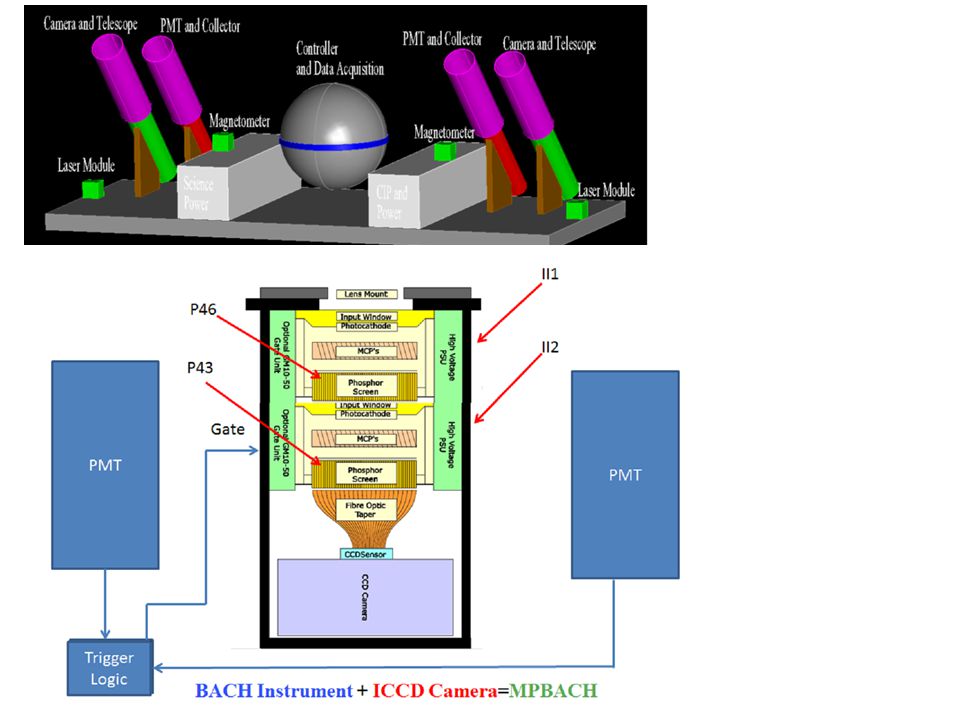
MP BACH MultiPixel Balloon-borne Air CHerenkov Detection of Iron Cosmic Rays Using Direct Cherenkov Radiation Imaged with a High Resolution Camera 1

2
Energy spectrum of Iron cosmic rays multiplied by E 2.5 from different observations. JACEE and RUNJOB, emulsion instruments, are a compilation of many balloon flights. CRN was conducted on the space shuttle. CREAM, ATTC and TRACER are balloon payloads flown from Antarctica and Sweden. BACH payload was flown from Ft Sumner. Sood pioneered the BACH technique. KASKADE (two different interaction models) and EAS-TOP (upper and lower limits) are air shower data. HESS data (two different interaction models) are ground level observations of Cerenkov light imaging. Current knowledge of the iron spectrum
 and EAS-TOP (upper and lower limits) are air shower data. HESS data (two different interaction models) are ground level observations of Cerenkov light imaging. Current knowledge of the iron spectrum.")
3
Integration of the curve in Figure 2 yields a light pool for 35km similar to that shown above. Impact parameter and radius have the same meaning. Light pools are shown for different energies and particle species. The curves are scaled vertically to determine the expected BACH detector response as function of impact parameter. Right: Photo of the BACH payload. Clearly visible are the two 2m long Winston cone light collectors (CAU-1 and CAU-2) and the gondola shell housing the electronics package. The POD (Pressurized Optical Detector) connected to CAU-2 is located inside the large bundle of fiberglass insulation.
 and the gondola shell housing the electronics package. The POD (Pressurized Optical Detector) connected to CAU-2 is located inside the large bundle of fiberglass insulation..")
4
Altitude (km) Distance from Axis (m) 35km 75km 8 -8 0 As the particle penetrates into denser air, the Cherenkov angle and intensity increase. First photons are emitted just on the axis defined by the particle path, but subsequent photons lie further and further from the axis when they reach any given depth in the atmosphere forming a circular spot or “pool” of light. This trend continues until the particle is roughly two scale heights (15 km) above an observer, when proximity finally wins out.
 above an observer, when proximity finally wins out..")
5
Light Pool at 35 km Altitude 5

6
z y x θ φ (x o,y o ) (x 1,0) (x 2,0) θcθc Pathlength to emission point Particle trajectory passes through the x,y plane at location x o,y o The particle incident angle with respect to z is θ and φ is the polar θ c = Cerenkov angle which is a function of z (air density) S is the trajectory straight path-length from the x-y plane intersection to the CK emission point as viewed by camera 1 εc is the CK emission vector as viewed from Camera 1 y x Camera 2Camera 1 z x1x1 No Magnetic Field It can be shown that S is related to the other quantities as S εc
 (x 1,0) (x 2,0) θcθc Pathlength to emission point Particle trajectory passes through the x,y plane at location x o,y o The particle incident angle with respect to z is θ and φ is the polar θ c = Cerenkov angle which is a function of z (air density) S is the trajectory straight path-length from the x-y plane intersection to the CK emission point as viewed by camera 1 εc is the CK emission vector as viewed from Camera 1 y x Camera 2Camera 1 z x1x1 No Magnetic Field It can be shown that S is related to the other quantities as S εc")
7
z y x θ φ (x o,y o ) (x 1,0) (x 2,0) Camera 1 Image Camera 2 Image Example MPBACH Simulated Event Cartoon degrees
 (x 1,0) (x 2,0) Camera 1 Image Camera 2 Image Example MPBACH Simulated Event Cartoon degrees")
8
εc is the CK emission vector as viewed from Camera 1 and 2 z y x θ φ (x o,y o ) (x 1,0) (x 2,0) θ cL Pathlength to emission point S εc b θ cH εc a Intersection of Plane C 1 and C 2 forms a line that lies along the particle trajectory cross product of these two normal C1 and C2 vectors gives a vector which is perpendicular to both of them and which is therefore parallel to the line of intersection of the two planes. So this cross product will give a direction vector for the line of intersection. Set z=0 and solve for x and y With only the DCs, reconstruct trajectory Camera 1 event plane Camera 2 event plane Directional cosine observations from the camera and camera location on the gondola

9
Results The calculated energy uses only the directional cosines, camera location and atmospheric model

10
Deflection in the Earth’s Magnetic Field * Energy & Charge dependence * 10

11
It has been demonstrated the impractically of applying the non-magnetic field solution to finely segmented particle trajectory in a magnetic field such that segments can be assumed to be nearly straight. Combining these straight line segment solution into a global solution is viable, but not practical as this approach is very CPU expensive to achieve adequate accuracy. Consequently a full Lorentzian force equation is applied and fitted to simulated images.

12
CORSIKA Simulations 12 Simulates detailed extensive air showers and generates CK photons QGSJET Hadronic Interaction model

13
Idealized Detector Image Non- Interacting 13

15
Pixilated Camera Image 15

18
Extra slides

19
If the steepening at the cosmic ray knee is caused by a magnetic rigidity dependent mechanism, as a result of an acceleration process limited in a rigidity dependent manner or rigidity dependent propagation, there should be systematic changes in the cosmic ray composition through this region. It is difficult to see how SN could accelerate protons to energies much beyond ~10 15 eV/particle. Heavier cosmic rays, for example iron nuclei, could reach energies over an order of magnitude higher than this via the same mechanism. The objective of this project is to improve our knowledge of the Iron Flux from 5x10 3 to 3x10 6 GeV

20
z y x θ φ (x o,y o ) (x 1,0) (x 2,0) θ cL Pathlength to emission point S εc b θ cH εc a Explicitly determine the relationship for the x,y crossing point at z=0
 (x 1,0) (x 2,0) θ cL Pathlength to emission point S εc b θ cH εc a Explicitly determine the relationship for the x,y crossing point at z=0")
21
Directional cosine observations from the camera and camera location on the gondola The trajectory vector S has been determine and is then used to calculate the Cerenkov angle at each intersection point The index of refraction at each intersection altitude point must be determined to calculate the energy z y x θ φ (x o,y o ) (x 1,0) (x 2,0) θcbθcb Pathlength to emission point S εc b θcaθca εc a
 (x 1,0) (x 2,0) θcbθcb Pathlength to emission point S εc b θcaθca εc a")
22
ThetaC (degrees) Altitude (km)
 Altitude (km)")
Similar presentations


 – Secondaries (pions) – Decay products (muons, photons, electrons)>")


 Origin of cosmic rays.>")
1.493.84 Worst Angular Resolution (deg)2.005.17 Image Surface Area (mm 2 )21302472727.>")


>")