Download presentation
Presentation is loading. Please wait.

1
Flexible AC Transmission System Overview

2
Flexible AC Transmission System
Alternating current transmission systems incorporating power electronics-based and other static controllers to enhance controllability and increase power transfer capability

3
Constraints on Useable Transmission Capacity
Dynamic: Transient and dynamic stability Subsynchronous oscillations Dynamic overvoltages and undervoltages Voltage collapse Frequency collapse

4
Steady-State: Uneven power flow Excess reactive power flows
Voltage capability Thermal capability

5
FACTS Controllers Static VAR Compensator - SVC
Thyristor Controlled Series Compensator - TCSC Thyristor Controlled Phase Angle Regulator - TCPAR Static Synchronous Compensator - StatCom Solid State Series Compensator - SSSC Unified Power Flow Controller - UPFC

6
US FACTS Installations
AEP/ Unified Power Flow Controller /100 MVA/ EPRI NYPA/ Convertible Static Compensator/ 200 MVA Vermont Electric/ STATCOM/ 130 MVA/ Mitsubishi San Diego G&E/ STATCOM/100 MVA Mitsubishi Northeast Utilities/ STATCOM/ 150 MVA/ Areva (Alstom) TVA STATCOM/ 100MVA EPRI Eagle Pass (Texas) Back-to-back HVDC 37 MVA/ ABB Austin Energy STATCOM/ 100MVA ABB CSWS (Texas) STATCOM/ 150 MVA / W-Siemens
 TVA. STATCOM/ 100MVA. EPRI. Eagle Pass (Texas) Back-to-back HVDC. 37 MVA/ ABB. Austin Energy. STATCOM/ 100MVA. ABB. CSWS (Texas) STATCOM/ 150 MVA / W-Siemens.")
7
Power Flow Control Power transfer between areas can be affected by adjusting the net series impedance. Transmission line capability can be increased by installing a series capacitor which reduces the net series impedance.

8
UPFC

9
UPFC may control voltage, impedance, and angle
impacts active and reactive power flow in line

10
Basic Operation

11
UPFC Capabilities Increase transmission line capacity
Direct power flow along selected lines Powerful system oscillation damping Voltage support and regulation Control of active and reactive power flow at both sending- and receiving-end

12
Operation Reactive power is generated or absorbed by the shunt inverter to control bus voltage Reactive power is generated or absorbed by the series inverter to control the real and/or reactive power flow on the transmission line

13
Cont’d A portion of the real power flow on the transmission line is drawn from the bus by the shunt inverter to charge the DC capacitor. Real power is inserted into the line through the series inverter.

14
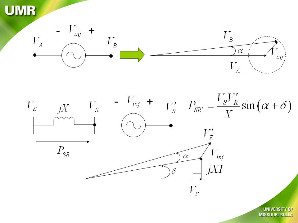
Power flow in a transmission line
and To increase PSR, increase

15
- + - +
16
How is Vinj created? + b1 a2 a1 b2 c1 c2

17
+ + + a1 on, b1 on, c1 off Vab=0, Vbc=V, Vca = -V
a1 on, b1 off, c1 off Vab=V, Vbc=0, Vca = -V a2 b2 c2 + a1 b1 c1 a1 on, b1 off, c1 on Vab=V, Vbc=-V, Vca = 0 a2 b2 c2

18
Sine-triangle PWM

Similar presentations

 Overview and Applications>")
 Huang ERCOT System Planning CIGRE WG B4.62 Meeting June.>")


![Dynamic VAR’s [D-VAR] What are D-VAR Devices? Dynamic VARs… Fully integrated modular STATCOM with proprietary 3X overload Instantaneously injects precise.](/16/5034269/big_thumb.jpg "Dynamic VAR’s [D-VAR] What are D-VAR Devices? Dynamic VARs… Fully integrated modular STATCOM with proprietary 3X overload Instantaneously injects precise.>")


 is a shunt-connected reactive-power compensation device that is capable of generating and/ or absorbing reactive power and.>")
