Download presentation
Presentation is loading. Please wait.

2
Mechanisms of Fuel Combustion P M V Subbarao Professor Mechanical Engineering Department A Basis for Development of Compact SG Systems……

3
Coal Fired Steam Generator System

4
Basic Mechanisms of Solid Fuel Combustion

5
Primitive Method of solid Combustion Primary Air Secondary Air Flame Green Coal Incandescent coke Grate CO+CO 2 +N 2 +H 2 VM+CO+CO 2 +N 2 +H 2 O 2 +CO 2 +N 2 +H 2 O ASH

6
Top-feed updraft combustor

7
Physics of Fixed Bed Combustion A bed of stoker-sized coal particles is supported by a grate. Air flows upwards through the grate and the fuel bed. Upon heating, coal particles first undergo a stage of Thermal preparation. –Evaporation of Moisture drying. –Distillation of VM (Pyrolosis) –Production of enough VM to start ignition. –Combustion of char. The coal flows slowly downward at a velocity V s, as the coal burns out in the lower layer of the bed.
 –Production of enough VM to start ignition. –Combustion of char. The coal flows slowly downward at a velocity V s, as the coal burns out in the lower layer of the bed..")
8
Automation in Fuel Bed Combustion Also called Mechanical Stokers. Travelling Grate Stoker Chain Grate Stoker Spreader Stoker Vibrating Stoker Underfeed Stoker

9
Travelling Grate Stoker Boiler type: natural circulation Firing method: stoker fired Max. continuous rating:9,7 kg/s Steam temperature outlet: 450°C Steam pressure outlet: 4,0 Mpa Gross efficiency: 87% Fuel type: Bituminous coal Net calorific value: 23 MJ/kg

10
SPREADER-STOKER FIRED BOILER

11
Solid fuel- fired boiler system

12
Typical Size Distribution Coal for Stoker Furnace

13
Closing Remarks on Grate Firing The first limit on grate firing is that of scale. A practical engineering limit seems to be reached when the length and width of the grate are about 9 m with grate area 80 m 2. At 2 MW/m 2, the steam capacity at 85% efficiency would be 150 MW or 270 tons per hour. In practice stokers have rarely exceeded a capacity of 135 tons/hour. The limitation is partly grate area and partly firing density. The limitation on firing density exist due to: The rate of movement of the reaction plane could not match the opposed rate of fuel flow leading to blow-off. The experience with grate combustion led to development of many requirements for further development.

14
Parameters for Combustion Requirements Heat Release Rate Volumetric Combustion Intensity Area Combustion Intensity Effective Reactor Height Coal Firing Density Area Firing Density Products of combustion Velocity Air Velocity Combustion time Particle Heating Rate Heat Transfer Fluxes Heat exchange surface area per unit cross sectional area of combustion chamber,

15
Heat Release Rate : A Capacity Limit Most common Grate fired furnace ~ 30 MW. Maximum obtained ~ 150 MW. Maximum Power Generation Capacity ~ 50 MW Future Projected Requirement ~ 3000 MW

16
Firing Densities Limits : An Optimal Choice Firing densities are expressed in two ways: A volumetric combustion intensity, I v. High value of I v : Compact furnace Low Capital cost Less time for combustion Low Values of I v Bulky furnace More time for combustion Low Running Cost Area Firing Intensity, I A High value of I A Sleek furnace Higher combustion Temperatures Better Ignition Low Value of I A Poor Ignition Fat furnace Low No x Solid Ash

17
Pulverized Fuel Combustion Invented in 1920. An universal choice for power plants till 1990. Fine particles of coal ~ 75 microns. Surface area : 150 m 2 /kg. Huge heat release per unit area : 2 – 5 MW/m 2. Steam generation : 2000 tons/hour.

18
Fluid Mechanics of Solid Beds pp Velocity Static Bed Dynamic Bed Floating Bed

20
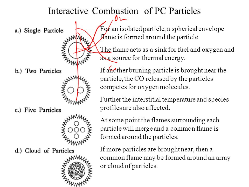
Interactive Combustion of PC Particles For an isolated particle, a spherical envelope flame is formed around the particle. The flame acts as a sink for fuel and oxygen and as a source for thermal energy. If another burning particle is brought near the particle, the CO released by the particles competes for oxygen molecules. Further the interstitial temperature and species profiles are also affected. At some point the flames surrounding each particle will merge and a common flame is formed around the particles. If more particles are brought near, then a common flame may be formed around an array or cloud of particles.

Similar presentations