Download presentation
Presentation is loading. Please wait.

1
Laurent Tavian Thanks to contribution and helpful discussions with M. Jimenez, V. Parma, F. Bertinelli, J.Ph. Tock, R. van weelderen, S. Claudet, A. Perin, C. Garion, R. Schmidt

2
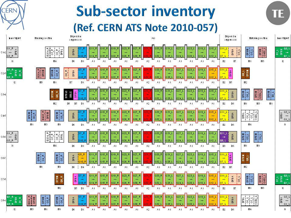
Introduction – Recall of the 19 th Sept’08 fault tree – Recall of sector consolidation status for 2011/12 operation Updated fault trees and consequences in case of: – A hypothetical electrical arc in a cryo-magnet interconnect for beam energy up to 5 TeV – A hypothetical electrical arc in a magnet cold-mass for beam energy up to 5 TeV Conclusion

3
Electrical arc Beam pipe perforation He vessel perforationSoot He discharge in insulation vacuum Contamination by sootInadequate sizing of relief devices (MCI) Pressurization of vacuum enclosures Mechanical damage to MLI Contamination by MLI ODH in tunnelBlast Trip AUG Loss of beam vacuum Break vent door Ph. Lebrun

4
Pressurization of vacuum enclosures Pressure forces on vacuum barriers Plastic deformation of shellsBuckling of bellows Rupture of supports and ground anchors Displacement of magnets Mechanical damage to interconnects Secondary electrical arcs Damage to tunnel floor Ph. Lebrun

6
080919 accident (~ 5 TeV) With “smaller” electrical arc (i.e. lower magnetic stored energy and/or lower discharge time constant), perforation of the beam pipe can not be excluded with the present consolidation status. (Electrical insulation of the beam pipe interconnect foreseen in 2013/12)
, perforation of the beam pipe can not be excluded with the present consolidation status. (Electrical insulation of the beam pipe interconnect foreseen in 2013/12).")
7
Mass flow MCI flow (already at 3.5 TeV, an electrical arc is able to create the MCI breaches ( 2 x 60 cm 2 )), e.g. 30 kg/s in the continuous cryostat. Temperature of helium heated by the electrical arc power and discharged through the safety devices depends on: the stored magnetic energy The current discharge time constant The heat transferred by convection from the environment.

9
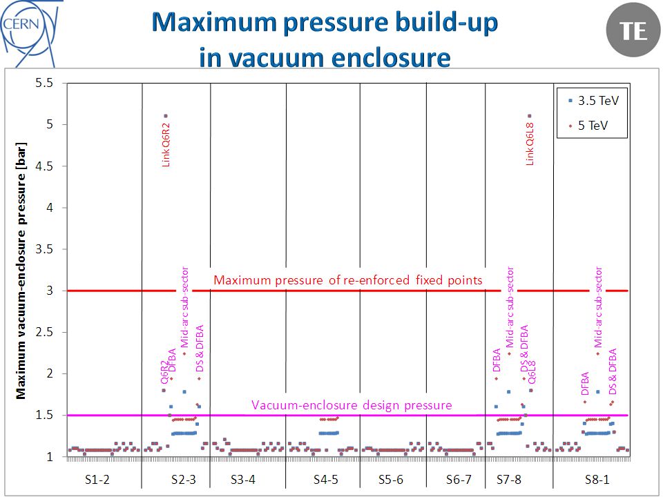
Vacuum sub-sector P max [bar] Remarks 3.5 TeV5 TeV Link Q6R2 & Q6L8 5.1 Compatible with vacuum enclosure design margin (DN200 link) Q6R2 & Q6L8 1.8 Compatible with vacuum enclosure design margin Mid-arc S2-3, S7-8 & S8-1 1.82.3* Compatible with vacuum enclosure design margin and re-enforced fixed points on SSS DFBA HCM R2, L3, R7 & L8 1.62.0 Compatible with vacuum enclosure design margin and re-enforced fixed points on DFBA DFBA HCM R8 & L1 1.41.7 Compatible with vacuum enclosure design margin and re-enforced fixed points on DFBA DS L3, L8 & L1 1.41.6 Compatible with vacuum enclosure design margin and re-enforced fixed points on SSS and DFBA Conclusion: Up to 5 TeV, no longer mechanical collateral damages in adjacent sub-sectors! *: Above 1.9 bar, plastic deformation of SSS vacuum barrier could occur (pressure test under preparation)
![Vacuum sub-sector P max [bar] Remarks 3.5 TeV5 TeV Link Q6R2 & Q6L8 5.1 Compatible with vacuum enclosure design margin (DN200 link) Q6R2 & Q6L8 1.8 Compatible with vacuum enclosure design margin Mid-arc S2-3, S7-8 & S * Compatible with vacuum enclosure design margin and re-enforced fixed points on SSS DFBA HCM R2, L3, R7 & L Compatible with vacuum enclosure design margin and re-enforced fixed points on DFBA DFBA HCM R8 & L Compatible with vacuum enclosure design margin and re-enforced fixed points on DFBA DS L3, L8 & L Compatible with vacuum enclosure design margin and re-enforced fixed points on SSS and DFBA Conclusion: Up to 5 TeV, no longer mechanical collateral damages in adjacent sub-sectors.](http://images.slideplayer.com/20/6008722/slides/slide_9.jpg "*: Above 1.9 bar, plastic deformation of SSS vacuum barrier could occur (pressure test under preparation).")
10
Electrical arc Beam pipe perforation He vessel perforationSoot He discharge in insulation vacuum Contamination by sootInadequate sizing of relief devices (MCI) Pressurization of vacuum enclosures Mechanical damage to MLI Contamination by MLI ODH in tunnelBlast Trip AUG Loss of beam vacuum Break vent door Ph. Lebrun Instrumentation flange opening on temporary consolidated sectors Mechanical damage of instrumentation cabling

11
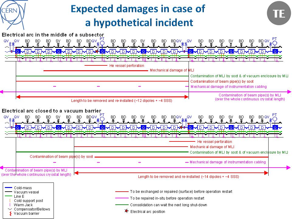
Sept’08 damages which are mitigated by the 2009 consolidations: – Plastic deformation of shells – Buckling of bellows – Rupture of supports and ground anchors – Damage to tunnel floor – Mechanical damage to interconnects – Secondary electrical arcs Damages still present up to 5 TeV – He vessel and beam pipe perforation – Mechanical damage of MLI – Contamination by soot of MLI and beam pipes – Contamination by MLI of vacuum enclosure and beam pipes – Mechanical damage of BPM cabling

13
Without MLI, cold mass enclosure are not protected against pressure build-up in case of break of the insulation vacuum with air. Not compatible with the cold-mass pressure relief system ! Ph. Lebrun

14
S3-4 incident: ~ 2/3 of the total affected length (22 cryo- magnets over 2 sub-sectors) New incident ?: – MLI damage goes with v 2 or m 2 / or m 2 T/P S3-4 incident 30 kg/s – 6 bar – 70 K New incident 3.5 TeV: 30 kg/s – 1.1 to 1.3 bar – 40 K factor 3 to 2.6 New incident 5 TeV: 30 kg/s – 1.1 to 1.5 bar – 60 K factor 4.5 to 3.5 – But the distribution of the safety devices allows a faster decrease of the flow along the length – Let’s assume the same damage ratio (2/3) for a new incident i.e.: ~ 10/16 cryo-magnets to be repaired use of spares for dipoles re-cryostating of SSS (no spare) – Question: Can we safely operate with only missing MLI on SSS? (if yes, the heavy SSS re-cryostating could wait the next long shutdown!)
.")
15
Experience return from S3-4 – V1 more representative (not burst disk opening) – In V1 about 600 m contaminated with soot – Pressurization: up to 3.5 bar V1 V2 ~600 m ~400 m New incident expectation: Affected length is assumed to be proportional to the quantity of soot introduced: For most sub-sectors, pressurization limited to 1.1-1.5 bar: quantity of soot introduced in the beam pipes divided by 2.3 to 3 250 to 200 m of magnet could be affected For the specific mid-arc subsectors (3/8), pressurization limited to 1.8 -2.3 bar: quantity of soot introduced in the beam pipe divided by 2 to 1.5 300 to 400 m of magnet could be affected M. Jimenez

16
Remark: In case of a hypothetical electrical arc in an Inner Triplet, soot contamination of the detector beam pipe cannot be excluded (Fast shutter valves installation only in 2013/12 long shutdown) Long and heavy repair work if NEG coatings are damaged! (4 to 6 months)
.")
17
Electrical arc in a magnet cold mass Beam pipe perforation Magnet quenchSoot ?* Pressurization of CM Contamination by soot ?* ODH in tunnel Pressurization of beam vacuum Beam pipe rupture disk opening Mechanical damage of bellows (Nested & PIMs) *Not seen during the “Noell 4” Incident in SM18
 *Not seen during the Noell 4 Incident in SM18")
18
Nested bellows buckling PIM bellows buckling C. Garion

19
Nested bellows buckling PIM bellows buckling Working line ? KC. Wu R. van Weelderen S. Claudet

20
Beam pipe perforation of a single magnet (Reminder: the downtime for a single dipole exchange is about 4 months) Plastic deformation (rupture ?) of nested & PIM bellows: – No damage at 3.5 TeV (with 50 s time constant) – Could become critical above 3.5 TeV especially if we increase the discharge time constant. PIMs can be repaired in-situ Nested bellow repair requires magnet removal.

21
Electrical arc in an interconnect: – The present consolidation, up to 5 TeV, will suppress mechanical collateral damages in adjacent sub-sectors. – Nevertheless, mechanical damage of the MLI in the concerned sub- sector as well as contamination of the beam pipe(s) could require heavy repair work. – With the present consolidation status, a new incident will still have big impact on the machine down time (8 to 12 months) Electrical arc in a dipole coil: – Limited impact at 3.5 TeV (but at least 4 months of downtime to exchange one dipole) – Could be more critical above 3.5 TeV (damage of bellows over several sub-sectors) A hypothetical incident caused by an electrical arc during the 2011/12 operation could seriously impact the LHC physics program: Corresponding risks must be carefully assessed.
 could require heavy repair work. – With the present consolidation status, a new incident will still have big impact on the machine down time (8 to 12 months) Electrical arc in a dipole coil: – Limited impact at 3.5 TeV (but at least 4 months of downtime to exchange one dipole) – Could be more critical above 3.5 TeV (damage of bellows over several sub-sectors) A hypothetical incident caused by an electrical arc during the 2011/12 operation could seriously impact the LHC physics program: Corresponding risks must be carefully assessed..")
Similar presentations

, Katy Foraz (coordinates all the activities), Antonio Foreste,>")


 is co-funded by the European Commission within the Framework Programme 7 Capacities Specific Programme,>")


 is co-funded by the European Commission within the Framework Programme 7 Capacities Specific Programme,>")


