Download presentation
Presentation is loading. Please wait.

1
Interfaces A practical approach. Lesson 2 I2C and SPI
2
Hardware description

3
PIC18F2580 board

4
PIC18F2580 board schematics

5
PIC18F2580 board connector

6
SPI Serial Peripheral Interface Bus
Devices communicate in master/slave mode where the master device initiates the data frame.

7
SPI Serial Peripheral Interface Bus 2
The SPI bus specifies four logic signals: SCLK: Serial Clock (output from master); MOSI; SIMO: Master Output, Slave Input (output from master); MISO; SOMI: Master Input, Slave Output (output from slave); SS: Slave Select (active low, output from master).
; MOSI; SIMO: Master Output, Slave Input (output from master); MISO; SOMI: Master Input, Slave Output (output from slave); SS: Slave Select (active low, output from master)")
8
SPI Serial Peripheral Interface Bus 3
Advantages Full duplex communication Higher throughput than I²C or SMBus Complete protocol flexibility for the bits transferred Not limited to 8-bit words Arbitrary choice of message size, content, and purpose Extremely simple hardware interfacing Typically lower power requirements than I²C or SMBus due to less circuitry (including pullups) No arbitration or associated failure modes Slaves use the master's clock, and don't need precision oscillators Slaves don't need a unique address -- unlike I²C or GPIB or SCSI Transceivers are not needed
 No arbitration or associated failure modes. Slaves use the master s clock, and don t need precision oscillators. Slaves don t need a unique address -- unlike I²C or GPIB or SCSI. Transceivers are not needed")
9
SPI Serial Peripheral Interface Bus 3
Disadvantages Requires more pins on IC packages than I²C, even in the "3-Wire" variant No in-band addressing; out-of-band chip select signals are required on shared buses No hardware flow control by the slave (but the master can delay the next clock edge to slow the transfer rate) No hardware slave acknowledgment (the master could be "talking" to nothing and not know it) Supports only one master device No error-checking protocol is defined Generally prone to noise spikes causing faulty communication Without a formal standard, validating conformance is not possible Only handles short distances compared to RS-232, RS-485, or CAN-bus
 No hardware slave acknowledgment (the master could be talking to nothing and not know it) Supports only one master device. No error-checking protocol is defined. Generally prone to noise spikes causing faulty communication. Without a formal standard, validating conformance is not possible. Only handles short distances compared to RS-232, RS-485, or CAN-bus")
10
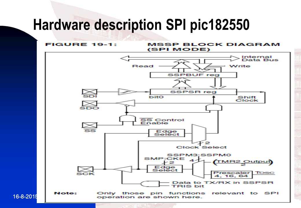
Hardware description SPI pic182550
11
MASTER SYNCHRONOUS SERIAL PORT (MSSP) SPI and I2C
• Serial Peripheral Interface (SPI) • Inter-Integrated Circuit (I2C™) - Full Master mode - Slave mode (with general address call) The I2C interface supports the following modes in hardware: • Master mode • Multi-Master mode • Slave mode
 • Inter-Integrated Circuit (I2C™) - Full Master mode. - Slave mode (with general address call) The I2C interface supports the following modes in hardware: • Master mode. • Multi-Master mode. • Slave mode")
12
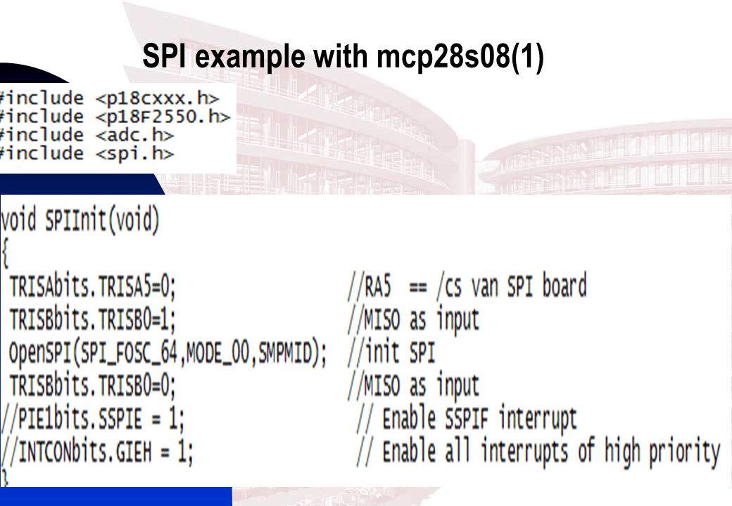
SPI example with mcp28s08(1)
13
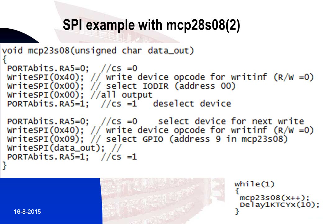
SPI example with mcp28s08(2)
14
Pic18f2580 SPI/I2C • Serial Data Out (SDO) – RC5/SDO
• Serial Data In (SDI) – RC4/SDI/SDA • Serial Clock (SCK) – RC3//SCK/SCL Additionally, a fourth pin may be used when in a Slave mode of operation: • Slave Select (SS) – RA5/AN4/SS/
 – RC4/SDI/SDA. • Serial Clock (SCK) – RC3//SCK/SCL. Additionally, a fourth pin may be used when in a Slave mode of operation: • Slave Select (SS) – RA5/AN4/SS/")
15
Inter-Intergrated circuit. I2C
Two-wire interface Philips 1990’s Opend Drain signals SDA SCL +5V or 3.3 V 7 bits address -16 reserved = 112 nodes possible 10 kbits/s 100kbits/s 400 kbits/s 3.4Mbits/s

16
I2C Protocoll overheads Rp pull up for open drain. SDA SCL
Maximum bus capacitance 400 pF Protocoll overheads -slave address -sometimes registeraddress -ACK/NACK bits

17
I2C –bus protocol

18
I2C example MCP23008

19
I2C example MCP23008

20
I2C example MCP23008 init

21
I2C example MCP23008 data out

22
I2C example use of MCP23008

Similar presentations


>")


>")


 which allows communication between multiple integrated circuits.>")


