Download presentation
Presentation is loading. Please wait.

1
Chapter 9 Counters

2
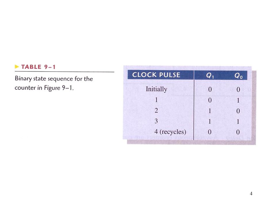
Figure 9--1 A 2-bit asynchronous binary counter.
Asynchronous Counter Operation Figure A 2-bit asynchronous binary counter.

3
Figure 9--2 Timing diagram for the counter of Figure 9-1
Figure Timing diagram for the counter of Figure 9-1. As in previous chapters, output waveforms are shown in green.

6
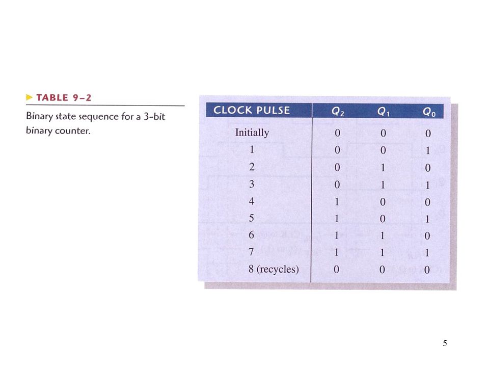
Figure 9--3 Three-bit asynchronous binary counter and its timing diagram for one cycle.

7
Figure 9--4 Propagation delays in a 3-bit asynchronous (ripple-clocked) binary counter.
 binary counter.")
8
Figure 9--5 Four-bit asynchronous binary counter and its timing diagram.

9
Figure 9--6 An asynchronously clocked decade counter with asynchronous recycling.

10
Figure 9--7 Asynchronously clocked modulus-12 counter with asynchronous recycling.

11
Figure The 74LS93A 4-bit asynchronous binary counter logic diagram. (Pin numbers are in parentheses, and all J and K inputs are internally connected HIGH.)
.")
12
Figure 9--9 Two configurations of the 74LS93A asynchronous counter
Figure Two configurations of the 74LS93A asynchronous counter. (The qualifying label, CTR DIV n, indicates a counter with n states.)
")
13
Figure 9--10 74LS93A connected as a modulus-12 counter.

14
Figure 9--11 A 2-bit synchronous binary counter.
Synchronous Counter Operation Figure A 2-bit synchronous binary counter.

15
Figure Timing details for the 2-bit synchronous counter operation (the propagation delays of both flip-flops are assumed to be equal).
.")
16
Figure 9--13 Timing diagram for the counter of Figure 9-11.

17
Figure 9--14 A 3-bit synchronous binary counter.

18
Figure 9--15 Timing diagram for the counter of Figure 9-14.

20
Figure 9--16 A 4-bit synchronous binary counter and timing diagram
Figure A 4-bit synchronous binary counter and timing diagram. Points where the AND gate outputs are HIGH are indicated by the shaded areas.

21
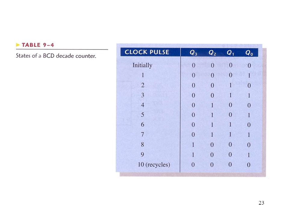
Figure 9--17 A synchronous BCD decade counter.

22
Figure 9--18 Timing diagram for the BCD decade counter (Q0 is the LSB).
.")
24
Up/Down Synchronous Counter

25
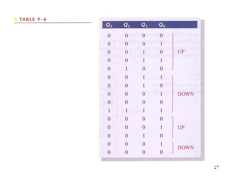
Figure 9--23 A basic 3-bit up/down synchronous counter.

26
Figure 9—24 : Example 9-4 - Timing Diagram

28
Figure 9--27 General clocked sequential circuit.
Design of Synchronous Counters Figure General clocked sequential circuit.

29
Figure 9--28 State diagram for a 3-bit Gray code counter.
Step 1: State Diagram Figure State diagram for a 3-bit Gray code counter.

30
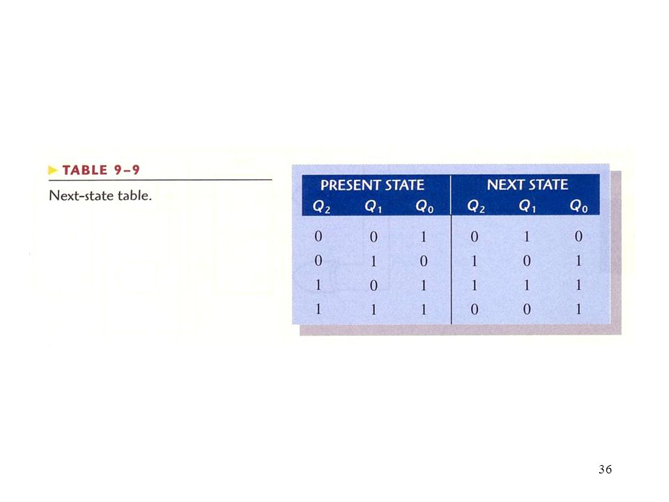
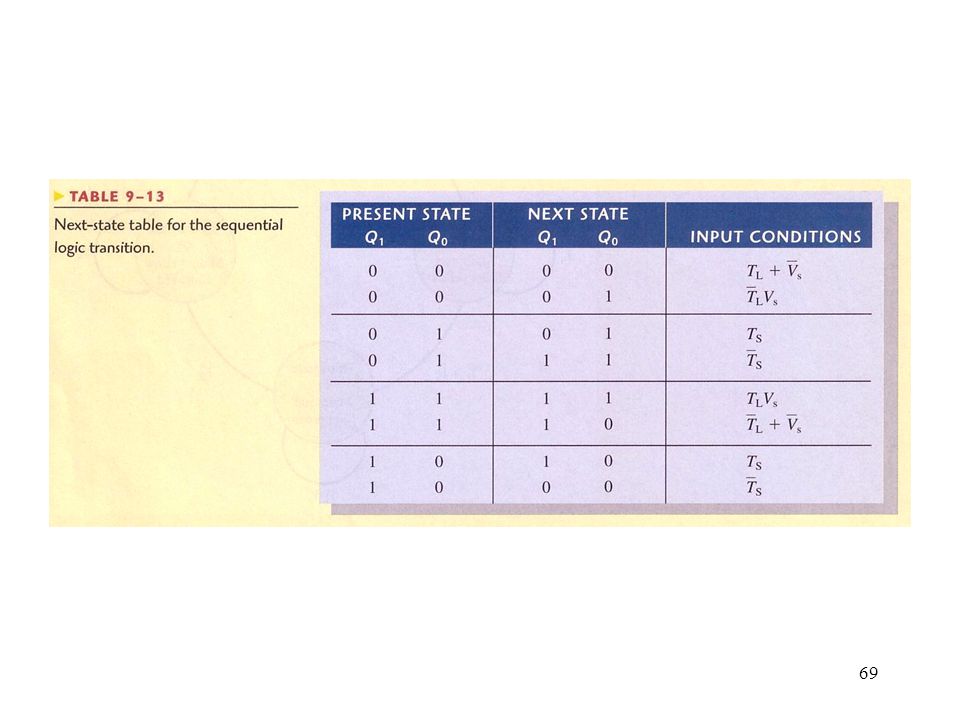
Step 2: Next-State Table

31
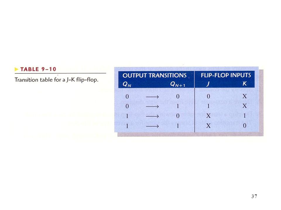
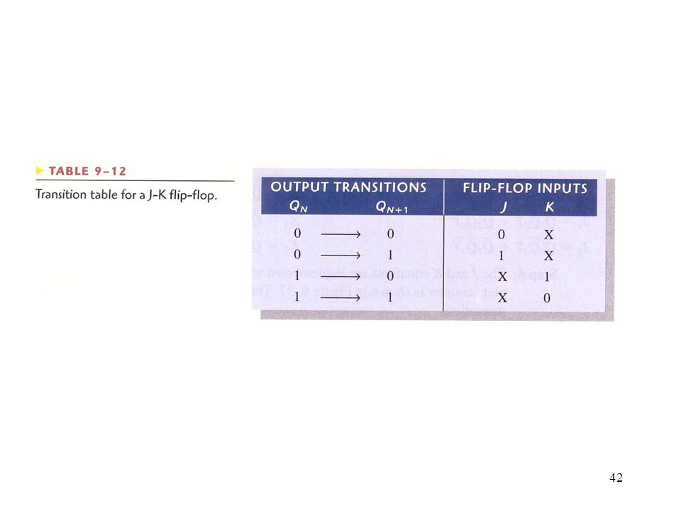
Step 3: Flip-Flop Transition Table

32
Step 4: Karnaugh Maps Figure Examples of the mapping procedure for the counter sequence represented in Table 9-7 and Table 9-8.

33
Figure 9--30 Karnaugh maps for present-state J and K inputs.
Step 5: Logic Expressions for Flip-Flop Inputs Figure Karnaugh maps for present-state J and K inputs.

34
Figure 9--31 Three-bit Gray code counter.
Step 6: Counter Implementation Figure Three-bit Gray code counter.

35
Figure 9—32 : Example 9-5

38
Figure 9--33

39
Figure 9--34

40
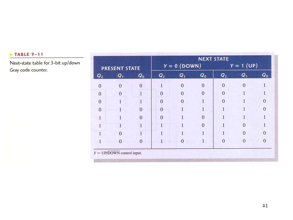
Figure 9--35 Example 9-6 - State diagram for a 3-bit up/down Gray code counter.

43
Figure 9--36 J and K maps for Table 9-11
Figure J and K maps for Table The UP/DOWN control input, Y, is treated as a fourth variable.

44
Figure 9--37 Three-bit up/down Gray code counter.

45
Figure 9--38 Two cascaded counters (all J and K inputs are HIGH).
.")
46
Figure 9--39 Timing diagram for the cascaded counter configuration of Figure 9-38.

47
Figure 9--40 A modulus-100 counter using two cascaded decade counters.

48
Figure Three cascaded decade counters forming a divide-by-1000 frequency divider with intermediate divide- by-10 and divide-by-100 outputs.

49
Figure 9—42 : Example 9-7 – Determine the overall modulus

50
Figure 9--43 A divide-by-100 counter using two 74LS160 decade counters.

51
Figure A divide-by-40,000 counter using 74HC161 4-bit binary counters. Note that each of the parallel data inputs is shown in binary order (the right-most bit D0 is the LSB in each counter).
..")
52
Figure 9--45 Decoding of state 6 (110).
Counter Decoding Figure Decoding of state 6 (110).
.")
53
Figure 9--46 : Example 9-9 - A 3-bit counter with active-HIGH decoding of count 2 and count 7.

54
Figure 9--47 A basic decade (BCD) counter and decoder.
 counter and decoder.")
55
Figure 9--48 Outputs with glitches from the decoder in Figure 9-47
Figure Outputs with glitches from the decoder in Figure Glitch widths are exaggerated for illustration and are usually only a few nanoseconds wide.

56
Figure 9--49 The basic decade counter and decoder with strobing to eliminate glitches.

57
Figure 9--50 Strobed decoder outputs for the circuit of Figure 9-49.

58
Counter Applications : Digital Clock
Figure Simplified logic diagram for a 12-hour digital clock. Logic details using specific devices are shown in Figures 9-52 and 9-53.

59
Figure Logic diagram of typical divide-by-60 counter using 74LS160A synchronous decade counters. Note that the outputs are in binary order (the right-most bit is the LSB).
..")
60
Figure 9--53 Logic diagram for hours counter and decoders
Figure Logic diagram for hours counter and decoders. Note that on the counter inputs and outputs, the right-most bit is the LSB.

61
Figure 9--54 Functional block diagram for parking garage control.
Counter Applications : Automobile Parking Control Figure Functional block diagram for parking garage control.

62
Figure 9--55 Logic diagram for modulus-100 up/down counter for automobile parking control.

63
Figure 9--56 Parallel-to-serial data conversion logic.
Counter Applications : Parallel-to-Serial Data Conversion (Multiplexing) Figure Parallel-to-serial data conversion logic.
 Figure Parallel-to-serial data conversion logic.")
64
Figure 9--57 Example of parallel-to-serial conversion timing for the circuit in Figure 9-56.

65
Application Figure Traffic light control system block diagram and light sequence.

66
Figure 9--67 Block diagram of the sequential logic.

67
Figure 9--68 State diagram showing the 2-bit Gray code sequence.

68
Figure 9--69 Sequential logic.

72
Figure 9--70

73
Figure 9--71

74
Figure 9--72

Similar presentations


 Shift Registers and Application Counters (Types,>")
 latches S-R (Set-Reset) Latch.>")

 latches>")


 in addition to its current inputs The state of the circuit is.>")


