Download presentation
Presentation is loading. Please wait.

1
Fuel System Fundamentals
Chapter 40

2
Objectives Explain the operation of the various carburetor systems
Compare fuel injection to carburetion Identify the different types of fuel injection Describe the design and function of electronic fuel injection components Understand how a computer feedback system works

3
Introduction Fuel systems
Must deliver proper mixture of air and fuel to be burned efficiently Must store enough fuel so the car can complete a trip of a few hundred miles This chapter provides an overview of operation, uses, and advantages of different fuel systems

4
Fuel System Fuel delivery system components Fuel induction system
Storage tank Pump Pressure regulator Filters Fuel lines Hoses Fuel induction system Provides correct mixture of burnable air-fuel mixture

5
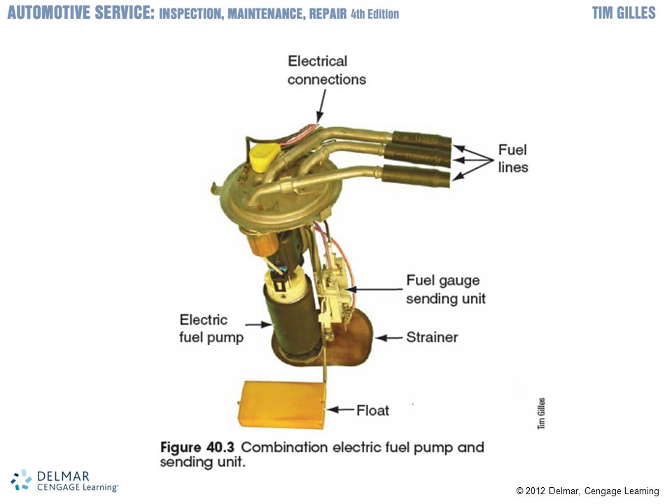
Fuel Tanks Fuel tanks: hold 12-20 gallons
Corrosive-resistant galvanized steel or plastic Baffle prevents fuel sloshing in tank Fuel pickup tube is installed through a hole in bottom of tank Cluster assembly includes pickup tube, fuel gauge, fuel pump In-tank filter is installed at end of pickup tube Tank has expansion and overfill protection

7
Fuel Lines, Hoses, and Fittings
Steel lines made of seamless tubing Run the length of the frame Transport fuel from tank to engine Hoses Used for flexible connections

8
Fuel Pumps Fuel from pump flows in a fuel rail loop between engine and fuel tank Pressure regulator controls system pressure Electric fuel pump has one-way check valve that maintains pressure when engine is off Submerged in well of fuel so cannot spark Fuel pump electrical circuit Electric fuel pumps on modern vehicles: computer controlled Remain on when engine is cranking or running

9
Fuel Filters Located in fuel line or tank Fuel injection systems
Outlet filters: installed on outlet side of fuel pump Fuel injection systems Require large, heavy-duty filters Filter out smaller particles of dirt while allowing pump to supply fuel

10
Fuel Injection and Carburetion
Atomization: fuel suspended in air in tiny drops Vaporization: atomized fuel turns into gas Modern vehicles use fuel injections Older vehicles use carburetors Atomize air and fuel Mounted on top of intake manifold Venturi restricts airflow Fuel is drawn into stream of air flowing through the carburetor

12
Fuel Injection and Carburetion (cont'd.)
Airflow is changed by opening the throttle plate Butterfly valve in bottom of carburetor Opens when accelerator depressed Float circuit: works as a toilet does Main jet: provides opening to meter fuel amount Idle port: allows a small amount of air and fuel to be metered into the intake manifold Accelerator pump: provides extra fuel when car is accelerated quickly Power valve: allows extra fuel to bypass main jet Choke: restricts incoming air

14
Fuel Injection and Carburetion (cont'd.)
Feedback carburetors Meter fuel according to how much oxygen is sensed by an oxygen sensor in engine’s exhaust Fuel injection operation Fuel injection provides a better means of controlling exhaust emissions and fuel economy Fuel injection system designs Many types

15
Fuel Injection and Carburetion (cont'd.)
Types of fuel injection systems Electronic Mechanical Throttle-body injection (TBI) Central fuel injection (CFI) Port injection Sequential fuel injection Multiport fuel injection (MFI) Central multiport fuel injection (CMFI)
 Central fuel injection (CFI) Port injection. Sequential fuel injection. Multiport fuel injection (MFI) Central multiport fuel injection (CMFI)")
16
Fuel Injection and Carburetion (cont'd.)
Port fuel injection systems Fire injectors in different ways Older MFI systems fire injectors in pairs or groups Sequential fuel injection (SFI) Opens each injector just before its intake valve opens Each injector has its own computer connection Computer completes the ground for each injector in sequence
 Opens each injector just before its intake valve opens. Each injector has its own computer connection. Computer completes the ground for each injector in sequence.")
17
Pressure Regulator Operation
Fuel pressure regulator Controls systems maximum pressure Port injectors Exposed to intake manifold vacuum Returnless fuel systems Have one fuel line between fuel pump and fuel rail to injectors Fuel does not move through fuel rail Excess fuel returns to tank by way of regulator in fuel gauge sending unit

18
Electronic Fuel System Operation
Fuel injectors Electromagnetic solenoid controlled nozzles Each is supplied with power when ignition is on Computer controls the ground or power to complete the circuit Injector plunger is pulled against spring tension by magnetic field Thermal time switch limits the maximum time the injector can operate

19
Airflow Measurement Different ways of determining amount of air flowing into the engine Speed density systems use MAP sensor and engine rpm to calculate air entering engine Airflow density sensors have a sensor that measures volume of air Vane-type mass airflow (MAF) sensor Heated resistor MAF sensor Hot wire MAF sensor
 sensor. Heated resistor MAF sensor. Hot wire MAF sensor.")
20
Idle Speed Control Idle speed is raised to compensate for cold engine or extra load Raised by allowing more air to bypass throttle plate Auxiliary air valve, air by-pass valve, or idle speed control motor Sensors: throttle position, coolant temperature, air charge temperature Drive-by-wire throttle bodies Used in many newer vehicles No throttle linkage is required

21
Fuel Pump Control Module
Provides power to fuel pump Uses power transistors Like the ones used to control current flow to an air conditioner blower Power is sent through power transistors in a separate fuel pump driver module

22
Computer-Controlled Fuel Systems
Computers meter fuel precisely Powertrain control module (PCM) Controls engine performance Includes fuel system Automotive ignition and electronics Complex specialty areas This chapter provides a general idea of the operation of the system
 Controls engine performance. Includes fuel system. Automotive ignition and electronics. Complex specialty areas. This chapter provides a general idea of the operation of the system.")
23
Feedback Fuel Systems Computer system components
Computer, sensors, and actuators Engines with computer feedback Have oxygen sensor in exhaust manifold Feedback fuel system Computer makes corrective changes to air-fuel mixture Feedback carburetors Used on older cars

24
Feedback Fuel Systems (cont'd.)
Open loop Computer does not control the air-fuel mixture Oxygen sensor operates at 600°F Closed loop Occurs when engine reaches operating temperature and computer acts on information Zirconium oxide works like a small battery Rich mixture generates 0.45 volt or higher Lambda: ratio of air-fuel mixture to ideal mixture Some oxygen sensors are heated

25
Feedback Fuel Systems (cont'd.)
Wide range oxygen sensor Accurately detect air-fuel ratios over wider range Two nested zirconia sensors Energy difference determines air-fuel ratio PCM maintains O2 sensor output at constant voltage Outside sensor measures exhaust oxygen Inside sensor samples outside air

26
Feedback Fuel Systems (cont'd.)
Diesel direct injection Common rail connects injectors with diesel fuel under high pressure Atomizes diesel, mixing it with air Gasoline direct injection systems Gasoline is injected directly into combustion chamber Runs the engine with a lean mixture Increases fuel economy by as much as 30% Reduces exhaust emissions Require EGR valve to control NOX emissions

Similar presentations


>")


 IGNITION SYSTEM DISTRIBUTORLESS IGNITION SYSTEM.>")


>")


.>")

.>")