Download presentation
Presentation is loading. Please wait.

1
Basics of X-ray and Mammography Systems:
June 6, 2013 Basics of X-ray and Mammography Systems: Techniques, Filtration, and System Configuration David Zamora, MS Medical Physicist Kalpana Kanal, Ph.D., DABR Associate Professor, Director of Resident Physics Education University of Washington Medical Center, Department of Radiology Diagnostic Imaging Section A copy of this lecture is available at:

2
Outline Course Review Basics of X-ray, Continued Basics of Mammography
Intro to Radiation and Atom Basic Interactions Radiation Units X-ray Tubes and Spectra Radiation Biology Radiation Effects Radiation Protection Basic Concepts in Radiography Basics of X-ray, Continued Techniques and Technique Trade-offs Collimation / Filtration Basics of Mammography

3
COURSE REVIEW

4
Introduction to Medical Imaging
Medical imaging requires some form of radiation capable of penetrating tissues This radiation must interact with the body’s various tissues in some differential manner to provide contrast The diagnostic utility of a medical image relates to both technical image quality and acquisition conditions Image quality results from many trade-offs Patient safety – levels of radiation utilized (ALARA) Spatial resolution Temporal resolution Noise properties © UW and Brent K. Stewart PhD, DABMP
 Spatial resolution. Temporal resolution. Noise properties. © UW and Brent K. Stewart PhD, DABMP.")
5
Originate from nucleus Originate from electron interactions/states
Interactions – Big Picture β+ - Positron α2+ - Alpha Particle Charged Heavy Light Intermediate Un-Charged no - Neutron Fast Thermal p+ - Proton e- - Electron · Low LET · Path > Range · High LET · Path = Range A) Collisional Losses · Excitation · Ionization B) Radiative Losses · Bremmstrahlung Coulombic Interactions Particle · IN: photon + target outer shell e- · OUT: scattered photon + ejected e- · Energy shared b/w photon/e- · Weak Ediagnostic Rayleigh Scattering Compton Scattering Photoelectric Effect Pair Production · IN: photon + target inner shell e- · OUT: ejected e- (photoelectron) · OUT: characteristic x-ray or Auger e- · Z3/E3 dependence · Incident Ephoton must be > BEelec “INTERACTIONS” Gamma Ray Originate from nucleus X-ray Originate from electron interactions/states Photon c.f.: Bushberg, et al, The Essential Physics of Medical Imaging, 3rd Ed, p46.
 Collisional Losses. · Excitation. · Ionization. B) Radiative Losses. · Bremmstrahlung. Coulombic Interactions. Particle. · IN: photon + target outer shell e- · OUT: scattered photon + ejected e- · Energy shared b/w photon/e- · Weak Ediagnostic. Rayleigh Scattering. Compton Scattering. Photoelectric Effect. Pair Production. · IN: photon + target inner shell e- · OUT: ejected e- (photoelectron) · OUT: characteristic x-ray or Auger e- · Z3/E3 dependence. · Incident Ephoton must be > BEelec. INTERACTIONS Gamma Ray. Originate from nucleus. X-ray. Originate from electron interactions/states. Photon. c.f.: Bushberg, et al, The Essential Physics of Medical Imaging, 3rd Ed, p46.")
6
Effec tive Dose Equivalent Which correction factors?
Dose Terminology Workflow: Air KERMA Exposure – charge collected per mass air (roentgens or Coulombs/kg) KERMA – kinetic energy released in matter Absorbed Dose – energy deposited per mass of material (gray – J/kg) WHY THE CONFUSION? Correction Factor Updates Terminology Changes Change in Units Convention Duplicate Unit Usage Mis-use of definition Over-stating or mis-stating utility of dose data Dose Equivalent Effec tive Dose Equivalent rem or Sv??? Which correction factors? rad or Gy??? *WEIGHT BY RADIATION TYPE Equivalent Dose (sievert – J/kg) *WEIGHT BY TISSUE TYPE Effective Dose (sievert – J/kg) APPLICATIONS: Stochastic Risk, Radiation Protection, Radiation Safety, Modality Comparison Radiation Risk Estimation
 KERMA – kinetic energy released in matter. Absorbed Dose – energy deposited per mass of material. (gray – J/kg) WHY THE CONFUSION Correction Factor Updates. Terminology Changes. Change in Units Convention. Duplicate Unit Usage. Mis-use of definition. Over-stating or mis-stating utility of dose data. Dose Equivalent. Effec tive Dose Equivalent. rem or Sv Which correction factors rad or Gy *WEIGHT BY. RADIATION TYPE. Equivalent Dose. (sievert – J/kg) *WEIGHT BY. TISSUE TYPE. Effective Dose. (sievert – J/kg) APPLICATIONS: Stochastic Risk, Radiation Protection, Radiation Safety, Modality Comparison. Radiation Risk Estimation.")
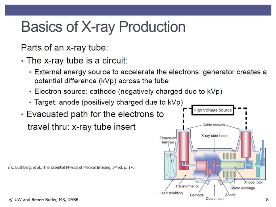
8
Organ Systems Response: Skin
© UW and Kalpana Kanal, PhD, DABR c.f. Bushberg, et al. The Essential Physics of Medical Imaging, 2nd ed., p. 830.

10
Protection Global Perspective TIME
Minimize the amount of time that you spend in the presence of radiation + DISTANCE Increase your physical separation between sources of radiation (Inverse Square Law) + SHIELDING Position yourself such that there is shielding between you and a radiation source ALARA – ‘As low as reasonably achievable’ – this is a guiding principle in radiation protection that takes into account social and economic factors… be reasonable, basically
 + SHIELDING. Position yourself such that there is shielding between you and a radiation source. ALARA – ‘As low as reasonably achievable’ – this is a guiding principle in radiation protection that takes into account social and economic factors… be reasonable, basically.")
11
Global Perspective Radiography X-Ray Tube Patient Detector
Image Receptor: - A) Analog Detector * Screen-film - B) Digital Detector * Computed Radiography * In-direct Digital * Direct Digital X-ray Source: We (or the system) control: - photon energy (kVp) - # of photons produced (mA) - exposure time (sec) X-ray Interactions in Body: - Photo-electric ϵ Z3/E3 - Compton Scatter ϵ 1/E We take advantage of these photon/tissue interactions to create a usable image. • This is classified as transmission imaging (i.e. photons transmit through patient) • This is a 2D PROJECTION of 3D anatomy! - Anatomical overlay (we lack some spatial information) - SOLUTION: Different views (or a different modality) E – photon energy Z – atomic number
 Analog Detector. * Screen-film. - B) Digital Detector. * Computed Radiography. * In-direct Digital. * Direct Digital. X-ray Source: We (or the system) control: - photon energy (kVp) - # of photons produced (mA) - exposure time (sec) X-ray Interactions in Body: - Photo-electric ϵ Z3/E3. - Compton Scatter ϵ 1/E. We take advantage of these photon/tissue interactions to create a usable image. • This is classified as transmission imaging (i.e. photons transmit through patient) • This is a 2D PROJECTION of 3D anatomy! - Anatomical overlay (we lack some spatial information) - SOLUTION: Different views (or a different modality) E – photon energy. Z – atomic number.")
12
BASICS OF RADIOGRAPHY Alright, let’s move on to aim 3, we’ll identify some of the reasons for the volume differences that we observed.

13
Radiography X-ray Tube Trade-offs
This is a summary of the parameters discussed in the module, along with how changing those parameters affects image resolution, field coverage, heat handling, and cost: MAIN IDEA: Geometry matters, pay attention to heat deposition, understand the system config. c.f.: Bushberg, et al, The Essential Physics of Medical Imaging, 3rd Ed, p 181.

14
More energy imparted to e-
Peak KiloVoltage - kVp inc kVp kVp Rules-of-Thumb kVp is related to beam penetrability - higher kVp leads to higher energy x-rays, which can penetrate further into a given medium Modifying the kVp changes the voltage applied between the anode and cathode: Increasing kVp is associated with worsening of low-contrast detectability (see photon interactions as a function of photon energy) Higher Voltage More energy imparted to e- Changing the kVp changes the maximum photon energy that can be created (i.e. most energy transfer to photon is via direct collision of e- with nucleus) – check for moving x-intercept on your spectrum ALL ELSE EQUAL, exposure is proportional to kVp2 We can produce higher energy photons (x-rays), higher yield of characteristic x-rays c.f.: (center) Bushberg, et al, The Essential Physics of Medical Imaging, 2nd Ed, p 98. c.f.: (right) Bushberg, et al, The Essential Physics of Medical Imaging, 3rd Ed, p 203.
 Higher Voltage. More energy imparted to e- Changing the kVp changes the maximum photon energy that can be created (i.e. most energy transfer to photon is via direct collision of e- with nucleus) – check for moving x-intercept on your spectrum. ALL ELSE EQUAL, exposure is proportional to kVp2. We can produce higher energy photons (x-rays), higher yield of characteristic x-rays. c.f.: (center) Bushberg, et al, The Essential Physics of Medical Imaging, 2nd Ed, p 98. c.f.: (right) Bushberg, et al, The Essential Physics of Medical Imaging, 3rd Ed, p 203.")
15
Tube Amperage - mA mA Rules-of-Thumb inc mAs mA is related to number of photons. Higher mA leads to more electrons and more x-rays Modifying the mA changes the current applied to the filament: Increasing mA is associated with the improvement of noise, low-contrast detectability , and better statistics (more counts) in our image Higher current Higher filament temperature This is not a perfect example, but a decrease in mA (for a given exposure time) leads to a loss in x-ray intensity. Notice that the x-intercept is identical at the kVp. More e- boiled off (thermionic emission) ALL ELSE EQUAL, exposure is proportional to mA More photons created c.f.: (center) Bushberg, et al, The Essential Physics of Medical Imaging, 2nd Ed, p 98. c.f.: (right) Bushberg, et al, The Essential Physics of Medical Imaging, 3rd Ed, p 203.
 in our image. Higher current. Higher filament temperature. This is not a perfect example, but a decrease in mA (for a given exposure time) leads to a loss in x-ray intensity. Notice that the x-intercept is identical at the kVp. More e- boiled off (thermionic emission) ALL ELSE EQUAL, exposure. is proportional to mA. More photons created. c.f.: (center) Bushberg, et al, The Essential Physics of Medical Imaging, 2nd Ed, p 98. c.f.: (right) Bushberg, et al, The Essential Physics of Medical Imaging, 3rd Ed, p 203.")
16
Radiography Phototimers
Phototimers (aka Automatic Exposure Control - AEC) are an alternative to manual technique: Measure actual amount of radiation incident on image receptor Signal measured in one of photocells (ion chamber / solid state) Match photocell selection to imaged anatomy Terminates X-ray exposure when proper amount is obtained Radiation Signal in Cell Amplified Comparator for Cutoff (also backup timer) GOAL: provide consistent exposure to image receptor, independent of the particular patient you are imaging FEEDBACK GRID AEC DETECTOR c.f.: Bushberg, et al, The Essential Physics of Medical Imaging, 2nd Ed, p 134.
 are an alternative to manual technique: Measure actual amount of radiation incident on image receptor. Signal measured in one of photocells (ion chamber / solid state) Match photocell selection to imaged anatomy. Terminates X-ray exposure when proper amount is obtained. Radiation Signal in Cell Amplified Comparator for Cutoff (also backup timer) GOAL: provide consistent exposure to image receptor, independent of the particular patient you are imaging. FEEDBACK. GRID. AEC. DETECTOR. c.f.: Bushberg, et al, The Essential Physics of Medical Imaging, 2nd Ed, p 134.")
17
MANUAL EXPOSURE (mA-s)
System Power On/Off Detector Selection Table Bucky Wall Stand* Free Cassette Protocol Selection Focal Spot Size Selection Small Focal Spot (SFS) Medium Focal Spot (MFS) Large Focal Spot (LFS)*
 Medium Focal Spot (MFS) Large Focal Spot (LFS)*")
18
MANUAL EXPOSURE (mAs-s)
Acquisition Mode Manual (mA-s) Manual (mAs-s) AEC
 Manual (mAs-s) AEC.")
19
AEC EXPOSURE Density Steps (Fine Tune) -3 / -2 / -1 / 0 / 1 / 2 / 3*
AEC Sensitivity (Coarse Tune) Chest* CR200 CR300 CR400 Active AEC Photocell Selection (aka - cells, phototimers, chambers) Left Center* Right
 Chest* CR200. CR300. CR400. Active AEC Photocell Selection. (aka - cells, phototimers, chambers) Left. Center* Right.")
20
Techniques Trade-offs
This chart summarizes what the module told us. This is just a first-line representation, DON’T rely on this in all circumstances, a lot depends on other factors that we will keep learning. Notice that for a constant detector exposure, kVp and mAs move in opposite directions. This is why we collectively refer to these parameters as mAs (i.e. product of mA and time), as an indicator of number of photons! Doubling exposure time (s) and halving mA results in: - 1) same number of e- hitting target - 2) same number of x-ray photons - 3) same x-ray spectrum
, as an indicator of number of photons! Doubling exposure time (s) and halving mA results in: - 1) same number of e- hitting target. - 2) same number of x-ray photons. - 3) same x-ray spectrum.")
21
Techniques Trade-offs
Now that we understand mAs, we can further simplify the prior chart. Just remember to account for the potential for patient motion and its relation to exposure time along with tube output limits.

22
Techniques Collimation / Filtration
Filtration – attenuation of x-ray beam as it passes through a layer of material Inherent filtration – via x-ray system components (glass, oil, port, etc…) Added filtration – intentionally added to harden beam (Cu, Al, Rh, Mo) Lowers beam intensity, increases avg beam energy (slight contrast loss), may have to increase technique to get more photons Collimator – used to shape radiation field Blades move in tandem (‘upper set’ pair, ‘lower set’ pair) Recall, smaller radiation field means less scatter, collimate when you can! Smaller exposed area, better for patient dose c.f.: Bushberg, et al, The Essential Physics of Medical Imaging, 2nd Ed, p 115.
 Added filtration – intentionally added to harden beam (Cu, Al, Rh, Mo) Lowers beam intensity, increases avg beam energy (slight contrast loss), may have to increase technique to get more photons. Collimator – used to shape radiation field. Blades move in tandem (‘upper set’ pair, ‘lower set’ pair) Recall, smaller radiation field means less scatter, collimate when you can! Smaller exposed area, better for patient dose. c.f.: Bushberg, et al, The Essential Physics of Medical Imaging, 2nd Ed, p 115.")
23
MAMMOGRAPHY

24
Mammography X-ray Tube Configuration
Cathode side of tube closest to patient (why?) kVp below 40 (high contrast) 1-mm thick Beryllium tube port mA fixed for large and small focal spot phototimers
 kVp below 40 (high contrast) 1-mm thick Beryllium tube port. mA fixed for large and small focal spot. phototimers.")
25
Lower grid ratios used, fiber interspaces
Mammography X-ray Tube Configuration Breast compression is necessary reduces overlapping anatomy and decreases tissue thickness of the breast less scatter, more contrast, less geometric blurring of the anatomic structures, less motion and lower radiation dose to the tissues Lower grid ratios used, fiber interspaces phototimers

26
Mammography X-ray Tube Configuration
Optimal x-ray energy is achieved by use of specific target materials and filters to remove the low- and high-energy x-rays Molybdenum (Mo) and Rhodium (Rh) are used for mammography targets and produce characteristic x-ray peaks at 17.5 and 19.6 keV (Mo) and 20.2 and 22.7 keV (Rh) Added tube filters of the same element as the target reduce the low- and high-energy x-rays in the x-ray spectrum and allow transmission of characteristic x-ray energies Mo/Mo Rh/Rh Mo/Rh W/Rh W/Al
 and Rhodium (Rh) are used for mammography targets and produce characteristic x-ray peaks at 17.5 and 19.6 keV (Mo) and 20.2 and 22.7 keV (Rh) Added tube filters of the same element as the target reduce the low- and high-energy x-rays in the x-ray spectrum and allow transmission of characteristic x-ray energies. Mo/Mo. Rh/Rh. Mo/Rh. W/Rh. W/Al.")
27
Mammography X-ray Tube Configuration

28
Mammography Magnification Magnification of 1.5x to 2.0x
Increased effective resolution Small focal spot size used (lower mA, longer exposure times) Dose increased Reduction of scatter
 Dose increased. Reduction of scatter.")
29
Radiography GRID DETECTOR AEC

30
Mammography AEC MAG STAND GRID DETECTOR DETECTOR AEC GRID
Magnification MAG STAND AEC GRID Breast Tissue DETECTOR SPOT COMPRESSION PADDLE DETECTOR AEC COMPRESSION PADDLE GRID Breast Tissue

31
Questions • Raphex 2000: The decision is made to add 1 mm Al permanently to the filtration of an x-ray beam. This is done in order to reduce the: a) Load on the x-ray tube b) Scatter into the detection system c) Maximum field size d) Overall system latitude e) Patient skin dose Most of the soft (i.e. low energy) radiation in an x-ray beam is absorbed in the patient and does not contribute to the image. Hardening the beam, by adding filtration, reduces the patient’s skin dose for the same radiation reaching the detector.
 Load on the x-ray tube. b) Scatter into the detection system. c) Maximum field size. d) Overall system latitude. e) Patient skin dose. Most of the soft (i.e. low energy) radiation in an x-ray beam is absorbed in the patient and does not contribute to the image. Hardening the beam, by adding filtration, reduces the patient’s skin dose for the same radiation reaching the detector.")
32
Questions • Raphex 2000: Increasing the kVp of an x-ray generator without changing any other control setting will increase the: 1) Amount of heat produced at the anode. 2) Intensity of the x-ray beam. 3) Exposure to a person in the room out of the direct beam. 4) Contrast in a film taken at the higher kVp. 5) Quantum noise in a radiography taken at the higher kVp. a) 1, 3 b) 1, 4 c) 1, 2, 3 d) 2, 3, 4 e) 3, 4, 5 Increasing the kVp increases the kinetic energy of the electrons colliding with the target. This leads to greater x-ray production as well as additional heat load for the target. Contrast is reduced at higher kV settings as is quantum noise, which is inversely related to the number of photons produced.
 Amount of heat produced at the anode. 2) Intensity of the x-ray beam. 3) Exposure to a person in the room out of the direct beam. 4) Contrast in a film taken at the higher kVp. 5) Quantum noise in a radiography taken at the higher kVp. a) 1, 3. b) 1, 4. c) 1, 2, 3. d) 2, 3, 4. e) 3, 4, 5. Increasing the kVp increases the kinetic energy of the electrons colliding with the target. This leads to greater x-ray production as well as additional heat load for the target. Contrast is reduced at higher kV settings as is quantum noise, which is inversely related to the number of photons produced.")
33
Questions • Raphex 2001: The purpose of an x-ray tube filament found in an x-ray circuit is to: a) Allow the current to flow in one direction only b) Increase or decrease voltage c) Create thermionic emission d) Measure the time of the exposure e) Measure tube current The process by which a filament is heated to release electrons is called thermionic emission.
 Allow the current to flow in one direction only. b) Increase or decrease voltage. c) Create thermionic emission. d) Measure the time of the exposure. e) Measure tube current. The process by which a filament is heated to release electrons is called thermionic emission.")
34
Questions • Raphex 2000: To increase the heat handling ability of an x-ray tube while maintaining the same focal spot size, the manufacturer can: a) Decrease the diameter of the rotating anode b) Decrease the rotation speed of the anode c) Decrease the target angle d) Decrease the anode mass e) None of the above A decreased target angle allows a larger physical focal spot for the same effective focal spot size. Decreasing the diameter or rotation speed decreases the kW rating. The anode mass has no influence on the kW rating.
 Decrease the diameter of the rotating anode. b) Decrease the rotation speed of the anode. c) Decrease the target angle. d) Decrease the anode mass. e) None of the above. A decreased target angle allows a larger physical focal spot for the same effective focal spot size. Decreasing the diameter or rotation speed decreases the kW rating. The anode mass has no influence on the kW rating.")
35
Questions • The ratio of heat to x-rays produced in a typical diagnostic target is about: a) 1:99 b) 10:90 c) 50:50 d) 90:10 e) 99:1 Generating x-rays is a highly inefficient process, about 99% of the energy produces heat, which does not help us.
 10:90. c) 50:50. d) 90:10. e) 99:1. Generating x-rays is a highly inefficient process, about 99% of the energy produces heat, which does not help us.")
36
Questions • The effective photon energy of an x-ray beam can be increased by __________: a) Increasing the tube current b) Decreasing the filtration c) Increasing the mAs d) Increasing the tube voltage e) All of the above Decreasing the filtration will increase the intensity, but decrease the effective energy and HVL. Tube current (mA) and mAs have no energy effect.
 Decreasing the filtration. c) Increasing the mAs. d) Increasing the tube voltage. e) All of the above. Decreasing the filtration will increase the intensity, but decrease the effective energy and HVL. Tube current (mA) and mAs have no energy effect.")
37
Questions • In mammography, a fiber interspaced grid is preferred over aluminum because it : a) Reduces the dose b) Improves resolution c) Removes more scatter d) Reduces image mottle e) Improves contrast Aluminum attenuates more of the primary rays than fiber, leading to higher patient doses.
 Improves resolution. c) Removes more scatter. d) Reduces image mottle. e) Improves contrast. Aluminum attenuates more of the primary rays than fiber, leading to higher patient doses.")
38
Questions • What is the effect of magnification on mammography patient dose? 1) increases 2) decreases 3) has no effect Entrance skin exposure and breast dose are reduced because no grid is used, but are increased due to the shorter focus to breast distance.
 has no effect. Entrance skin exposure and breast dose are reduced because no grid is used, but are increased due to the shorter focus to breast distance.")
39
Questions • What change in focal spot and mA occurs when switching from non-magnification mammography to a spot magnification view? a) a smaller focal spot and lower mA b) a larger focal spot and lower mA c) a smaller focal spot and higher mA d) a larger focal spot and higher mA e) no change Magnification uses small focal spot size which improves resolution but has decreased tube heat loading characteristics thus mA is reduced.
 a smaller focal spot and lower mA. b) a larger focal spot and lower mA. c) a smaller focal spot and higher mA. d) a larger focal spot and higher mA. e) no change. Magnification uses small focal spot size which improves resolution but has decreased tube heat loading characteristics thus mA is reduced.")
40
Questions • The tube port (window) for a mammography x-ray tube is typically made of : a) glass b) lead c) tungsten d) beryllium Using beryllium instead of glass reduces attenuation of the low-energy x-rays in mammography
 tungsten. d) beryllium. Using beryllium instead of glass reduces attenuation of the low-energy x-rays in mammography.")
41
Questions • Which part of a mammography x-ray tube is positioned closest to the chest wall of the patient? a) anode end b) cathode end c) side or long axis Continued……
 anode end. b) cathode end. c) side or long axis. Continued……")
42
Questions • The reason the mammography tube is positioned as it is in the previous question is: a) collimation b) half value layer c) heel effect d) penumbra e) technique Due to heel effect - Highest radiation output to thickest part of breast (chest wall) Anode-cathode axis oriented in anterior-posterior direction or Cathode side of tube closest to patient
 half value layer. c) heel effect. d) penumbra. e) technique. Due to heel effect - Highest radiation output to thickest part of breast (chest wall) Anode-cathode axis oriented in anterior-posterior direction or Cathode side of tube closest to patient.")
43
Questions • Compression in mammography results in increased:
a) breast dose b) geometric blurring c) patient motion d) scatter e) none of the above Patient motion, blurring, scatter and dose all reduce due to compression of breast.
 breast dose. b) geometric blurring. c) patient motion. d) scatter. e) none of the above. Patient motion, blurring, scatter and dose all reduce due to compression of breast.")
44
Questions • The low voltage used in screen/film mammography reduces :
a) Subject contrast b) Dose c) Microcalcification visibility d) Scatter e) Film processing time Low kV needed to optimize contrast, photoelectric interaction, not Compton interaction.
 Subject contrast. b) Dose. c) Microcalcification visibility. d) Scatter. e) Film processing time. Low kV needed to optimize contrast, photoelectric interaction, not Compton interaction.")
Similar presentations