Download presentation
Presentation is loading. Please wait.

1
Forming and shaping plastics and composite materials
Group 1 November 2, 2005 Bradley Wood Wayne Yevoli Andri Ulrich

2
Plastic molding Truck delivers plastic resin pellets. This is then blown into the Storage silo. There may be as many as a dozen types of resin pellets all stored in separate silos.

3
Plastic molding Silo’s feed the resin pellets into individual machines located within the factory

4
Tube extrusion process
The body of the tube is extruded. This involves feeding the resin pellets in an extruder which is heated to melt and plasticize the resin.

5
Tube extrusion process
A rotating screw (auger) forces the plastic along to the end where the molten plastic passes through a die to produce a continuous tube of the desired size and shape. The extruder screw works in a continuous motion, turning faster to pump more plastic through as required, and meaning that the control of rotation speed control is critical.
 forces the plastic along to the end where the molten plastic passes through a die to produce a continuous tube of the desired size and shape. The extruder screw works in a continuous motion, turning faster to pump more plastic through as required, and meaning that the control of rotation speed control is critical.")
6
Tube extrusion process
Following extrusion, the molten tube is cooled with water then cut to the desired length, to form individual tubes.

7
Tube extrusion process
This is then painted using a rotary dry offset printing process (up to 5 colors) A varnish or lacquer is then applied to the tube to provide a durable, smooth glossy high quality feel and appearance
 A varnish or lacquer is then applied to the tube to provide a durable, smooth glossy high quality feel and appearance.")
8
Tube extrusion process
The second stage involved injection molding the head of the tube, either separately or directly onto the tube. If made separately the head can be welded onto the tube in a separate operation.

9
Tube extrusion process
Caps and closures are manufactured through an injection molding process, described below. The caps and closures are placed on the tubes, before they are boxed ready to shipping.

10
Tube extrusion process
Production customers fill the tubes from the other end, then seal the base of the tube ready for use.

11
Tube extrusion process
This is a Single Screw Extruder Line for making Pipe & Profile of PVC or PE or PP

12
Tube extrusion process

13
Tube extrusion process

14
Tube extrusion process

15
Extrusion blow molding
Resin pellets can be blended with colors and other additives and fed through a heated extruder to blend and plasticized.

16
Extrusion blow molding
The hot molten plastic is extruded through a purpose shaped head into a short tube called a “parison”. A parison program controls the wall thickness of the parison when passing through the extruder head.

17
Extrusion blow molding
While the parison is still hot and molten, the mold which is in two halves closes around, trapping the parison inside the mold. The parison is cut off by a hot knife at the top and the closing mold also pinches and seals at the bottom.

18
Extrusion blow molding
The blow pin passes into the still open end of the parison, squeezing the plastic to the shape of the neck opening and then blows the parison with about 400 to 800 kPa of air. This air pressure blows the parison out to take shape of the bottle mold.

19
Extrusion blow molding
After the completed cooling cycle the mould opens and releases the product. At the same time a small excess of now cool and hard plastic at the neck and bottom called “flashes” are removed. These small amounts of flashing can be recycled directly back into the process.

20
Extrusion blow molding

21
Extrusion blow molding

22
Extrusion blow molding
Molded products are tested and inspected for defects

23
Extrusion blow molding

24
Extrusion blow molding

25
Injection molding Blended Resin is then fed through a heated extruder to blend and plasticize. The injection molding machine is equipped with a reciprocating screw (usually driven by a hydraulic motor).
.")
26
Injection molding This type of screw can rotate to pump plastic forward and also move forward and back. Moving forward forces the molten polymer into a temperature controlled split mold via a channel system of gates and runners.

27
Injection molding The pressure of injection is high, to force the molten polymer into every gap in the closed mould in less than a few seconds. Dependant on the material being processed; injection pressure can be up to one thousand atmospheres.

28
Injection molding Screw rotates back to recharge the barrel with another shot of plastic. Mold coolant cools and solidifies the plastic.

29
Injection molding As the Mold opens ready for ejection of component an ejector bar strikes a stop and activates a mechanism to push the now solid part from the mould.

30
Injection molding After the components drops out of mold, the mold closes and is ready to be refilled in another cycle. Depending on part size, complete cycle times can vary form just a few seconds to about 1 minute.

31
Injection molding

32
Injection molding Parts tested and inspected for defects.

33
Injection molding

34
Injection molding Toshiba machine showing the injection molding process Capable of 1450 tons to 3850 tons compression

35
Injection molding

36
References http://www.toshiba-machine.com/

37
Rapid Prototyping Forming/Shaping Plastics and Composites

38
Forming/Shaping Plastics and Composites
Transfer Molding Casting Foam Molding Cold Forming Processing Polymer-Matrix Composites Processing Metal-Matrix Composites Design Considerations

39
Transfer Molding: Similar to compression molding
Used for complex parts and parts having varying wall thicknesses Uncured thermosetting resin is heated Resin is injected into heated molds (closed) under high pressure Resin cures by cross-linking
 under high pressure. Resin cures by cross-linking.")
40
Transfer Molding: Used to make: electrical connectors, electronic components, encapsulation of microelectronic devices

41
Casting: Open Mold and Centrifugal
Same process as casting metal Can be used with thermosetting plastics, nylon and acrylics In open molds, liquid plastic is poured into open molds In centrifugal casting, the mold is spun to force the liquid plastic into mold

42
Casting: Open Mold and Centrifugal

43
Casting: Potting and Encapsulation
Casting plastic around electrical components Used to coat transformers, transistors, etc. Plastic can serve as a non-conductor

44
Casting: Potting and Encapsulation

45
Foam Molding Polystyrene beads are placed in a mold and heated
Beads will expand up to 50 times their original size Changing the bead size will determine the density of the finished foam part Used to make styrofoam cups, insulating blocks and packaging materials

46
Foam Molding

47
Cold Forming/Solid-Phase Forming
Similar forming process as with metals: rolling, closed-die forging, coining, deep drawing Limited to polymers that are sufficiently ductile at room temperatures Increases strength and toughness Faster production

48
Cold Forming/Solid Phase Forming

49
Processing Polymer-Matrix Composites
PMCs have high strength/stiffness to weight ratio and excellent creep resistance. They consist of the polymer and reinforcing fibers, bonded together in various ways.

50
Polymer-Matrix Composites: Fiber Impregnation
Fibers can consist of fiberglass, graphite, boron, ceramic and kevlar. Prepregs are made by dipping continuous fibers in resin.

51
Polymer-Matrix Composites: Fiber Impregnation
Sheet-molding compounds are made by dropping randomly oriented pieces of fiber on a layer of resin paste, under which there is a thin sheet of polymer (carrier film).
.")
52
Polymer-Matrix Composites: Molding of Reinforced Plastics
In compression molding, a mixture of semi-liquid polymers, fibers and additives is placed between two molds, and pressure is applied. In vacuum-bag molding, prepregs are formed into the shape of the mold using vacuum pressure. Pressure-bag molding is like vacuum-bag molding, except air pressure is applied to form the prepregs into the desired shape.

53
Polymer-Matrix Composites: Molding of Reinforced Plastics

54
Polymer-Matrix Composites: Molding of Reinforced Plastics
In contact molding, fibers are impregnated in an open mold, either by hand using a brush or by a spray machine.

55
Polymer-Matrix Composites: Examples

56
Polymer-Matrix Composites: Filament Winding
Fibers are dipped in resin bath They are then wrapped around an object by means of rotating mandrel Used to strengthen pressure vessels.

57
Polymer-Matrix Composites: Filament Winding

58
Polymer-Matrix Composites: Pultrusion
Fibers are run continuously through a resin bath before being pulled through a set of dies. Used to make golf clubs, ski poles, ladders.

59
Polymer-Matrix Composites: Pultrusion

60
Polymer-Matrix Composites: Pulforming
Fibers are passed through a resin bath, and are then clamped in a fixed die to cure. Used to make archery bows, industrial springs, and suspension components for cars.

61
Polymer-Matrix Composites: More Examples

62
Metal-Matrix Composites: Liquid Phase Processing
Liquid metal-matrix and solid reinforcement are either cast or pressure-infiltration cast Metal-matrix is usually aluminum or titanium Solid reinforcement is usually graphite, aluminum oxide or silicon carbide.

63
Metal-Matrix Composites: Solid Phase Processing
Powder-metallurgy techniques are used Example: tungsten-carbide reinforced tools.

64
Design Considerations: Plastics and Composites
Compared to metals, plastics have lower stiffness and strength. Dimensional tolerances, except with injection molding, are higher than with metals For casting, ensuring proper flow into mold cavities is important Variations in section thicknesses or abrupt changes in geometry should be avoided.

65
Design Considerations: Plastics and Composites

66
Design Considerations: Plastics and Composites
Proper draft angles need to be established to ensure release from molds Shrinkage must be taken into account Residual stresses can be present in plastics and composites depending on their processing method Fiber direction in reinforced plastics

67
Rapid-Prototyping Operations

68
What is RP Prototype - an original type, form, or instance serving as a basis or standard for later stages.

69
Advantages of RP Physical models produced from CAD data files
Prototype can be used in subsequent manufacturing operations RP operations used to produce actual tooling for manufacturing

70
RP processes can be classified into three major groups:
Subtractive – material removed from workpiece Additive – part is built up by adding material incrementally Virtual – advanced computer-based visualization technology is used

71
Subtractive Processes
Processes using a variety of tooling and machines Takes from a few days to a few weeks to create a prototype

72
To speed up the process, computer-based technologies are used such as:
Computer-based drafting packages (CAD) Interpretation software Manufacturing software Computer-numerical-control machinery
 Interpretation software. Manufacturing software. Computer-numerical-control machinery.")
73
Computer-based drafting packages (CAD)
")
74
Interpretation Software
Translates the CAD file into a format usable by manufacturing software.

75
Manufacturing Software
Capable of planning the operations required to produce the desired shape

76
Computer-numerical-control Machinery

77
Parts are built up layer-by-layer
Additive Processes Parts are built up layer-by-layer Operations consist of: Stereolithography Fused-deposition modeling Ballistic-particle manufacturing and 3-D printing Selective laser sintering

78
Steps Obtain CAD file description of the part
Computer constructs slices of the 3-D part Each slice is analyzed separately Set of instructions is compiled providing the machine with detailed information on how to build the part Part is manually finished

79
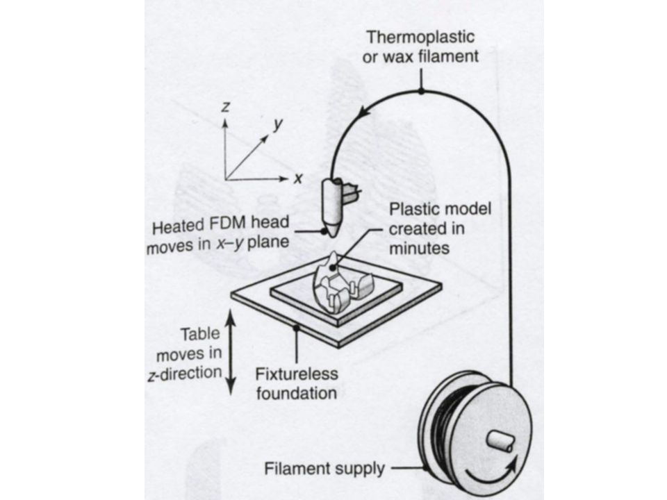
Fused-deposition modeling (FDM)
Gantry-robot controlled extruder head moves over a table Table can be raised or lowered as needed A thermoplastic or wax filament is extruded through the small orifice of a heated die Initial layer placed on a foam foundation Table is lowered for each layer until part is finished

81
Supports needed

82
Stereolithography (SLA)
A liquid photopolymer is cured into a specific shape A vat filled with a photocurable liquid-acrylate polymer (mixture of acrylic monomer, oligomers (polymer intermediates), and a photoinitiator) A table is lowered slightly into the liquid and a laser generated UV beam is focused on it, producing a solid body Table is lowered and next layer is cured
, and a photoinitiator) A table is lowered slightly into the liquid and a laser generated UV beam is focused on it, producing a solid body. Table is lowered and next layer is cured.")
84
Part is then Cleaned ultrasonically and in an alcohol bath
Removed from support structure Placed in an oven for final curing processes

85
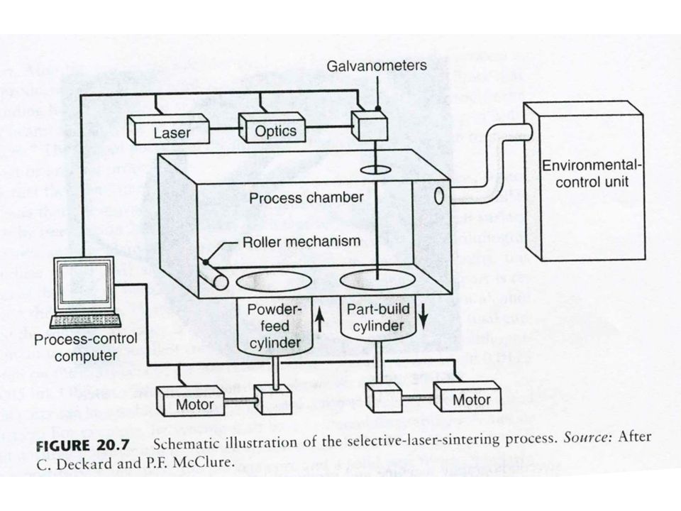
Selective Laser Sintering (SLS)
A powder (usually nonmetallic) is sintered selectively by a laser Powder that is not sintered supports the part so additional supports are not needed
 is sintered selectively by a laser. Powder that is not sintered supports the part so additional supports are not needed.")
87
Materials used in SLS Polymers such as: ABS PVC Nylon Polyester
Polystyrene Epoxy Other materials such as: Wax Metals Ceramics

88
Ballistic-particle Manufacturing
A stream of material (plastic, ceramic, metal, or wax) is ejected through a small orifice at a surface using an ink-jet type mechanism Mechanism uses a piezoelectic pump, which generates a shock wave that propels 50-μm droplets at a rate of 10,000/sec
 is ejected through a small orifice at a surface using an ink-jet type mechanism. Mechanism uses a piezoelectic pump, which generates a shock wave that propels 50-μm droplets at a rate of 10,000/sec.")
89
Three-dimensional Printing (3DP)
Same as Ballistic-particle manufacturing with exception that the print head deposits an inorganic-binder onto a layer of ceramic or metal powders instead of the actual prototype material. Can be combined with sintering to produce fully dense parts

90
Using RP operations to create tooling for creating a part
Rapid Tooling (RT) Using RP operations to create tooling for creating a part
 Using RP operations to create tooling for creating a part.")
92
References

93
References http://www.pullmanmfg.com/value.html
94
References US:official_s%26sa%3DN

Similar presentations


>")

>")


