Download presentation
Presentation is loading. Please wait.

1
TURBINES

2
HYDROELECTRIC POWER PLANT

3
A turbine is a rotary engine that extracts energy from a fluid flow and converts it into useful work
Eg: steam turbine, gas turbine, hydraulic turbine Hydraulic Turbines transfer the kinetic energy and potential energy of water into a rotation . We can generate electricity by coupling to electric generator

4
Axial Flow Radial Flow Tangential Flow Mixed Flow
CLASSIFICATION OF HYDRAULIC TURBINES: 1. BASED ON FLOW PATH Axial Flow Radial Flow Tangential Flow Mixed Flow

5
Classification of Hydraulic Turbines: Based on flow path
Axial Flow Hydraulic Turbines: flow path of the liquid mainly parallel to the axis of rotation. Eg: Kaplan turbine Radial Flow Hydraulic Turbines: liquid flowing mainly in a plane perpendicular to the axis of rotation. Tangential Flow Hydraulic Turbines: liquid flowing mainly in a plane tangential to the turbine. Eg: Pelton turbine

6
Classification of Hydraulic Turbines: Based on flow path Mixed Flow Hydraulic Turbines: For most of the Hydraulic Turbines used there is a significant component of both axial and radial flows. They are called as Mixed Flow Turbines. Francis Turbine is an example of mixed flow type, in Francis Turbine water enters in radial direction and exits in axial direction.

7
CLASSIFICATION OF HYDRAULIC TURBINES
BASED ON WORKING PRINCIPLE Impulse turbine Reaction turbine

8
Classification of Hydraulic Turbines: working principle
Impulse Turbine: The pressure of liquid does not change while flowing through the rotor of the machine. Pressure change occur only in the nozzles of the machine. Eg : Pelton Turbine. The energy to rotate an impulse turbine is derived from the kinetic energy of the fluid flowing through the nozzles.

9
Classification of Hydraulic Turbines: working principle
Reaction Turbine: The pressure of liquid changes while it flows through the rotor of the machine. The change in fluid velocity and reduction in its pressure causes a reaction on the turbine blades. Eg: Francis and Kaplan Turbines

10
Impulse turbine

11
PELTON TURBINE POWER PLANT

12
PELTON TURBINE

13
Parts of pelton turbine
Nozzle with flow regulating arrangement Runner with split buckets Casing Braking nozzle

14
Working Principle

15
The Basic Working Principle
When a high speed water jet injected through a nozzle hits buckets of Pelton wheel; it induces an impulsive force. This force makes the turbine rotate. The rotating shaft runs a generator and produces electricity. Pelton turbine transforms kinetic energy of water jet to rotational energy

16
Governing in Pelton Wheel

17
REACTION TURBINE

18
Francis Turbine

19
Francis Turbine: Penstock: It is a large size pipe which conveys water from the upstream to the dam/reservoir to the turbine runner. Spiral Casing: It constitutes a closed passage whose cross-sectional area gradually decreases along the flow direction; area is maximum at inlet and nearly zero at exit. Guide Vanes: These vanes direct the water on to the runner at an angle appropriate to the design, the motion of them is given by means of hand wheel or by a governor.

20
Governing Mechanism: It changes the position of the guide blades/vanes to affect a variation in water flow rate, when the load conditions on the turbine change. Runner and Runner Blades: The driving force on the runner is both due to impulse and reaction effect Draft Tube: It is gradually expanding tube which discharges water, passing through the runner to the tail race.

21
WORKING Francis turbine operates under medium heads.
Water is brought down to the turbine through a penstock and directed to a number of stationary blades fixed all around the circumference of the runner. These stationary blades are called as guide vanes. Water under pressure, enters the runner from the guide vanes towards the center in radial direction and discharges out of the runner axially.

22
Due to the difference of pressure between guide vanes and the runner (called reaction pressure), the motion of runner occurs. As the water flows through the runner its pressure and angular momentum reduces, This will produce a reaction force on the runner blades. The pressure at inlet is more than that at outlet. The moment of runner is affected by the change of both the potential and kinetic energies of water. After doing the work the water is discharged to the tail race through a closed tube called draft tube

23
Kaplan Turbine:

26
It is a axial flow reaction turbine
Kaplan turbine water flows parallel to the axis of rotation of the shaft. It is a axial flow reaction turbine It is suitable when large quantity of water at low head is available. Main parts are Guide vanes Hub with vanes or runner of the turbine Draft tube

27
For kaplan turbine shaft of the turbine is vertical
Lower end of the shaft is made larger called HUB or BOSS The vanes are fixed on the hub & hence it acts as a runner. The vanes of the hub are adjustable for kaplan turbine

28
Impulsive force is rotating the turbine
SL NO IMPULSE TURBINE REACTION TURBINE 1 Impulsive force is rotating the turbine Reaction force is rotating turbine 2 Pressure of liquid is decreasing in nozzle before entering to turbine Pressure decreases as it flows over the blades 3 Blades are of symmetrical profile Blades having aerofoil profile 4 The size of turbine is small for the same power output Size of reaction turbine is large for the same power output 5 Whole pressure energy of water is converted into kinetic energy before passed onto turbine wheel Part of pressure energy only converted to kinetic energy 6 Water discharges directly from turbine wheel to tail race Water discharges into a draft tube then it is finally discharged to tail race 7 Pressure of water will be atmospheric as it flows over moving blades Pressure of water continuously decreases as it flows over the blades

29
PUMPS

30
HYDRAULIC PUMPS A pump is a device used to transfer fluids from lower elevation to higher elevation. The hydraulic machines which convert the mechanical energy into hydraulic energy are called pumps. The hydraulic energy is in the form of pressure energy. This pressure energy is converted into potential energy, as the liquid is lifted from a lower level to a higher level.

31
Uses of Pumps Used for irrigation purposes and in chemical industries, petroleum industries, etc. Used to feed the water into the boiler (called Feed Water Pump) in power plants. Used to circulate water in the condenser (called Condensate Pump) Used to remove the condensed steam from the condenser (called Condensate extraction Pump) Used to transfer the oil from the reservoir to its proper place in I.C. Engines. Used to force the lubricating oil into the moving or rotating parts of I.C. Engines.
 in power plants. Used to circulate water in the condenser. (called Condensate Pump) Used to remove the condensed steam from the condenser (called Condensate extraction Pump) Used to transfer the oil from the reservoir to its proper place in I.C. Engines. Used to force the lubricating oil into the moving or rotating parts of I.C. Engines.")
32
CLASSIFICATION OF PUMPS
Pumps are broadly classified into Positive- displacement pumps Rotodynamic pumps Positive- displacement pumps: They make a fluid move by trapping a fixed amount and displacing the trapped volume into the discharge pipe. Discharge is directly proportional to speed. Eg : Reciprocating pump, Vane pump, Gear pump

33
Rotodynamic pumps: It is a machine in which energy is continuously imparted to the pumped fluid by means of a rotor and thus fluid is raised to higher elevation. Eg: Centrifugal pump

34
RECIPROCATING PUMP

35
During the motion of piston from left to right a partial vacuum created inside the cylinder.
Because of this low pressure water will rise from well through suction tube and fill the cylinder by forcing to open the suction valve. This operation is known as suction stroke.(motion of piston from left to right). In this stroke crank rotates θ=0˚ to θ=180˚. Also delivery valve will be closed and suction valve will be open during this stroke.
. In this stroke crank rotates θ=0˚ to θ=180˚. Also delivery valve will be closed and suction valve will be open during this stroke.")
36
When the crank rotates from θ=180˚ to θ=360˚ piston moves inwardly from position right to left.
Now piston exerts pressure on the liquid and due to which suction valve closes and delivery valve opens. The liquid is then forced up through delivery pipe. This stroke is known as delivery stroke. Now the pump has completed one cycle. The same cycle repeated as the crank rotates.

37
Crank is rotated by means of an electric motor
Movement of piston is obtained by connecting it to the crank by using a connecting rod Suction and delivery valves are one way or non return valve

38
Discharge through a reciprocating pump

40
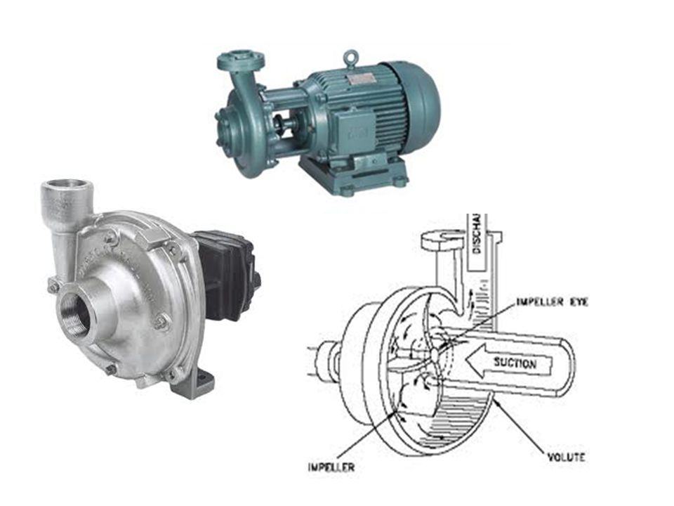
Centrifugal pumps A centrifugal pump is a rotodynamic pump that converts mechanical energy to hydraulic pressure energy. It uses a rotating impeller to increase the pressure of a fluid. The fluid enters the pump impeller along or near to the rotating axis and is accelerated by the impeller, flowing radially outward

44
COMPONENTS Impeller- it is a wheel or rotor which is provided with a series of backward curved blades or vanes. It is mounted on a shaft which is coupled to an electric motor. Volute casing- it is an air tight chamber which surrounds the impeller. Suction pipe- it is a pipe which connected to the inlet of pump. The other end is dips into water in a sump or well. Foot valve and strainer are connected to it.

45
Delivery pipe- it is a pipe which connected to the outlet of pump and it delivers the water into the required height. Delivery valve- controls the flow from pump to delivery pipe

46
WORKING The first step is priming.
Priming is the process of filling the water in suction pipe, casing and portion of delivery pipe up to delivery valve. So that all air from this portion is driven out Pressure generated in a pump impeller is directly proportional to the density of fluid that is in contact with impeller. So if air is there, only negligible pressure would produced with the result that no liquid will be lifted up.

47
After the pump is primed, electric motor started to rotate the impeller.
Due to rotation impeller rotation, produces a vortex which imparts a centrifugal head to liquid. Then the liquid starts to flow in an outward radial direction thereby leaving the vanes of impeller. At the centre of impeller a partial vacuum is created , causes the liquid from sump or well to rush through suction pipe to the eye of impeller.

49
THANK YOU

Similar presentations